Electronics production
Characterize the design rules for your PCB production process:document feeds, speeds, plunge rate, depth of cut (traces and outline) and tooling.
Document your work (in a group or individually).
Individual assignment:
Make an in-circuit programmer by milling and stuffing the PCB, test it, then optionally try other PCB fabrication process.
Learning outcome:
Described the process of milling, stuffing, de-bugging and programming.
Demonstrate correct workflows and identify areas for improvement if required.
This week Eng. Yousef AlSenwar explained for us more about this assignment, he showed us how to use the Carvy milling machine, how to solder and how to find the cracks in our circuits.
For the indivual assigment I will make an in-circuit programmer by milling and stuffing the PCB, then test it. I will follow the models presented by Prof.Neil. I choose the basic FabTinyStar.IPS because it is prepared to connect directly to the USB port of the computer, The FabTinyStar It is another version of an AVR ISP programmer/board that can be produced in a fablab using a milled PCB and readily available components. I downloaded the .png files of the board from the general FabAcademy Week 04 assignment page. There are two files, the traces image defines the lines and connections and the interior are the borders to cut the final board.
PCB Fabrication
After I read the tutorial and watched the lecture by Prof.Neil, I got so excited after he said "we would learn how to make an in-circuit programmer it suppose to program author circuits, the presses will coast less than one dollar."
All we need for the first step are milling machine, a piece of copper-clad laminate PCB and Finlay CAD design, and some electronice components.
Preparing the design for milling by Easel
To control the cutting and set the setting useing Easel Easel it is an online software from Carvey.
1. I saved the design by using Inkscape and save it as .Png and .svg too. I imporedt the design as .Png


- 2. I chose the material and add the dimensions, and thickness.
- For engraving Milling bit 1/64in.
- For cutting Up cut 1/32in.
- Soldering Iron.
- Wire Cutter.
- Soldering Tools For Desoldering.
- Solder wick.
- Tweezers.
- Wet Sponge.
- Soldering Stand.
- Safety Glasses.
- multimeter.
- GNU AVR toolchain
- Building the FabTinyISP
After downloaded,I installed four main programs : - Git
- Atmel GNU Toolchain
- GNU Make
- Avrdude
Ensure to add the path to your System Enviroment after insstalled all the programs by going to Control Panel >> System >> Advanced System Settings >> Enviroment Variables and add to the PATH variable the folder where you have avrdude.exe.


Next step is building a firmware by downloading the file from the assignment webpag
I used Arduino to upload an built in xample >> ArduinoISP.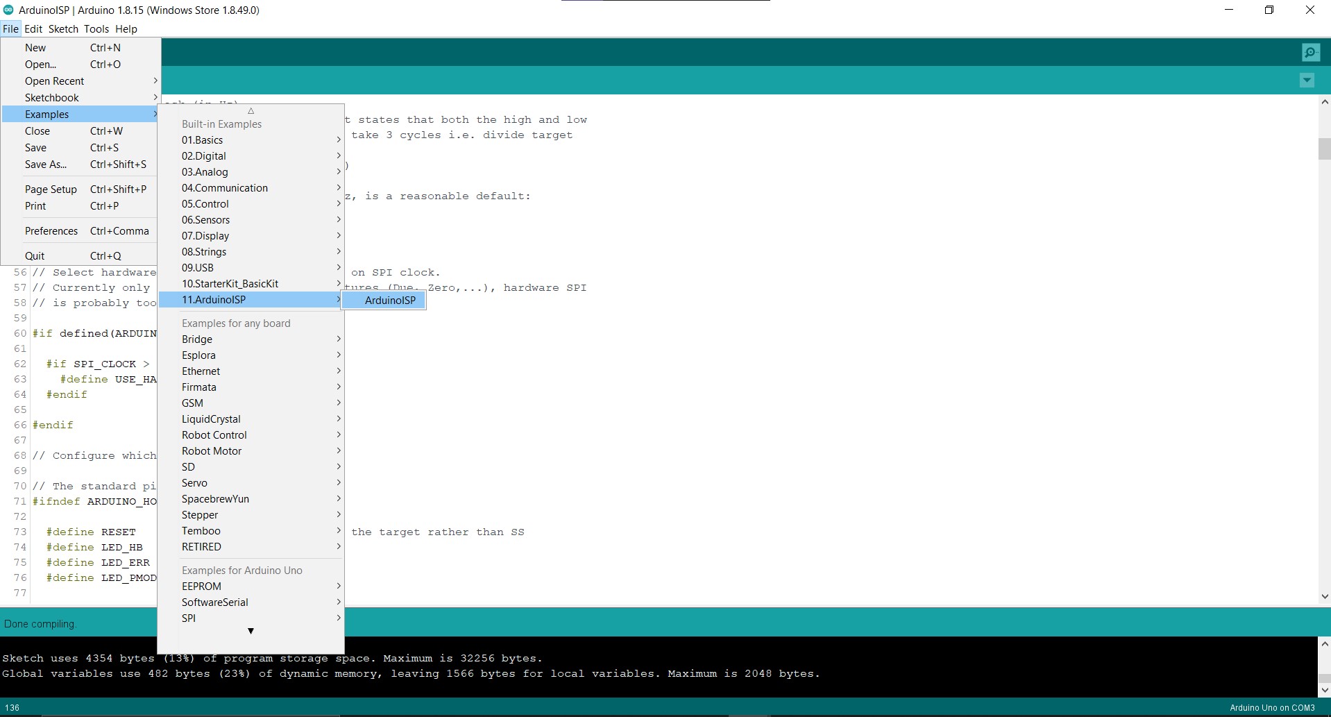
After uploaded the sketch successfully, I connected the Arduino with my board with 6 pins.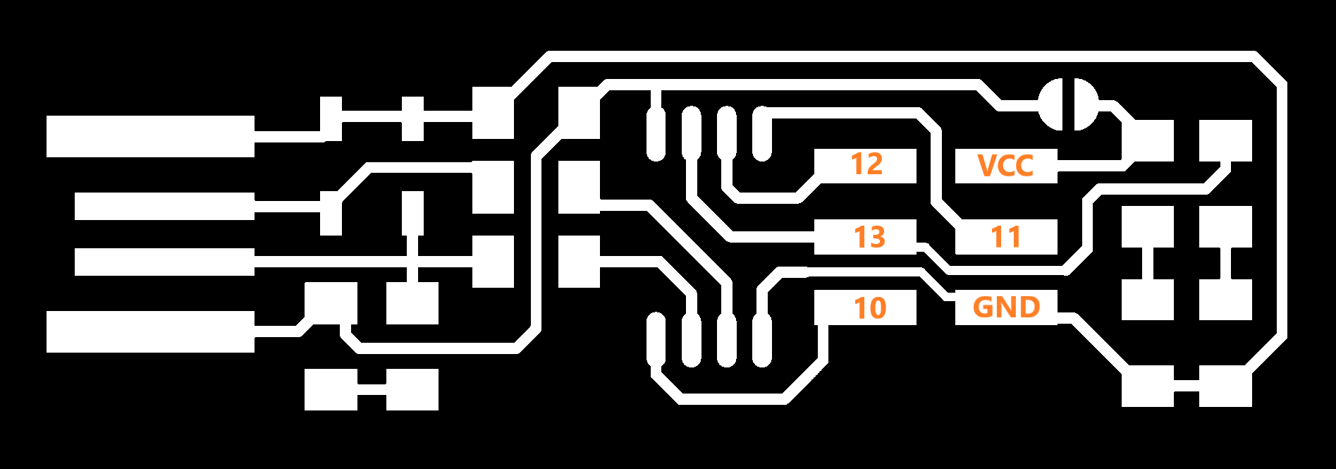
Each pin refer to an Arduino pin.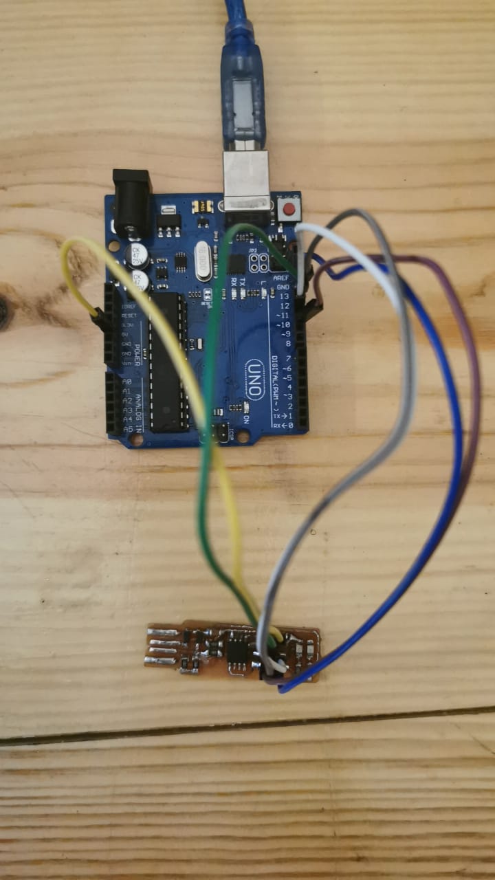
All are connected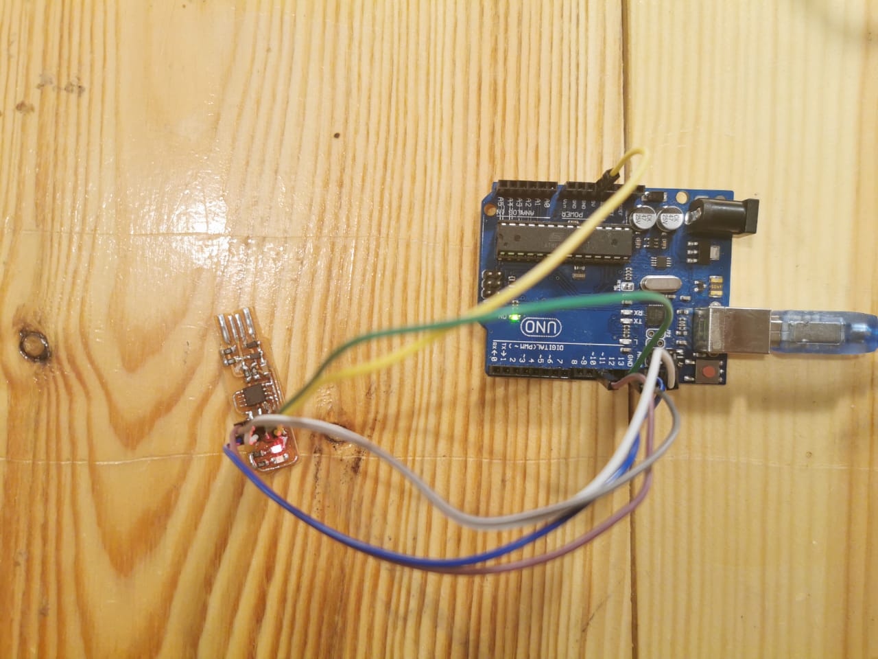
Now the LED light on!
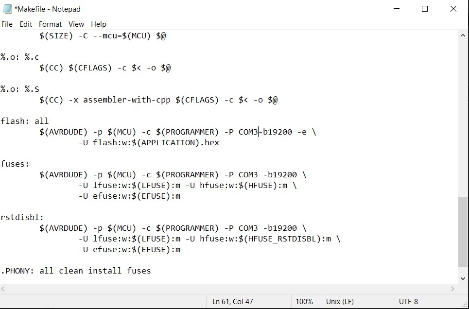
After unzibed the folder I edited the "makefile" using Notepad by changing the COM10 to COM3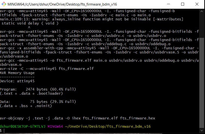
By opening the firmware with choosing Git bash here Open a terminal and navigate to the firmware folder. Use the next sequence of commands: - 'make clean'removes all autogenerated files
- 'make' to builds the .hex file
- 'make flash' uses the programmer to load it onto the target chip.
- 'make fuses' programs the fuse bits on the target chip.
- 'make rstdisbl' blows the reset fuse.
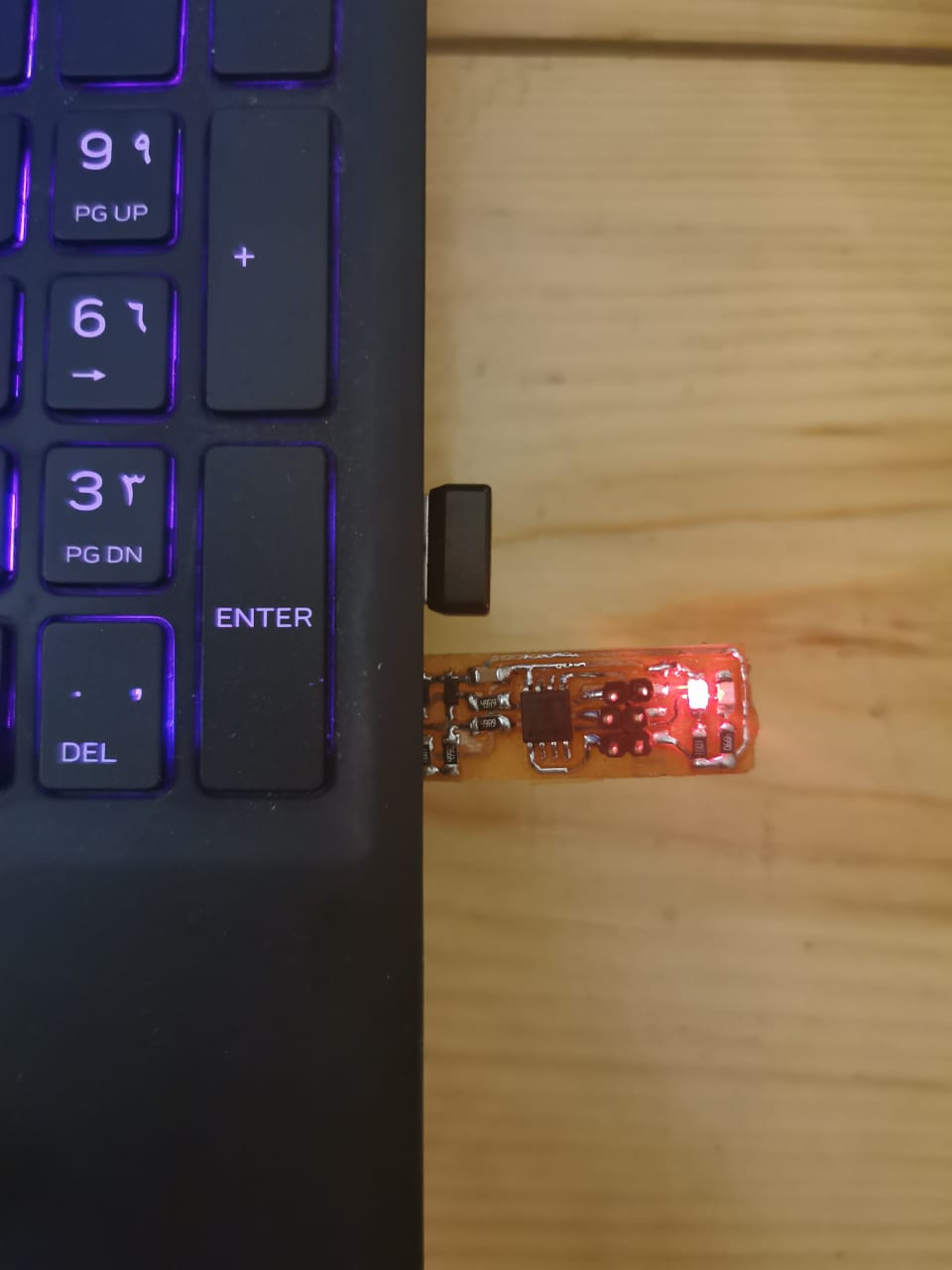
Flashing!
Group assigment
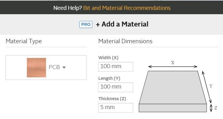
3. I added the bit size.
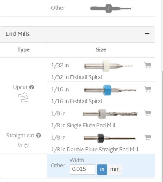
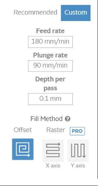
4. I set the setting for engraving.
Milling process
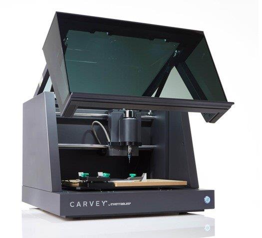
I used Carvey machine.I pluged in the machine and connected to my laptop throw the website, to send the cutting order to the Carvey machine.
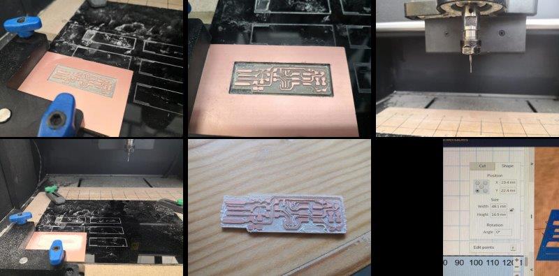
I prepared my piece by adding a double-sided tape from the back. I tried to change the bits.Then I started the cutting.
Prepare Soldering Tools

First Trail
Electronics Components:
1x ATtiny45 or ATtiny85
2x 1kΩ resistors
2x 499Ω resistors
2x 49Ω resistors
2x 3.3v Zener diodes
1x red LED
1x green LED
1x 100nF capacitor
1x 2x3 pin header
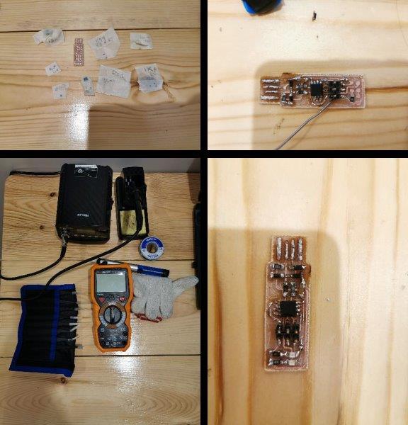
It was my First trail for soldering electronics tiny parts, It was a challenge, but in the same time, I learned more about how to solder and make sure all the paths are connected as in the circuit diagram, my first trail was not succeed, because by mistake I soldered in high temperature and some parts got burn, I was using uncontrolled temperature soldering iron. Also I forgot to solder the ATtiny45 in the right position.
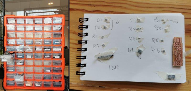
It is my second trail for soldering electronics tiny parts. This time, I collect again all the Components In my notebook and name it as written in the stigmatic drawing. I prepare the multimeter to check all the paths and make sure of the connection, I borrowed one controlled temperature solder iron, and started soldering.
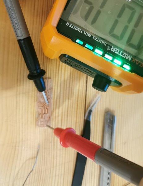
While checking the pcb connection.
- Start with the most difficult parts (the ATtiny45) first, so you have the most access.
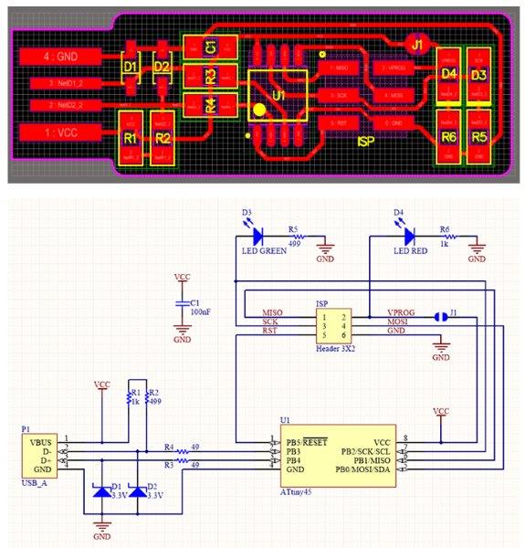
I follow the schematic drawing while soldering after check the traces.
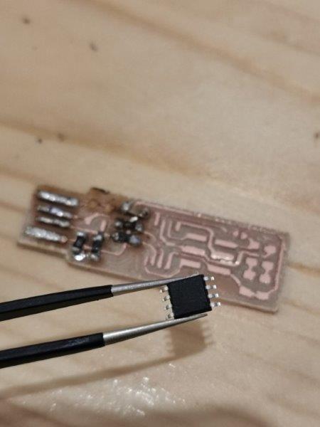
I soldered the microcontroller first
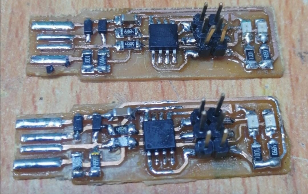
I did more copies since the previous ones does not work.
programming and testing
In this stage, I follow these two tutorials to understand moree: