Interface And Application Programming
Group assignment:
Compare as many tool options as possible.
Individual assignment:
Write an application that interfaces a user with an input and/or output device that you made.
Learning outcomes:
Interpret and implement design and programming protocols to create a Graphic User Interface (GUI).

what is an API? (Application Programming Interface)
API is the acronym for Application Programming Interface, which is a software intermediary that allows two applications to talk to each other.
Each time you use an app like Facebook, send an instant message, or check the weather on your phone, you’re using an API.
What Is an Example of an API?
imagine you’re sitting at a table in a restaurant with a menu of choices to order from. The kitchen is the part of the “system” that will prepare your order.
What is missing is the critical link to communicate your order to the kitchen and deliver your food back to your table.
That’s where the waiter or API comes in. The waiter is the messenger – or API – that takes your request or order and tells the kitchen – the system – what to do.
Then the waiter delivers the response back to you; in this case, it is the food.
Composite user interfaces (CUI) are UIs that interact with two or more senses.
The most common CUI is a graphical user interface (GUI), which is composed of a tactile UI and a visual UI capable of displaying graphics.
A GUI (graphical user interface) is a system of interactive visual components for computer software. GUI objects include icons, cursors, and buttons.
These graphical elements are sometimes enhanced with sounds, or visual effects like transparency and drop shadows.
When sound is added to a GUI it becomes a multimedia user interface (MUI).
The user interface or human–machine interface is the part of the machine that handles the human–machine interaction.
Membrane switches, rubber keypads and touchscreens are examples of the physical part of the Human Machine Interface which we can see and touch.
Individual assignment.
In this assignment we supose to write an application that interfaces a user with an input and/or output device that I made. So I decided to try some games and controlling some outputs. After I read about GUI, I searched for tools I can use it with this assignment. Our mentor Eng. Yousef Alsenwar suggested to us in our last virtual meeting to use Processing and LabView. First, I started searching for applications by using UI, I used before scratch it was pretty much similar to some applications I saw. Then I searched about how to connecting Arduino to smartphone Apps this will be very useful tool. I found many tutorials using Arduino with smartphone. While I was searching, I found a program scratch based form STEMpedia it called Pictoblox, I will try to do sothing with the program.
Check this link for more programs: Interfacing Arduino with software
PictoBlox
PictoBlox is a visual programming environment, you can create programs without needing to type in any code. The code you create is represented by blocks that each have pre-determined values. By combining certain groups of blocks together, they can create programs that tell a robot specific actions to take and moves to make. It is Free and there are many features, one of the feature I really like it, it’s connected with Dabble App it allow you to transform your smartphone into a virtual I/O device to easily make various DIY projects and IoT applications.
Dabbleit is a tool for easily programmable with both Scratch and Arduino thus making it suitable for everyone. Also it provides you with a lots of modules to control hardware via Bluetooth , communicate with it, access sensors like accelerometer, GPS, proximity and others.
To download both programs: PictoBlox Dabble
Testing PictoBlox
I’ll try to control first the build in LED in the Arduino, then I will control external LED by Bluetooth. I download the program PictoBlox.
Components needed :
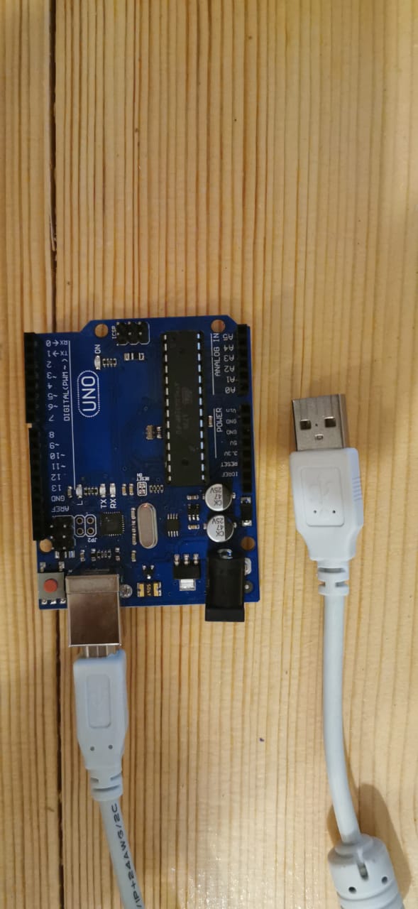
Connctions and coding:
1.Plug in the Arduino via usb cable.

2.Go to Bored button in the toolbar then select your Arduino, I chose Arduino Uno.

3.Conncte the bored to the port, for me it was com6.

4.Set the code from the Code palette as shows below.
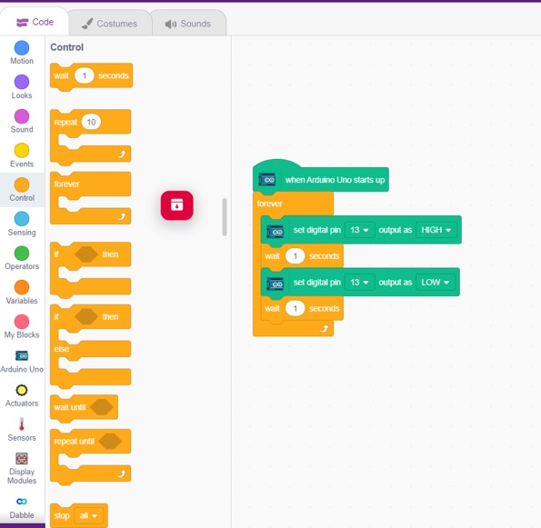
5.Go to Stage then upload the code.
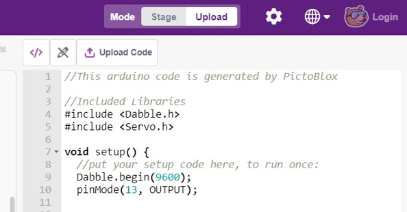
Uploding in the progress.

Code Explanation:
This arduino code is generated by PictoBlox, first in the void setup I assigned pin 13 as an output now the Arduino know that pin 13, or led, will act as an output. Then I setup the code, to run repeatedly, this will set pin 13 HIGH, or ON, meaning that while it is high it is outputting voltage. then wait for 2 milliseconds then turns the LED off after 2 milliseconds delay.
The bulied in LED NOW blinking. Code Files:
Contorolling LED with Bluetooth
In the project I will complate with PictoBlox to program the Arduino to control an LED with Bluetooth. The HC-06 is a class 2 slave Bluetooth module designed for transparent wireless serial communication. Once it is paired to a master Bluetooth device such as PC, smart phones and tablet, its operation becomes transparent to the user. All data received through the serial input is immediately. It has four main pins.
Bluetooth HC-06 module Pin Wiring:
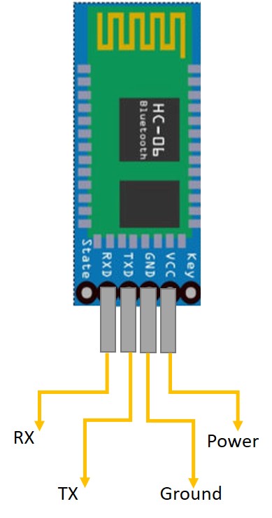
GND is the ground and VCC is the power. The module receives the serial data from the master device (smartphone) through the RXD pin and then transfers that data to the arduino using the TXD pin.
Components needed:
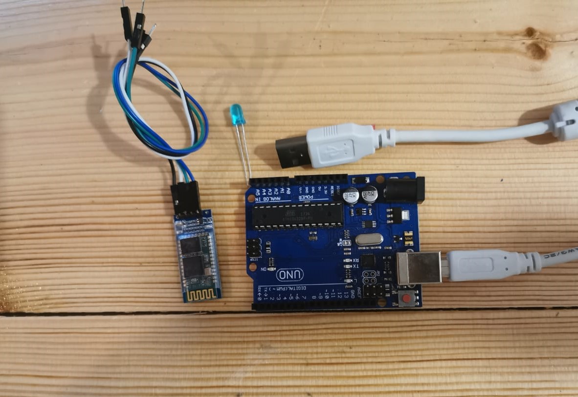
Connctions of the components:
First connect the Bluetooth module to Arduino UNO, to pair our smartphone with Uno via Bluetooth.
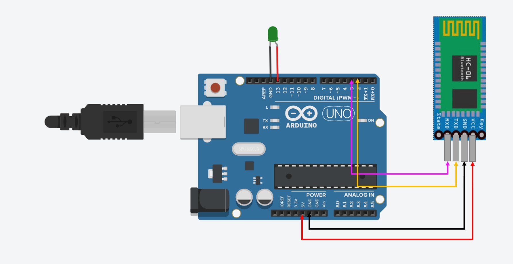
The simulation drowing of the circuit.
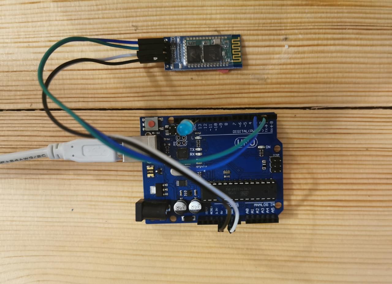
All the Components are Conncted.
Coding
Write the script by using Blocks.

It should be like below.

Always make sure to cross the RX and TX lines between serial devices.


Keep testing and try as much as you can it easy to code and suitable for different ages.

Code Explanation
This arduino code is generated by PictoBlox, first I define for the arduino the Libraries for the blutooth program Dabble. In the void setup the dabble begin, pin 13 is the output. The blutooth will contorl the LED brightness.
Code File:
Processing
In the coming projects I will show you how I applied UI program Processing, with different UI applications.
What is Processing Software?
Is an open source graphical library and integrated development environment built for electronic arts, new media art, visual design communities with purpose of teaching on-programmer the fundamentals of computer programming in a visual context. Processing uses the Java language with graphical user interface for simplifying the compilation and execution stage. The Processing language have been the precursor to other projects including Arduino.
processing
Controlling by using PC mouse
First thing I tested was controlled something by the PC mouse, I downloaded processing program from Here.
I opeend the processing website, then I clicked on tutorials, after I took overview of the applications, I chose to test Arm from category transform.
Components needed:
Code
I copied the code to processing programming environment.
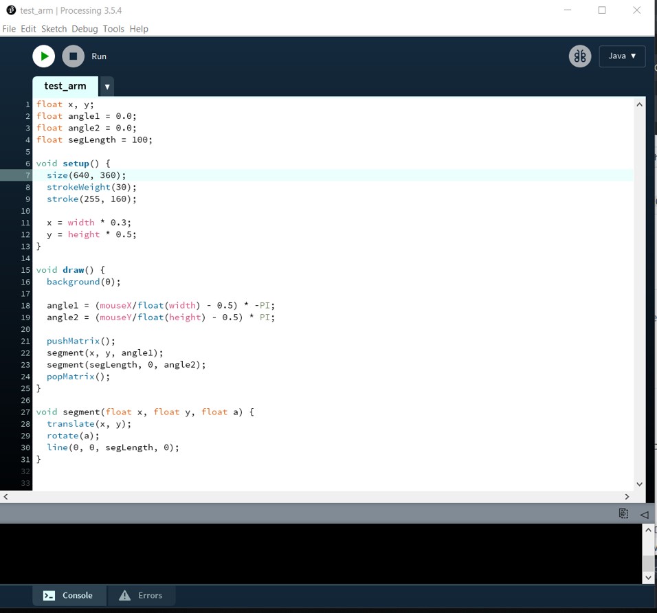
Code explanation In this code the programmer set tow float -arms- the X Y also the segLength 100 we can do adjustment and make it longer or shorter, the in foid setup the size of the test screen and the size of the tow arms stroke. In thw void drow calcution of the movement
The angle of each segment is controlled with the mouseX and mouseY position.The transformations applied to the first segment are also applied to the second segment because they are inside the same pushMatrix() and popMatrix() group.
I tried to changed the code, by increasing the strok size and weight.
Code File
- Arm Code
- Arduino.
- USB cable.
- Potentiometer.
- The first pin goes to GND.
- The second pin goes to analog input 0.
- The third goes to V5.
- Arduino Uno.
- Bluetooth module HC-06.
- RGB LED.
- 3X 220ohm resistor.
- Jumper wires.
- Breadboard.
- Download the controlling app to your smartphone.
Controling App - Connect COMMON pin to GND.
- Connect green to 220ohm the to pin 10.
- Connect Blue to a 220 ohm the pin 9.
- Connect red to a 220 ohm the pin 11.
- Connect blutooth medule:
- VCC to 5v.
- GND to GND.
- Blutetooth module TX to Arduino RX.
- Bluetooth module RX to Arduino Tx.
- Connct the Arduino to your PC.
- Open the smartphone blueooth and search for H06 to do pairing. If it asks a password, it’s 1234.
- Open the app.

Coding
Uploaed the code to your Arduion and you should disconnect the TX and RX cables from the Bluetooth module.
- Select your Bluetooth module and by click on connect bluetooth,then move the slider and click on change color to set your RGB LED color to the selected color.
I did not got all the colors from the first time, I changed the LED connection to Common cothod by conncting the longer lead to GND.

Code explanation:
I explaind the code by addding comments.
Code File
Group assignment
I really have enjoyed trying new things throw this assignment.
Controlling graph
Moving to new example, here I tried to control the graph in my computer, this is called as I read serial communication because the connection appears to both the board and the computer as a serial port, by using a USB to serial converter. Here I will use Processing to see the serial monitor instade of the Ardino serial monitor.
Components needed:
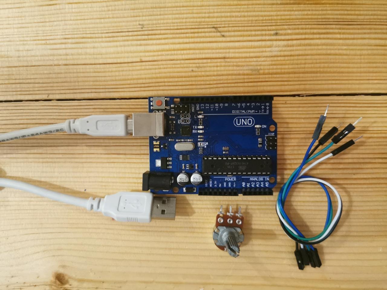
Connctions of the components.
First connect the Potentiometer to the Arduino
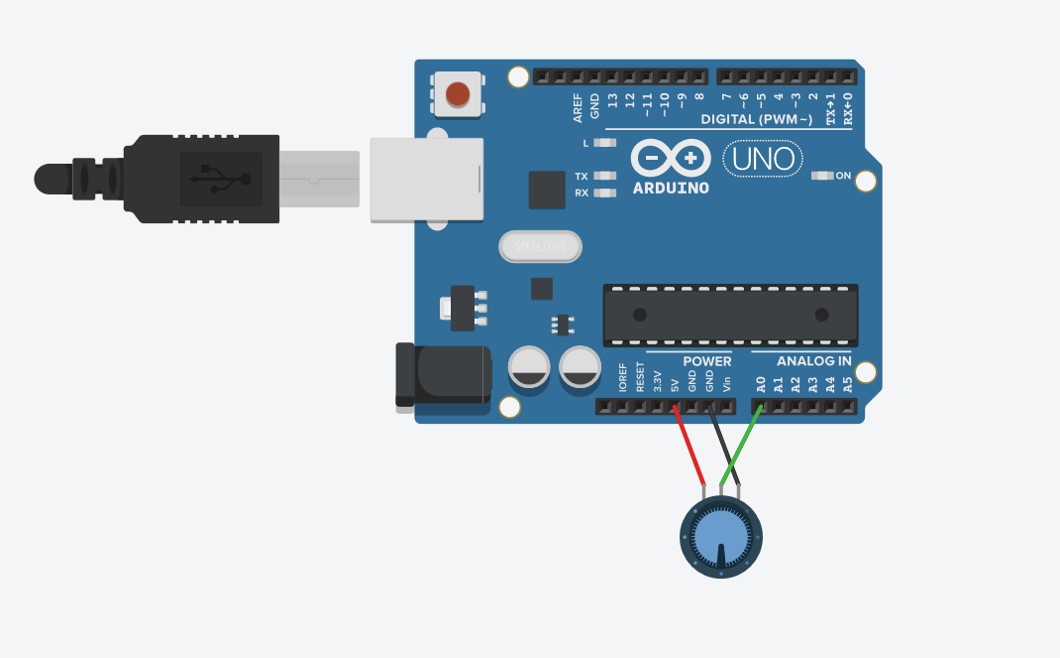
The simulation drowing of the circuit.
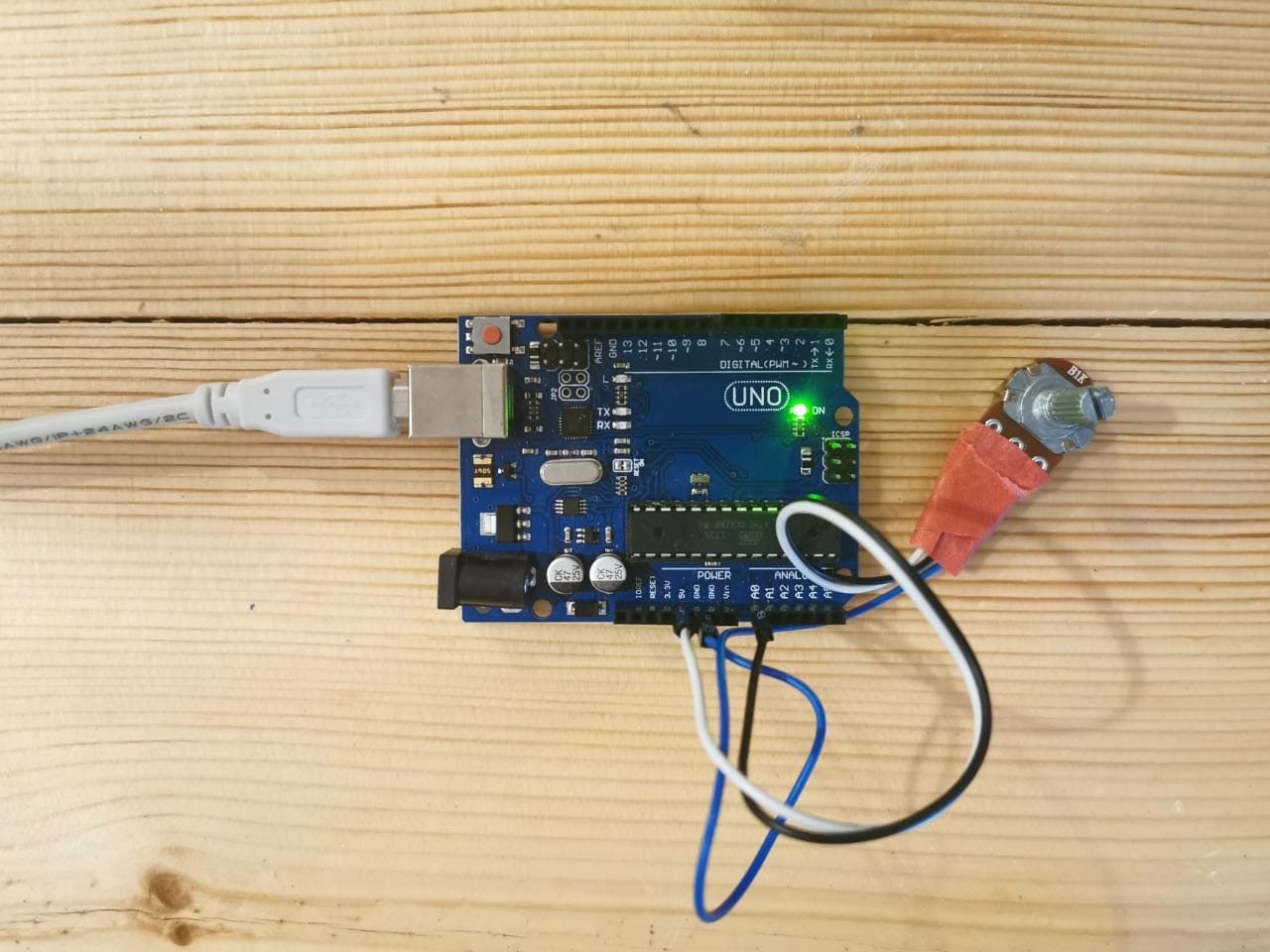
After conncted all the components.
Coding
Upload the code to Arduino.
Code explanation
I explaind the code by addding comments.
Upload the code to Processing.
Code explanation
I explaind the code by addding comments.
Graph by Arduino
Code File:
Controling RGB LED by Smartphone Bluetooth and Arduino
In this project I will show you how to interface the Arduino with smartphone, I tried to control the color of an RGB LED with smartphone via Bluetooth.
Components needed:
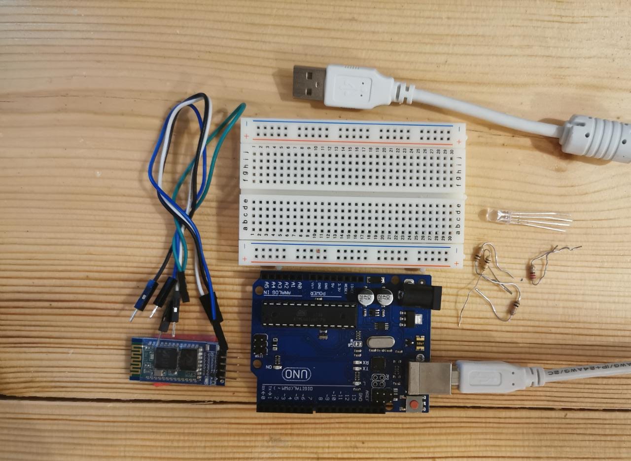
Connct the RGB LED to Arduino:
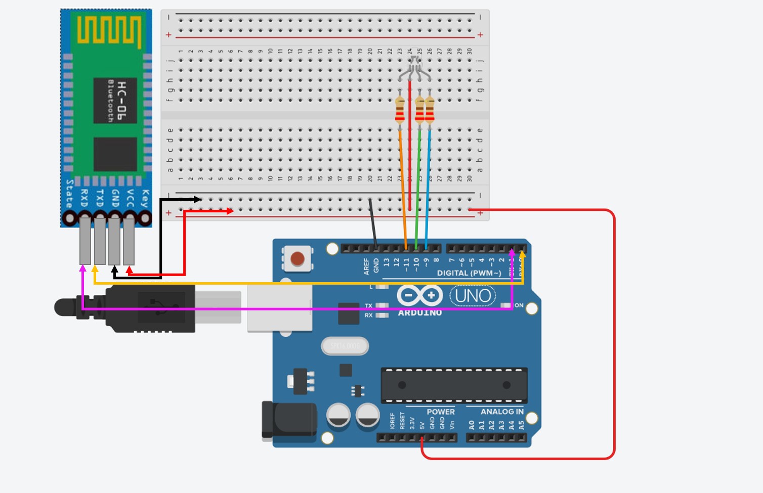
The simulation drowing of the circuit.
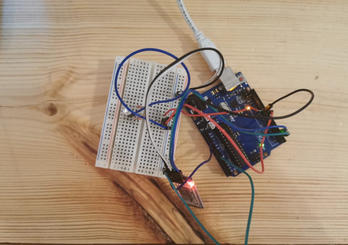
After conncted all the components.