week_18
Project Development
Complete your final project, tracking your progress:
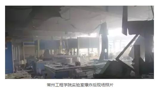
In China, electricity safety is a serious problem, especially in recent years, there have been a number of electricity safety accidents, which have caused a great loss of personnel and property.
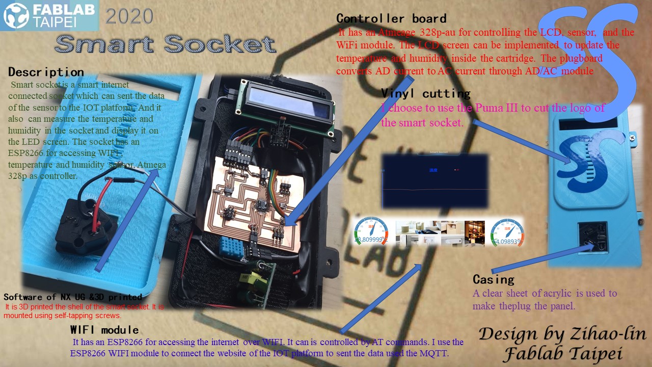
I want to make a device that can display the temperature and humidity inside the socket in real time and transmit the data to the Internet of Things platform for data statistics. I would give the project a name: SS_ Smart Socket.
SS _ Smart Socket has a unique design made of 3D printer, which has an LCD screen can implemented to update the temperature and humidity inside the socket. SS _ Smart Socket also has an WIFI module, which can connect the website of the IOT platform to send the data of the sensor by using the MQTT.
I will also use WIFI module to remotely control the switch of smart socket.
-- ① control the switch of smart socket in certain time in a day automatically.
-- ② control the switch of smart socket when I want to.
The change of temperature and humidity intensity inside the smart board can be viewed in real time in two ways.
-- ① an LCD screen on the smart socket.
-- ② IOT platform.
The present of most smart sockets (such as xiaomi smart sockets and Huawei smart sockets) can only achieve timing switch and remote control, but cannot be smart switch according to the illumination.
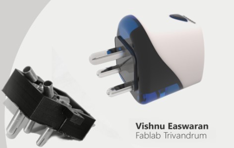
A student in Fab Academy 2016 Easwaran also made a WIFI /internet-controlled power socket which can be plugged into any of the existing ones. So, the devices connected to these can be remotely switched on and off. He used the ESP8266 Wi-Fi Module for networking and used Atmega 328P as the controller.
For sensors and microcontrollers, I will use a small Atmega 328P system designed by myself, along with a traditional Arduino temperature and humidity sensor and OLED display, to detect and display the temperature and humidity inside the smart plug-in board.
I plan to use the Atmega 328P-AU microcontroller and ESP8266 WIFI control module for my final project. Because these chips have higher cache space and more I/O pins.
The ESP8266 module will be connected to the router and relay module so That I can upload sensor data to the Internet of Things platform for display statistics and remotely control the disconnection and closure of the intelligent plugboard relay module.
I will also send instructions and receive information to my smart plug-in board on the interface of the mobile Internet of Things platform.
| Qty | Description | Price |
|---|---|---|
| 1 | ESP8266 module (include relay module) | ¥26 |
| 1 | Atmega 328P-AU | ¥7.12 |
| 1 | PAcrylic Plate (laser engraving) | N/A |
| 1 | PLA (3D Printer) | N/A |
| 1 | Temperature& Humidity Sensor (DHT11) | ¥5.61 |
| 1 | OLED Screen | ¥15.47 |
| 1 | DA/AC module | ¥10.15 |
| 2 | 0.1 μf Capacitance | N/A |
| 2 | 1kΩ resistance | N/A |
| 2 | LED (green and red) | N/A |
| N | pinheaded | N/A |
| 1 | 20M oscillator | N/A |
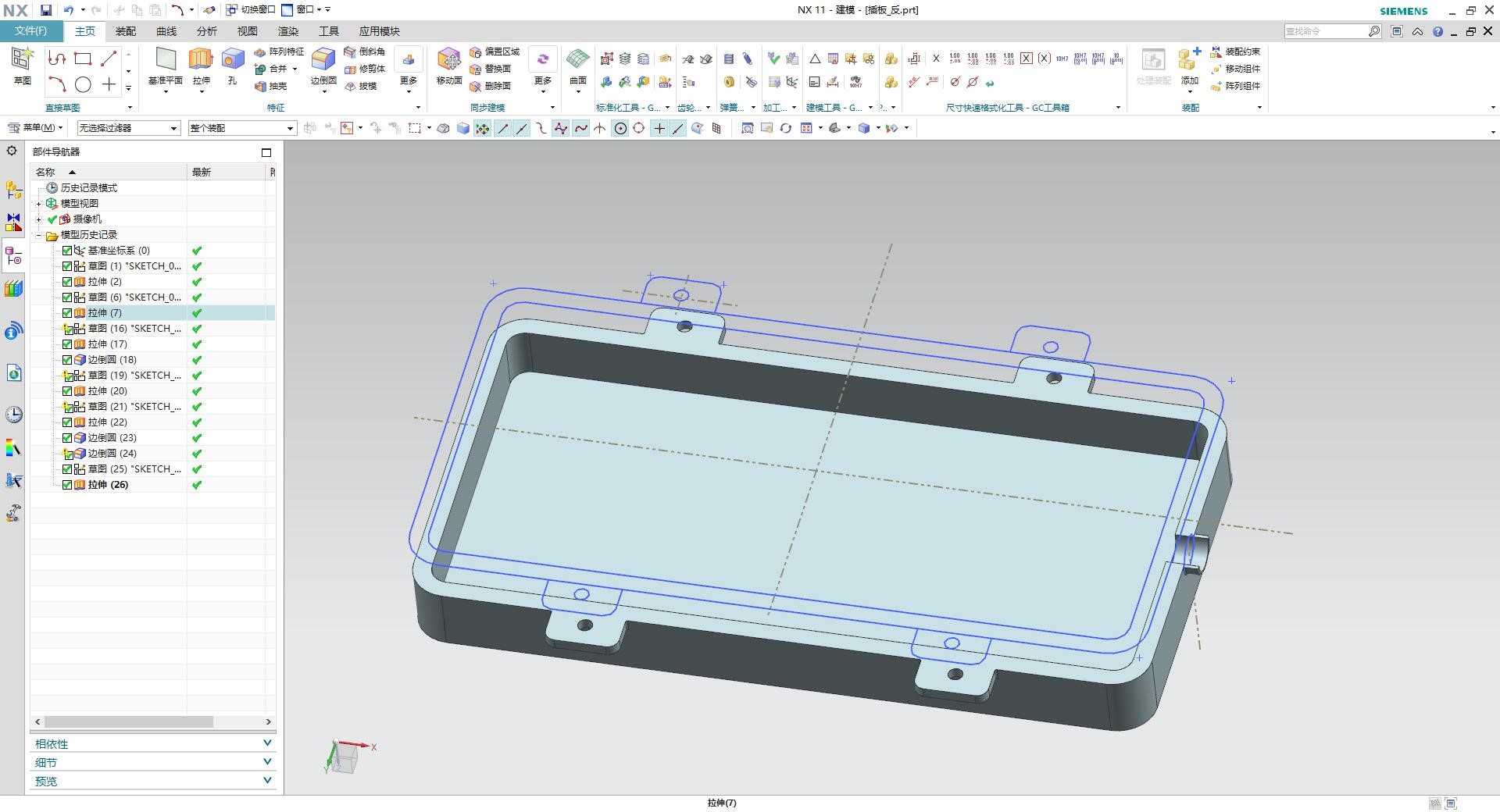
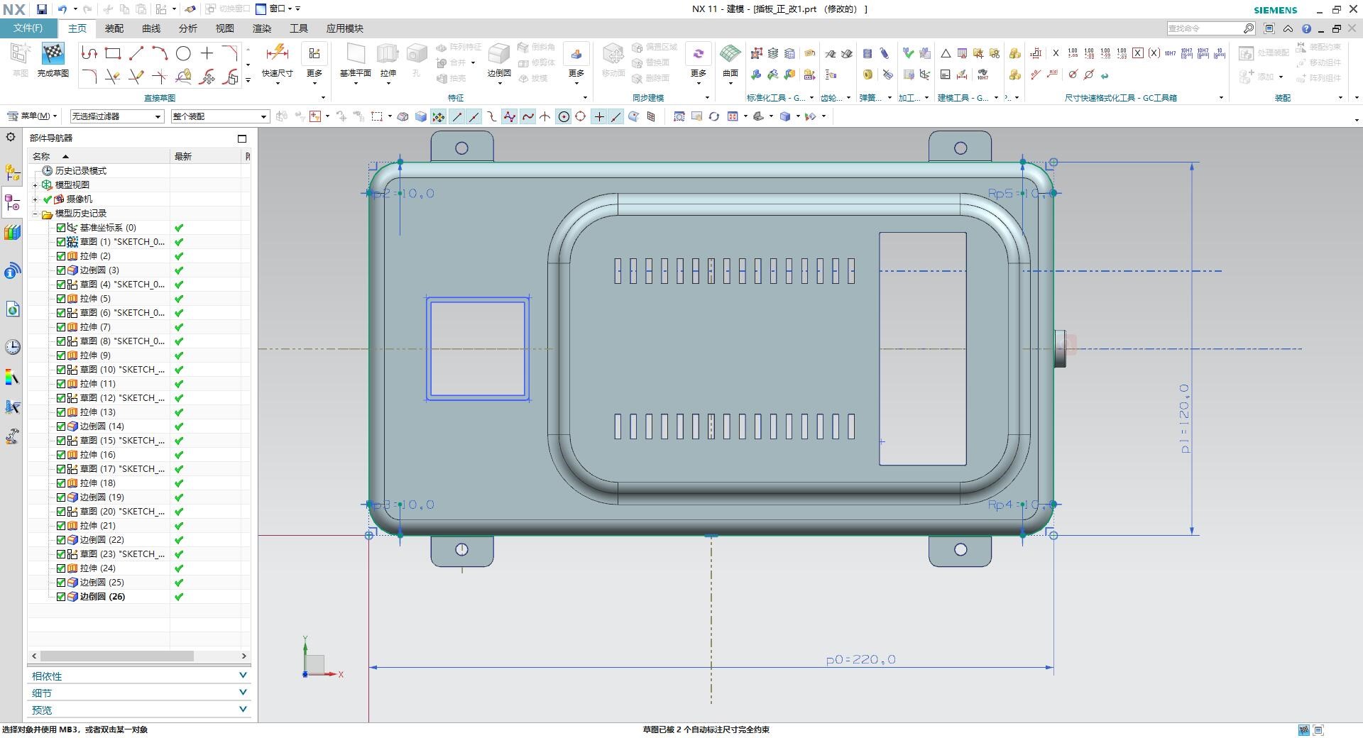
I have designed smart socket by using software of NX UG. It combines two parts: upper box and bottom box. The upper box covers an OLED screen displaying real-time temperature and humidity and a plug panel. The bottom box covers the sensors and microcontrollers.
⑴ Upper Box
① To start creation, we should sketch the base of the part. After that, we can add some preliminary sketch of the object. We should choose the dimension and chose the form.
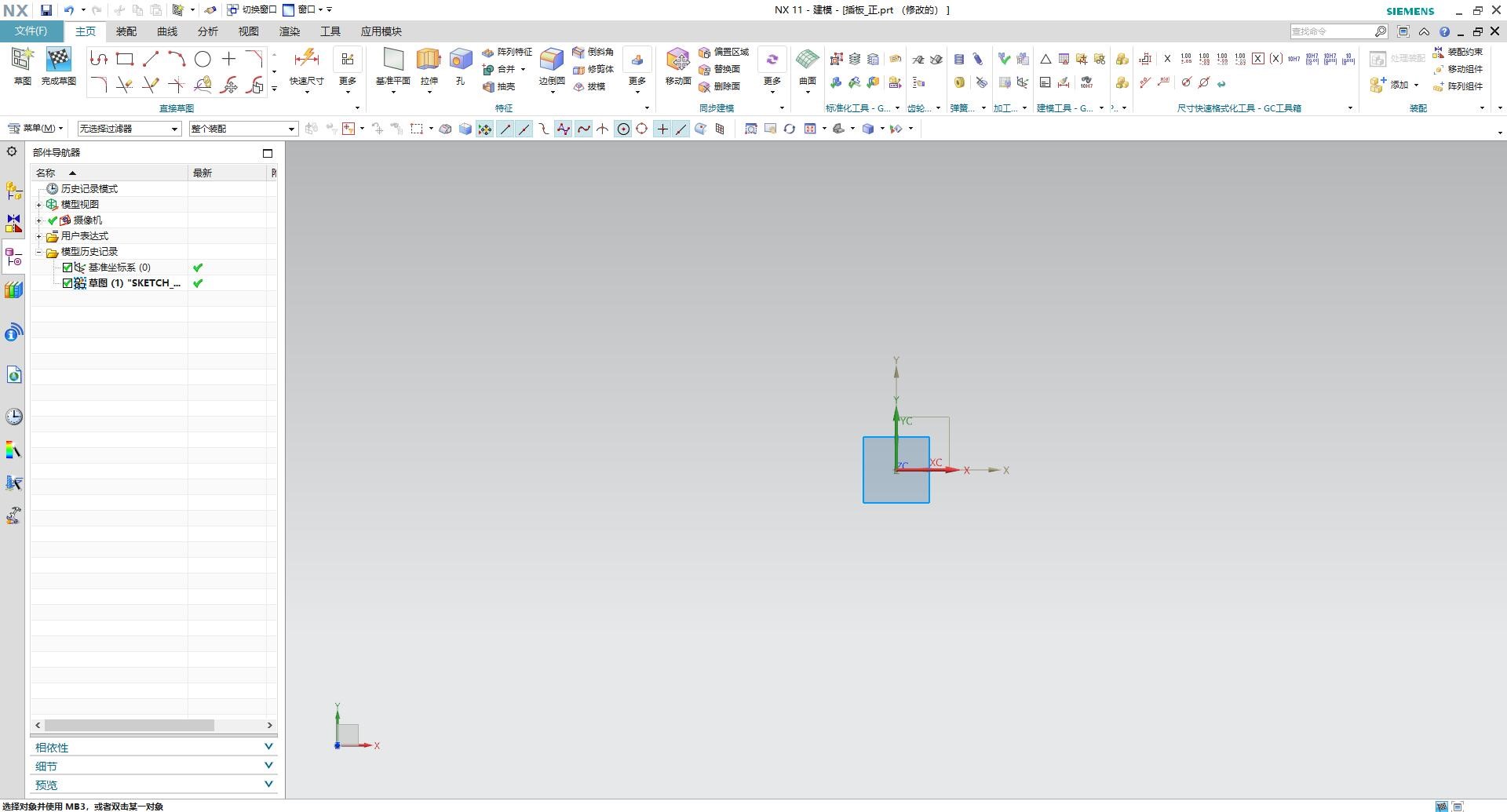
② My part should look like a square. Therefore, to draw the base, I have chosen “Rectangular”. I also used “arc chamfering”.
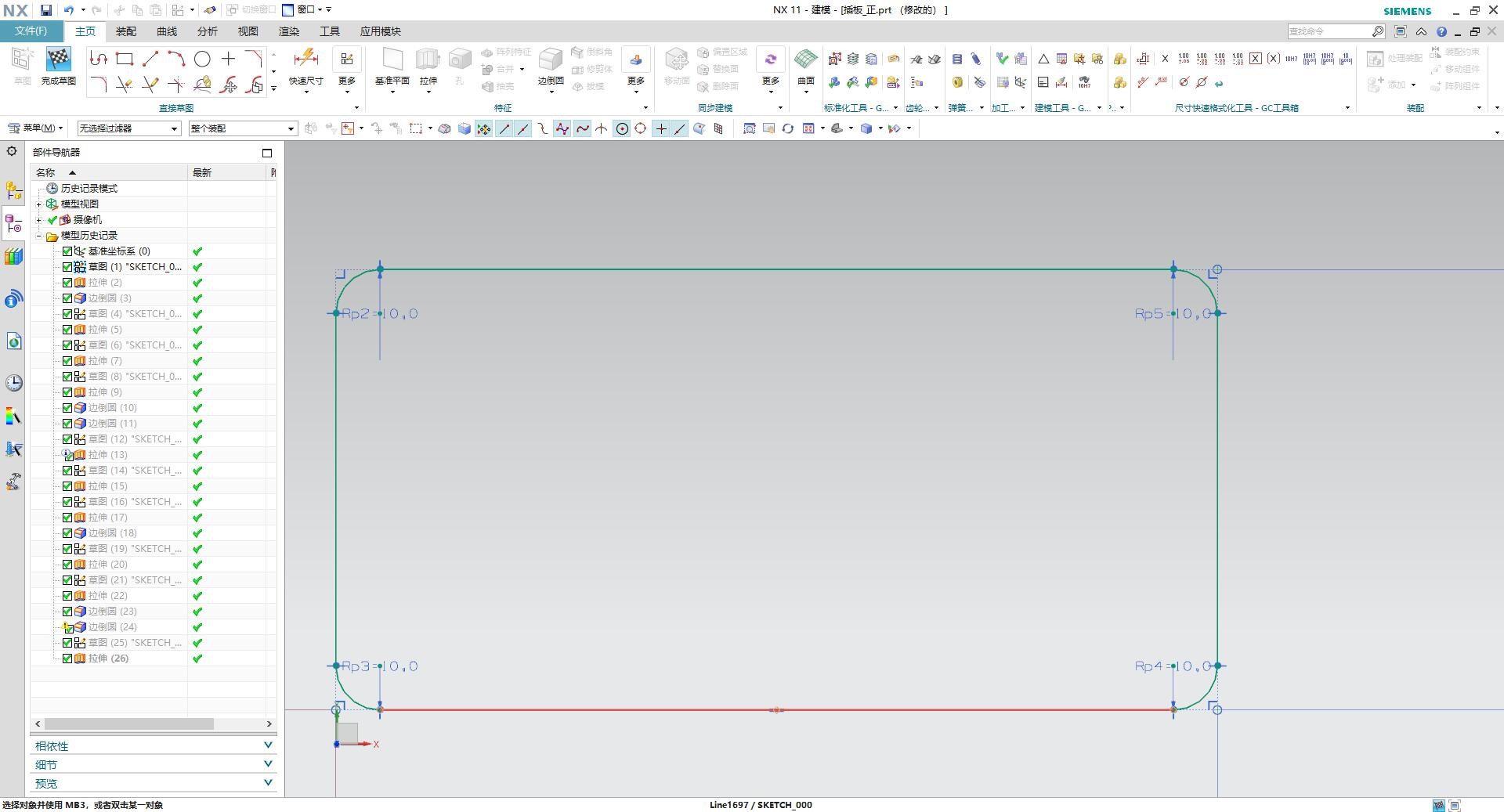
③ After the sketch is finished, I can extrude it to necessary shape.
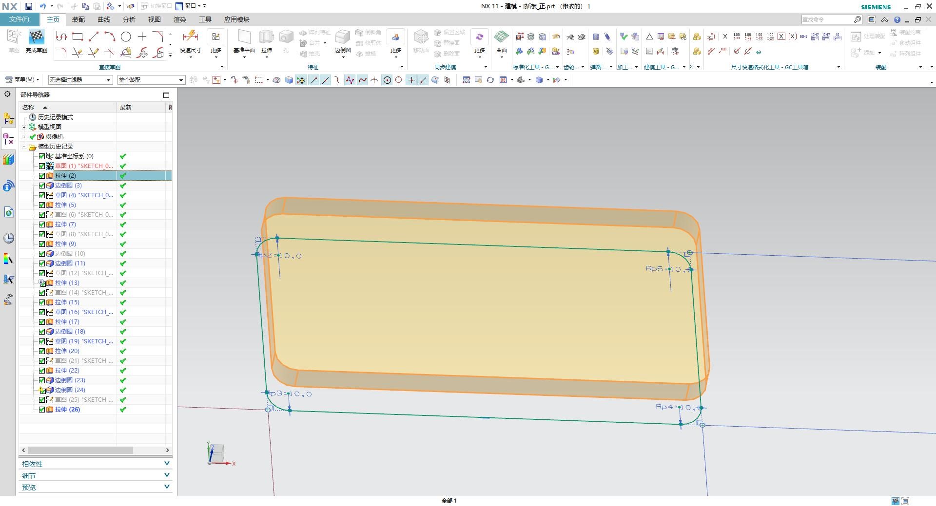
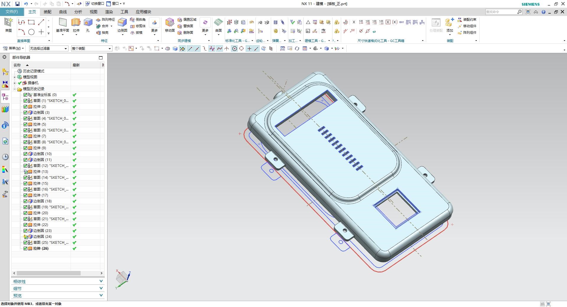
④ I can add some specific shapes to this part in the same way. After all parts are ready, It seems like this.
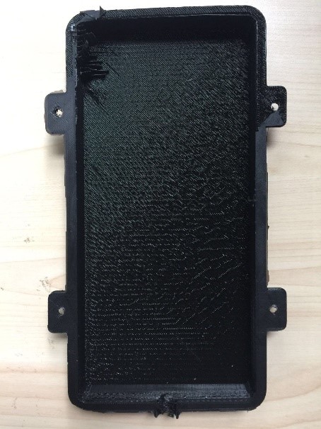
⑵ Bottom box
I basically used the same modules and instructions to design the bottom box. It seems like this.
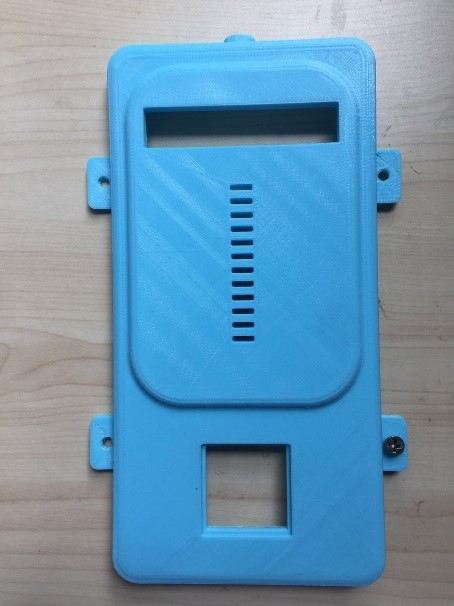
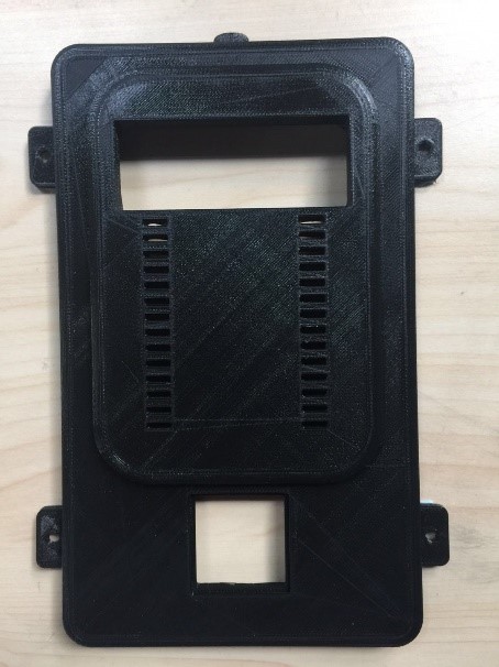
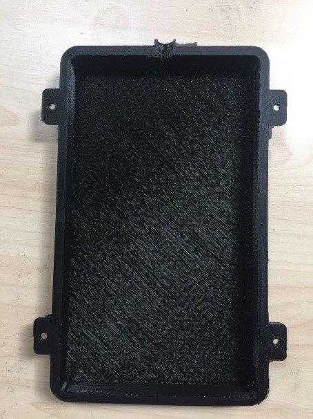
⑶ 3D printer
The upper and bottom boxes are connected and locked by 4 self-tapping screws.
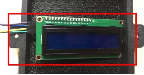
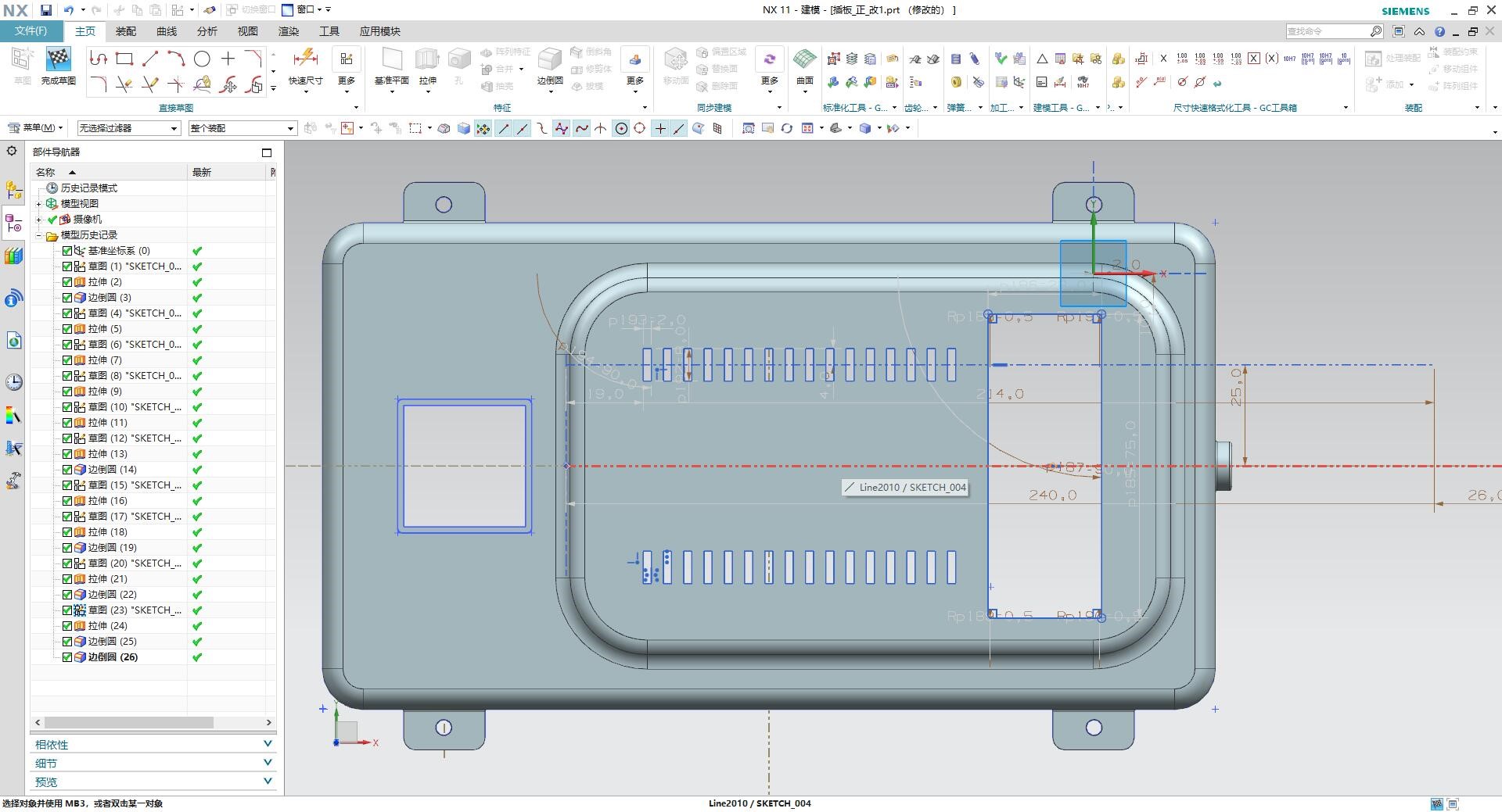
⑷ Modification
When I placed the LCD screen on the upper box, I found that the smart panel housing width and LCD screen hollows were small, and the DuPont line and LCD screen could not be lowered. I modified the above problems on UG software to form the second version of smart cartridge housing.
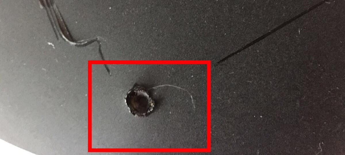
When I used 3D printing, I found that the 3D printer would move down in one of the places abnormally. After checking the program, software and 3D printer, it was found that the smart plugboard I designed exceeded the limit of the 3D printer in terms of length. Therefore, I can only shorten the long edge of my board to 200mm.
⑸ Final project of the box
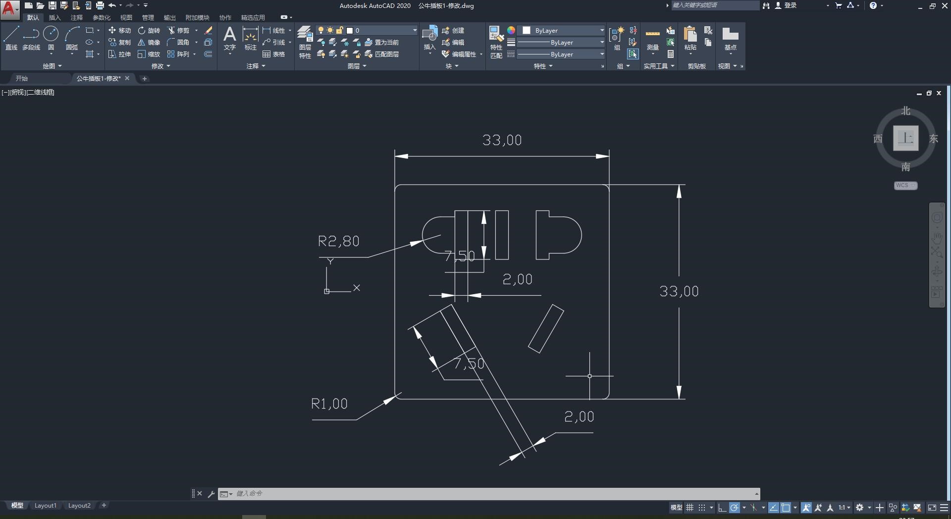
I used AutoCAD for the design of the panel of the smart socket. I searched on the Internet for the national standard document of China -- "Types, Basic Parameters and Dimensions of three-phase plug Sockets for Household and similar Purposes”. According to the relevant requirements, the type 86 five-hole panel is designed.
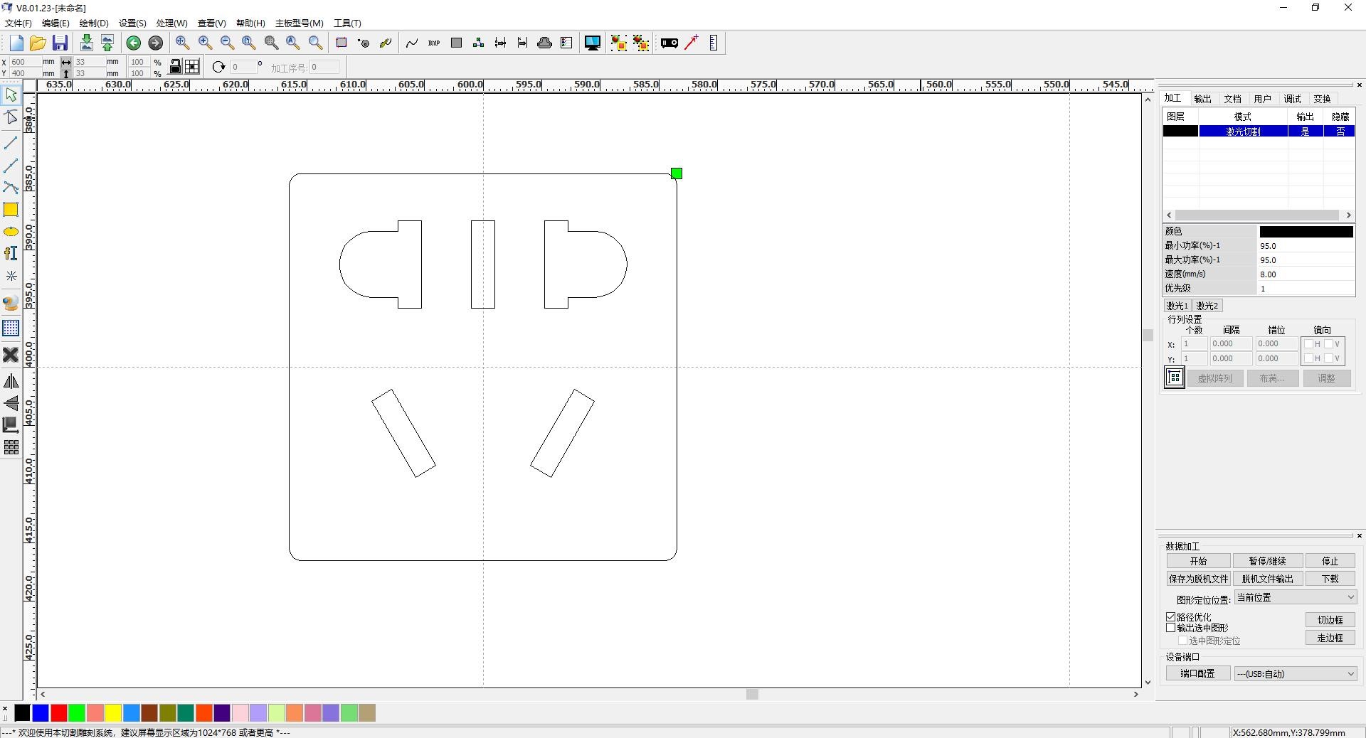
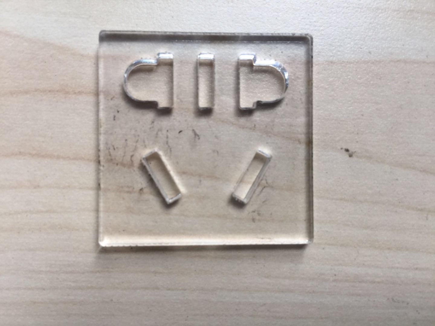
After I have designed the plug panel, I plan to use a 3mm transparent acrylic panel for laser cutting. Therefore, I set the laser cutting parameters on the RDworks software, as shown in the figure below. I use the best combination is speed 10 mm/sec and intensity 95 percent.
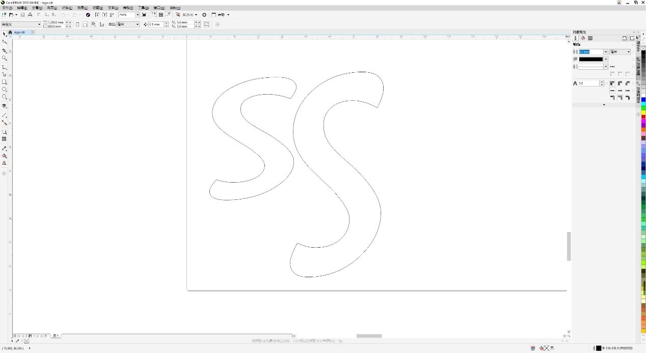
I used Crodraw for the design of the logo of the smart socket. I want to use SS to represent the smart socket, so I use SS as my logo.

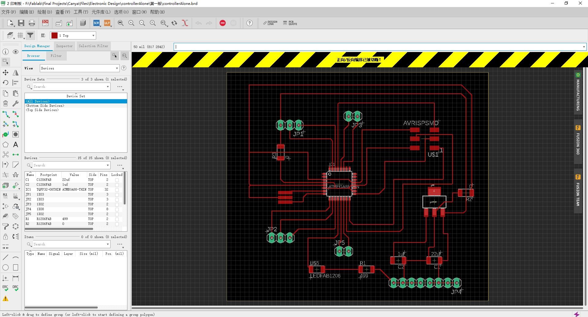
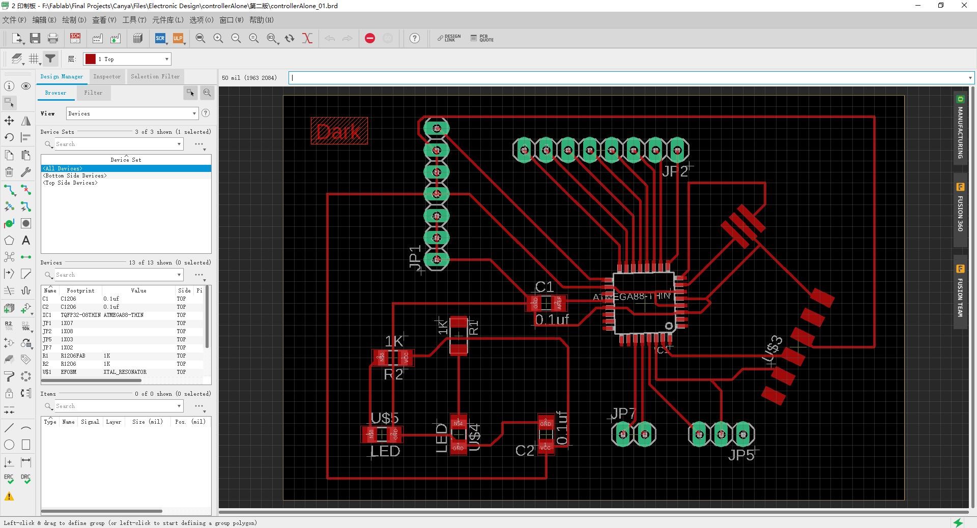
I started off by having controller in one board and the ESP8266 and AC/DC model on another board. First of all, I learned relevant circuit design manuscripts from Easwaran who is the student of fab Academy 2016'. The board comprises of Atmega 328p, Control lines to AC/DC, ESP8266, LCD screen, DHT11 model, some pinouts for debugging, the 3.3V buck.
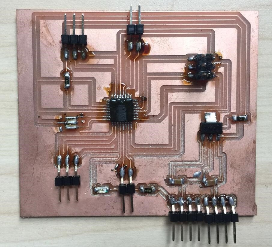
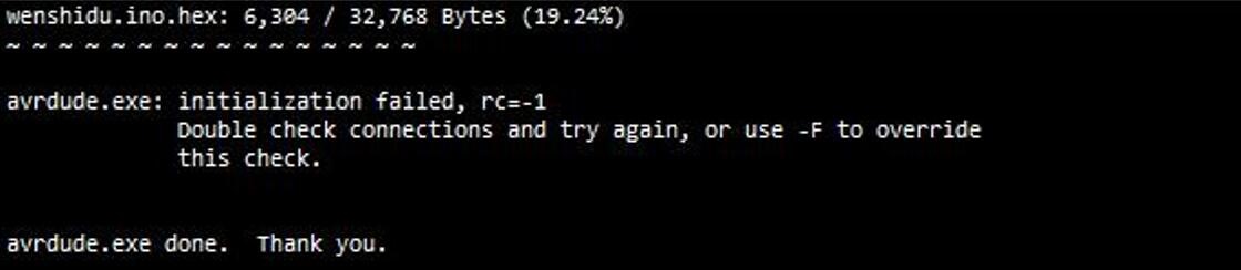
After soldering on the components and I was not able to flash the controller. While trying to flash the controller, it told me that the microcontroller cannot be identified, please check the circuit. I used a digital multimeter to check the circuit conduction of PCB components and the corresponding values of resistance and capacitance. No abnormal conditions were found. However, PCB has abnormal heat in the 3.3V buck and ISP, so I wonder if there is something wrong with my board design. Instead I decided to redesign an Atmega 328P minimal control system.
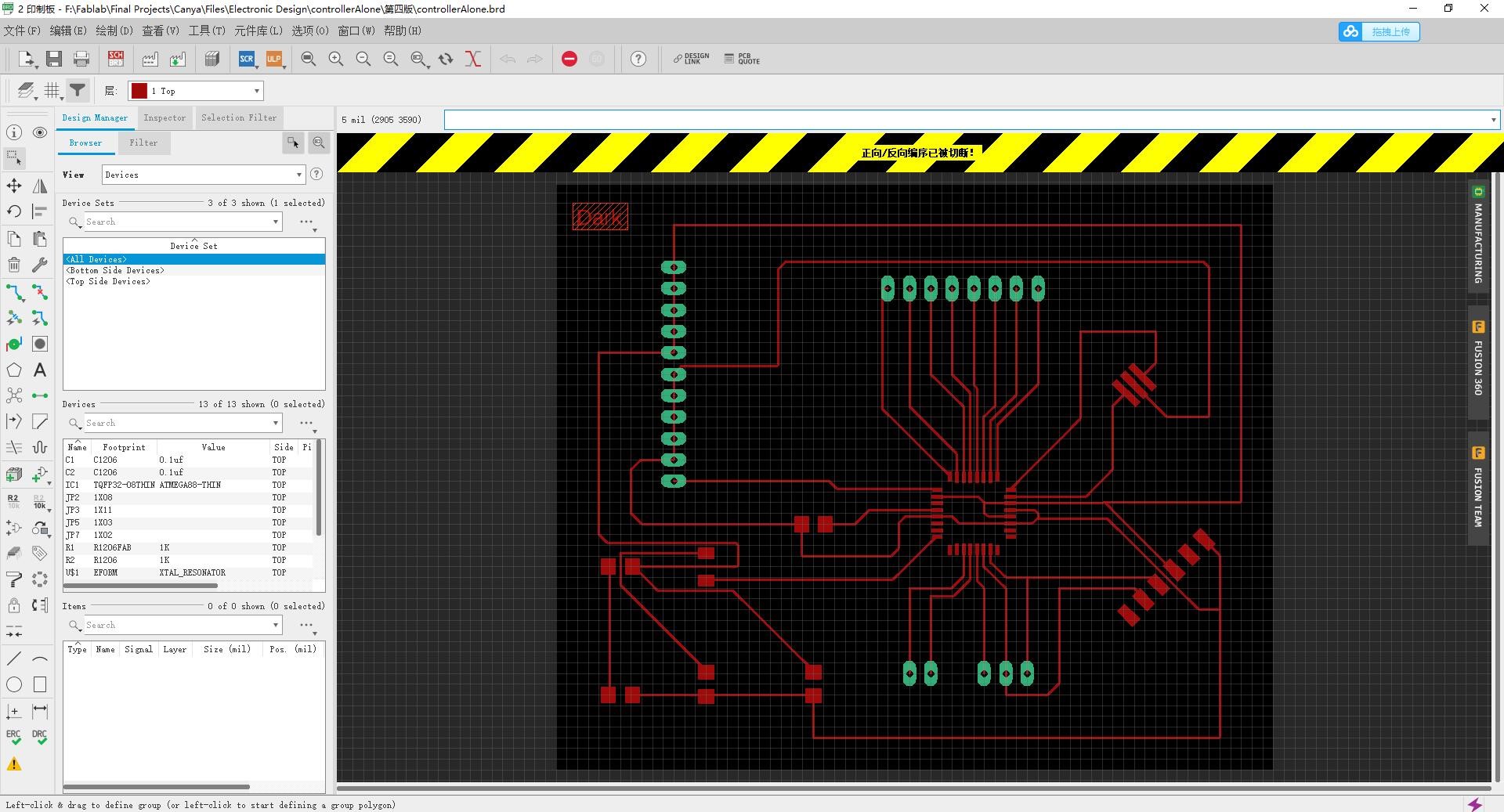
I found that LED_2 lamp was not connected with the micro-controller in my PCB, that is, the LED lamp lost its function, and VCC and GND connectors were relatively few, so the conversion connector between VCC and GND was added.
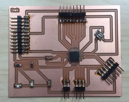
So I started making my third PCB.
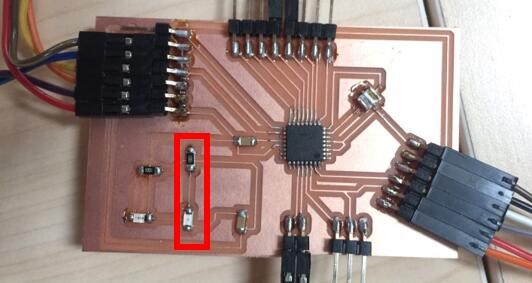
So I started making my third PCB.
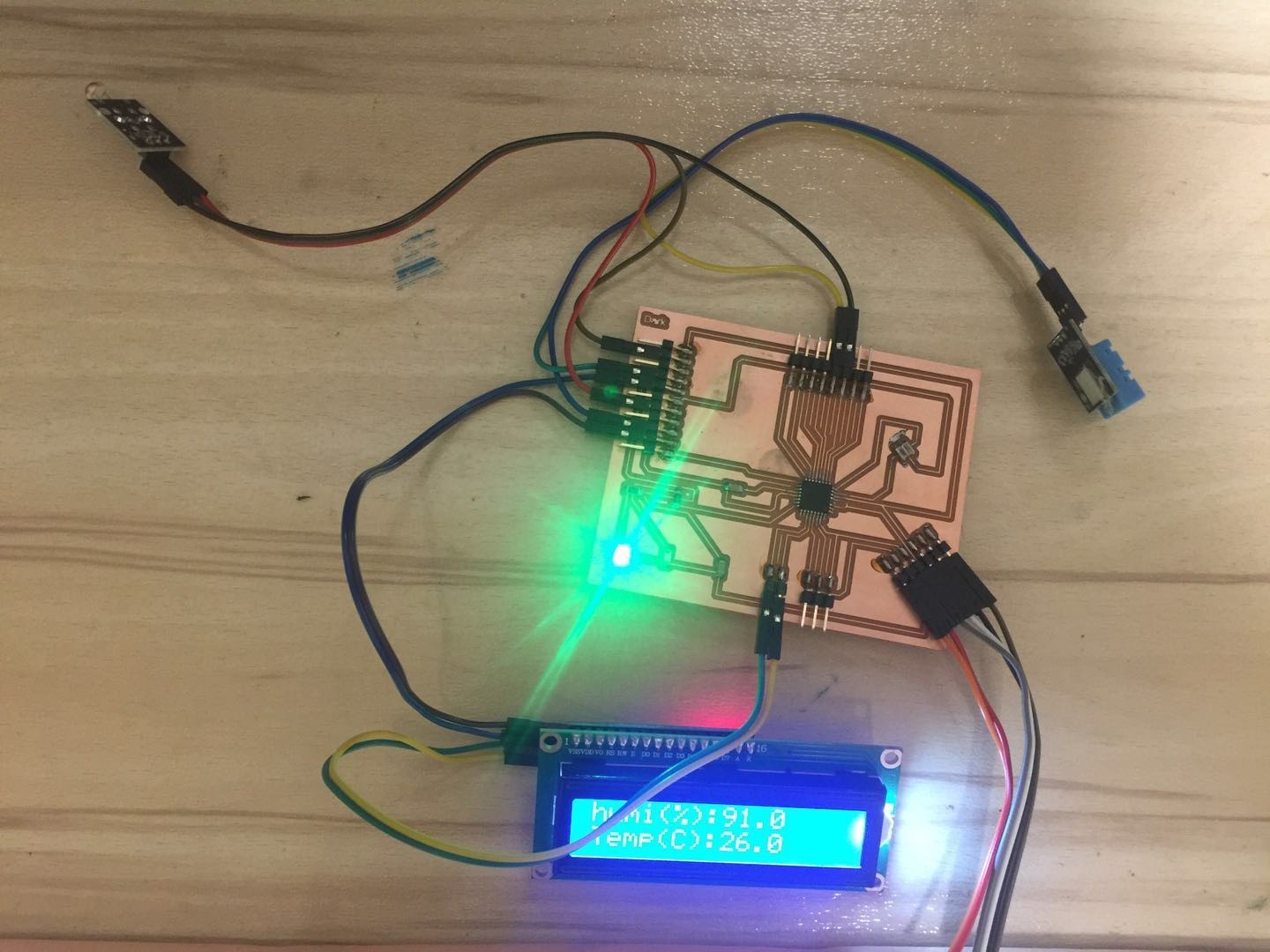
After getting the board ready for programming, modify the written code for the new controller upload it. Firstly, I connected the LCD screen, temperature and humidity sensor, and photosensitive sensor to verify whether the PCB board could work normally. Here is the Arduino code of the controller.
                    #include

                    #include "Wire.h" // Import the libraries needed to drive the LCD

                    #include "LiquidCrystal_I2C.h"

                    #include "dht.h" // Import DHT library for temperature and humidity sensor

                    #define dht_pin 9 // Connect the data port of temperature and humidity sensor to 9


                    dht DHT;


                    // Set the LCD screen

                    LiquidCrystal_I2C lcd(0x27,16,2); // 0x27 is the address of the I2C bus


                    void setup() {

                        // pinMode(LED,OUTPUT);//Set LED to output mode


                      // Delay waits for the system to initialize

                      delay(1000);

                      // Initializes the LCD screen

                      lcd.init();

                      // Turn on the backlight of the LCD screen

                      lcd.backlight();

                      lcd.setCursor(0,0);

                      lcd.print("humi(%): ");

                      lcd.setCursor(0, 1);

                      lcd.print("Temp(C): ");

                    }


                    void loop() {

                      // Read the temperature and humidity sensor data

                      DHT.read11(dht_pin);

                      lcd.setCursor(8,0);

                      lcd.print(DHT.humidity,1);

                      lcd.setCursor(8,1);

                      lcd.print(DHT.temperature,1);


                      delay(1000);

                    }
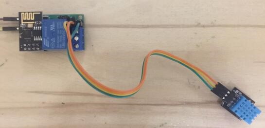
I first used THE ESP8266 WIFI module for the test, connected the temperature and humidity sensor, and uploaded the temperature and humidity values to the Internet of Things platform.
① Line connection: Connect the power cord to the input end of the Internet of Things switch and the DHT11 sensor to the IO port of the Internet of Things switch.
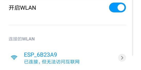
② After wiring is completed, we will conduct an initial configuration for the Internet of Things switch. After connecting the source, the Internet of Things switch will automatically generate an AP configuration hotspot with no password at the beginning of "ESP_". We will open the WIN management page with our mobile phone to search and connect.
③ After successful connection, open the browser of the phone, enter the browser address: 192.168.4.1 to enter the configuration page of the device, and operate according to the prompts on the configuration page. Enter the WIFI name and password where you can normally surf the Internet at home. After the input, we click the code of the copying device, confirm the code of the copying device and click save. The next step is to add devices to the access control side. Pop up the dialog box, find IO01 (R) in the access sensor, and select "DHT11 temperature and humidity Sensor”. Click Save.
According to the previous tests, I did the final assembly and debugging.