week_17
Machine design
This week our group will make a XY plotter drawing robot. With drawing robot, you can draw images on white board and also you can clean images by robot. We reference machine which we found on instructable . We have modified the original project and increased the black panel cleaning function.
Group Assignments Address: http://fabacademy.org/2020/labs/chaihuo/assignment/week17_group/.
For the mechanical part was done by me.
For the software part we used processing, which was taken cared of by Yifei.
For the electronics part we used Arduino, which was taken cared of by Nanjie Chen.
My work in the team is to modify the mechanical structure and increase the demand for black panel cleaning. So, I focused on changing the structure of the gondola file. The original structure is as follows:
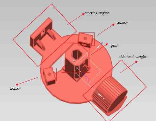
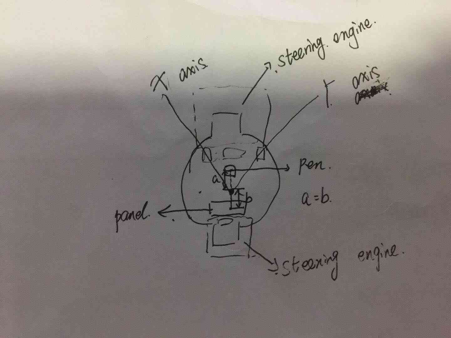
At first, I designed three schemes. The first is to use two steering gear to switch from each other to switch the pen and black panel. The second and the third are to add structure to the original machine to complete the eraser function. Therefore, our team started from the simple and adopted the first plan.
The fist plan as follow:
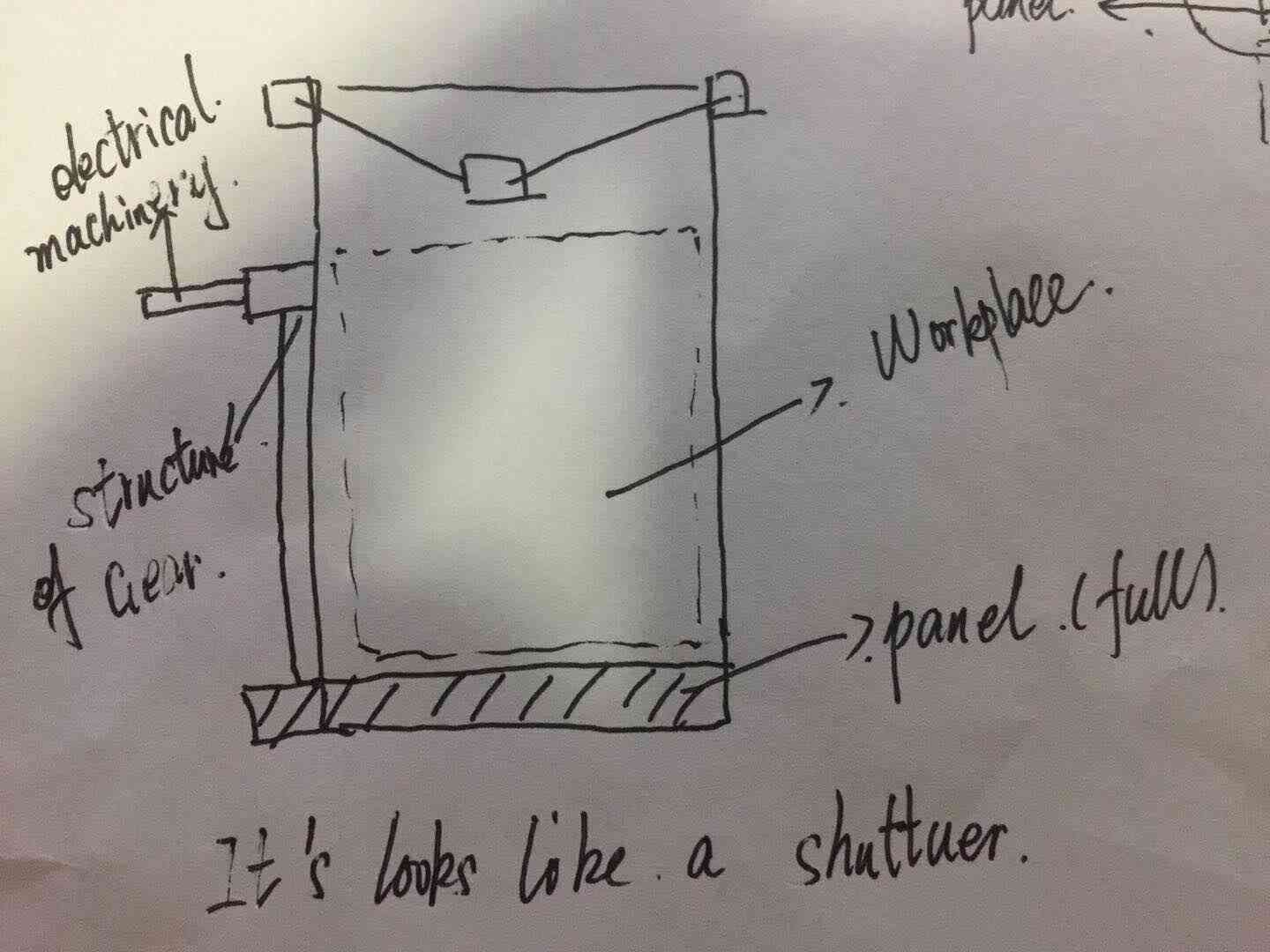
The second plan as follow:
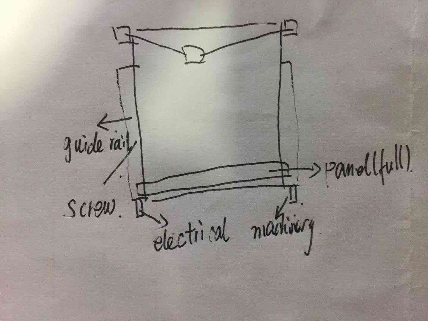
The third plan as follow:
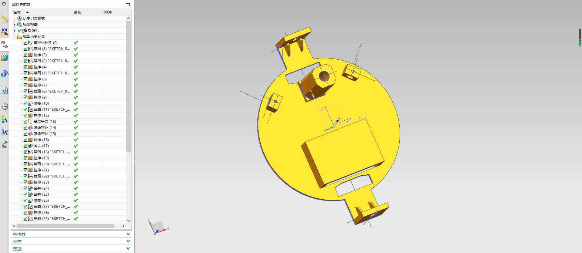
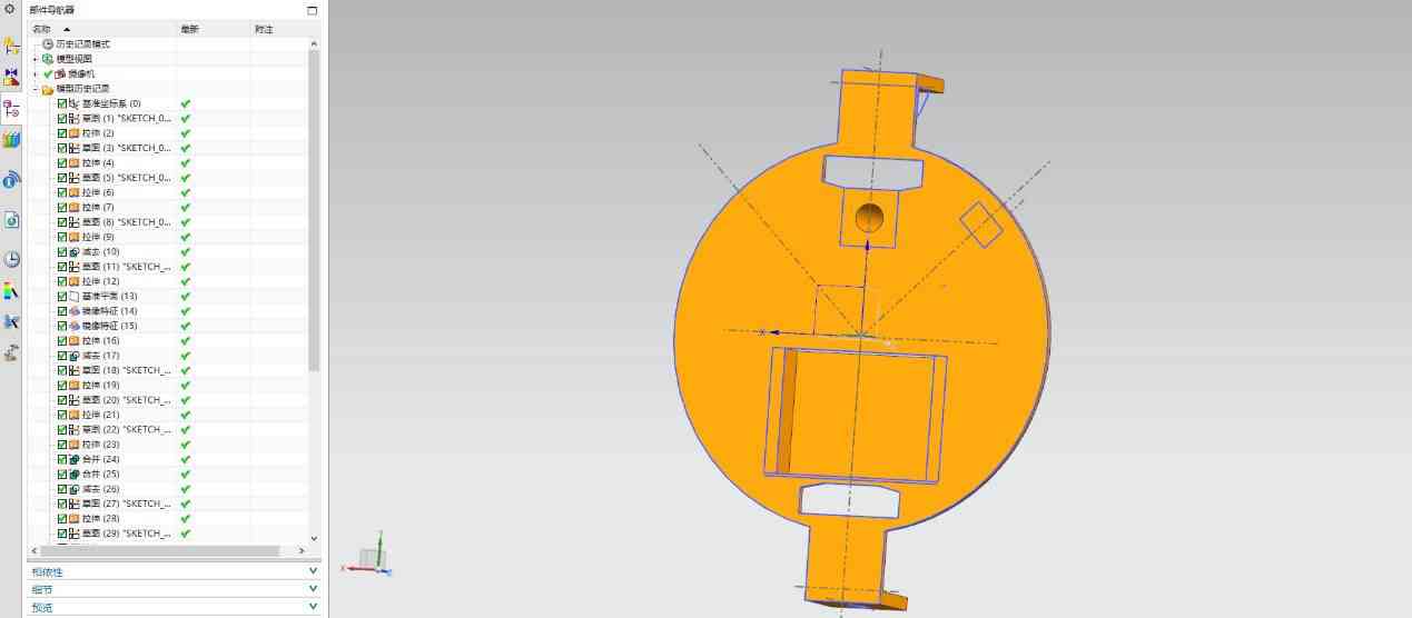
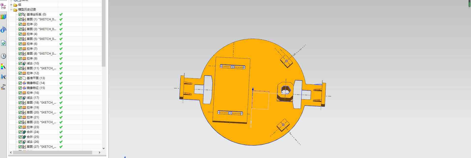
Then I designed the design on UG according to the sketch of the first scheme, and the size of the design part was measured according to the actual mapping and the mapping of the original document.
I used sketching, stretching, mirroring, etc.
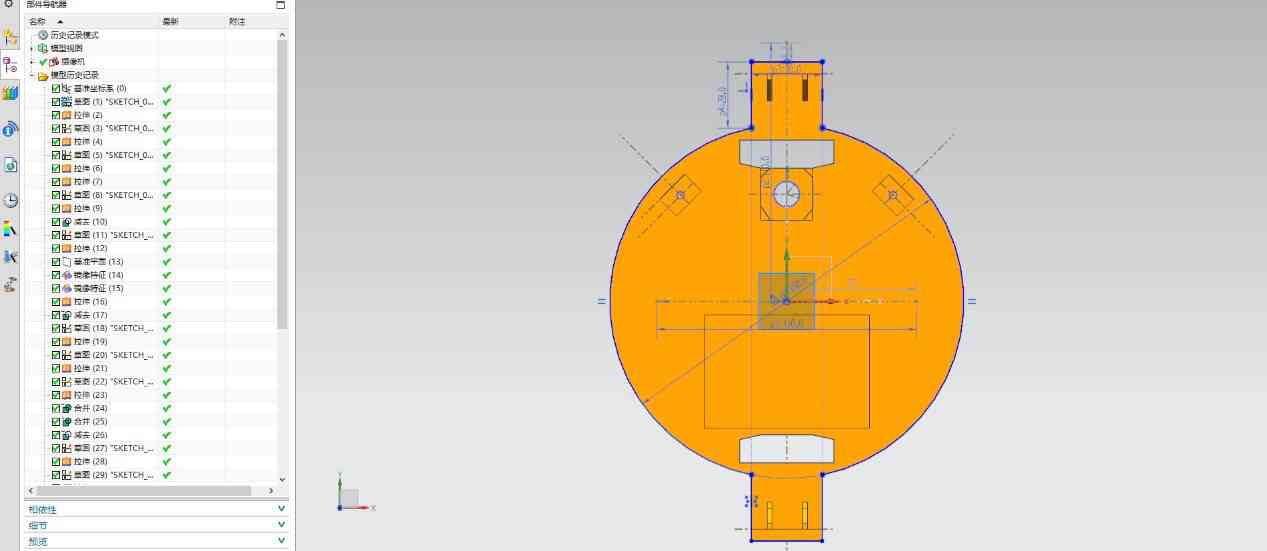
The size of the black plate of this design needs to be cut, the length is 60mm, the width is 48mm, high is 15mm. The black plate is attached to the board with double faced adhesive tape.
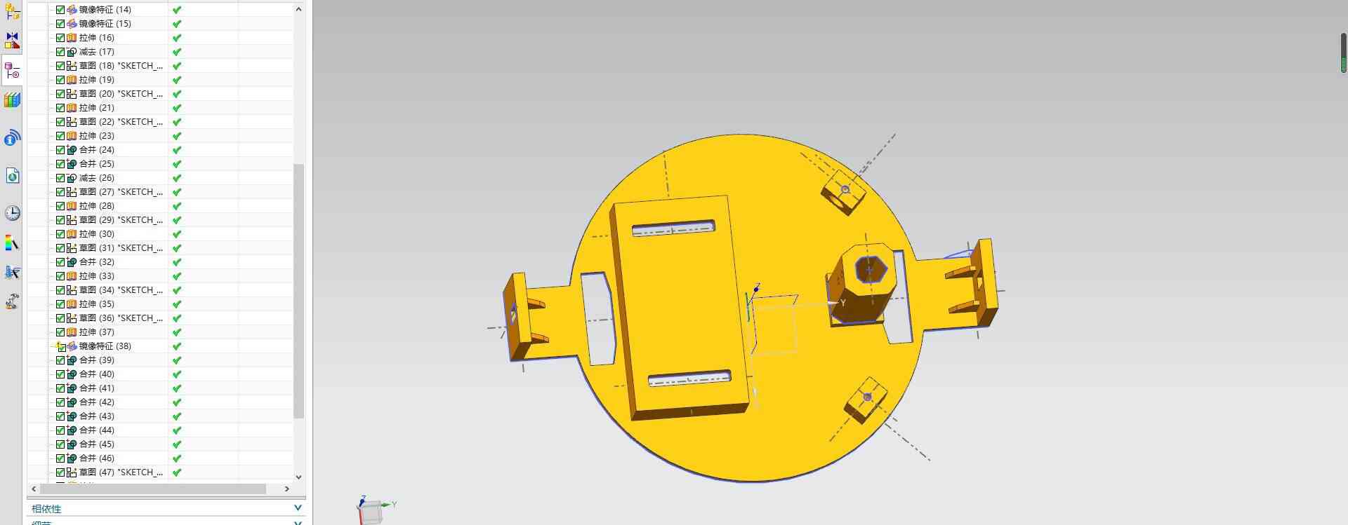
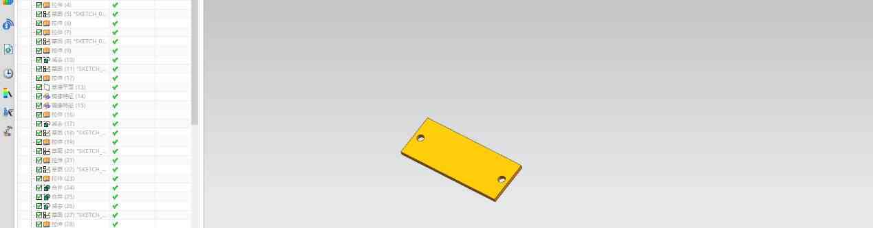
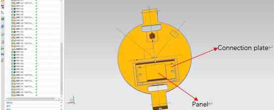
The design of the rubbing parts is not reasonable and the adjustment is repeated. I added a connecting board with a laser cut. Add a 5mm u-groove on the modified component, and the connecting board and the modified parts are connected by 5mm bolts and can be slipped up and down. At the same time, I added the overall size of the modified parts (150mm). The second edition is designed as follows:
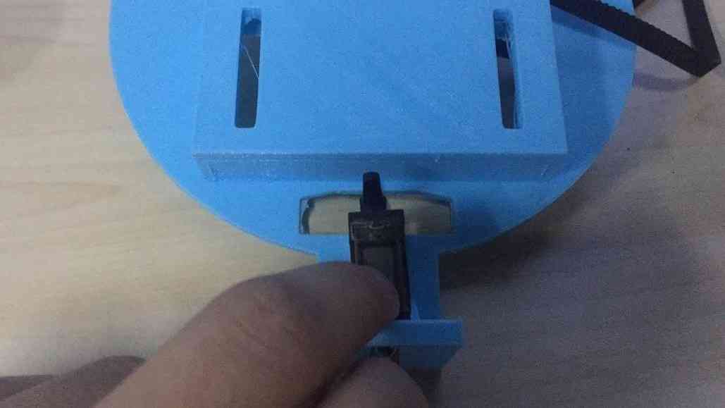
Then I 3D printed the parts, I found a very serious problem, the steering gear part is not considered clearly, need to dig a slot to put the steering gear flat.
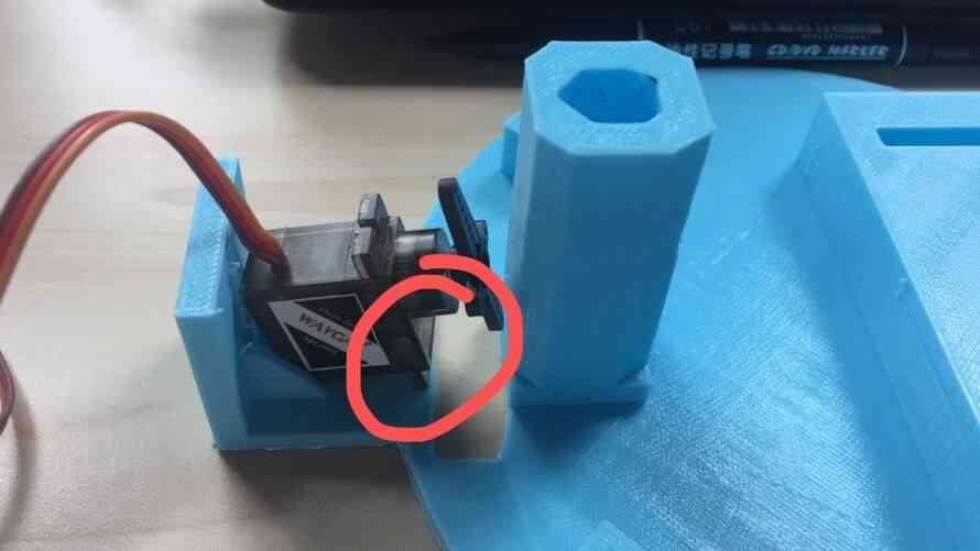
Modify the following:
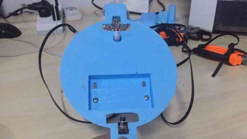
I used two M4 bolt holding pens
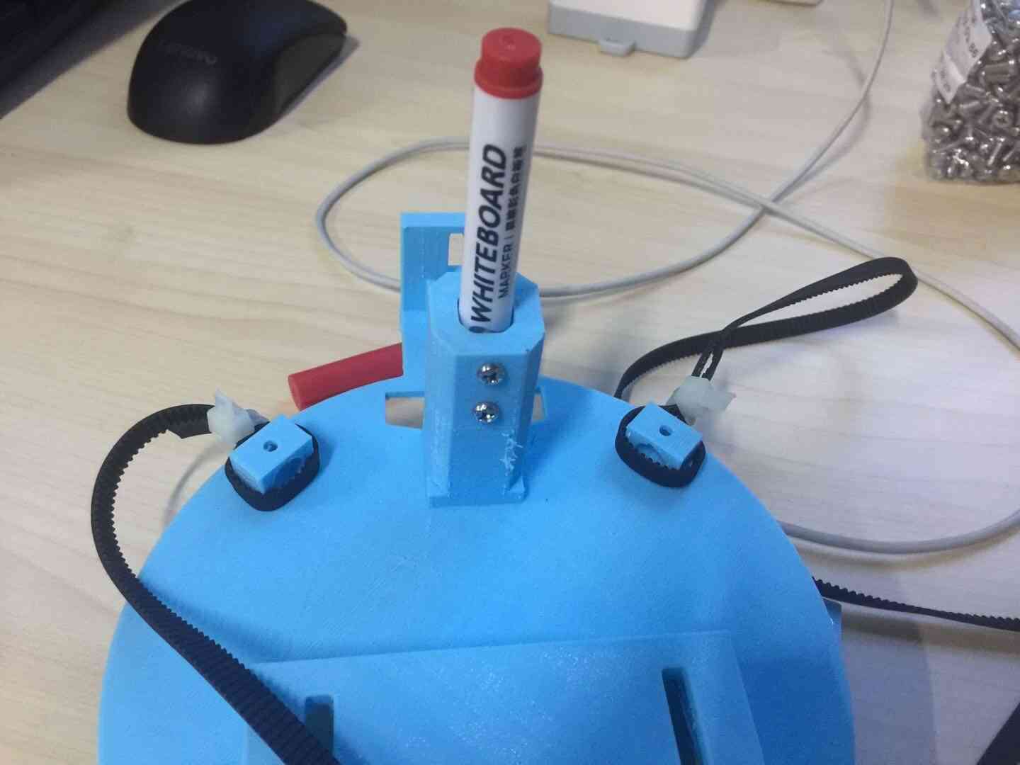
Two M4 bolts fix the connecting plate, as shown in the figure.
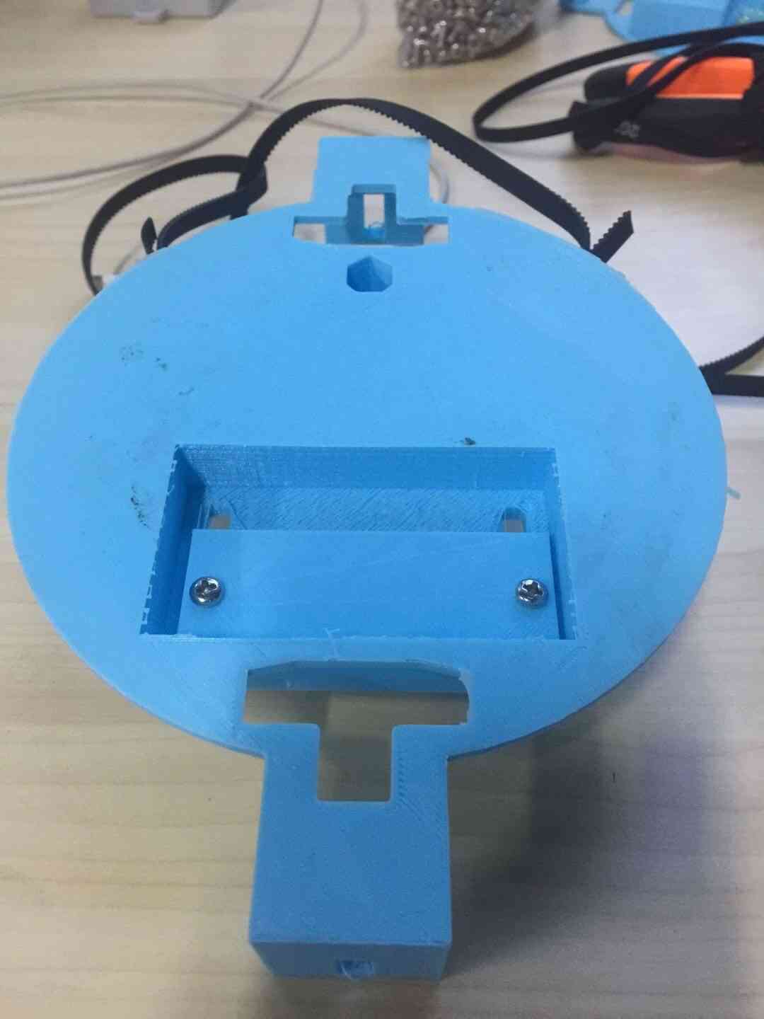
The final structure is shown below.
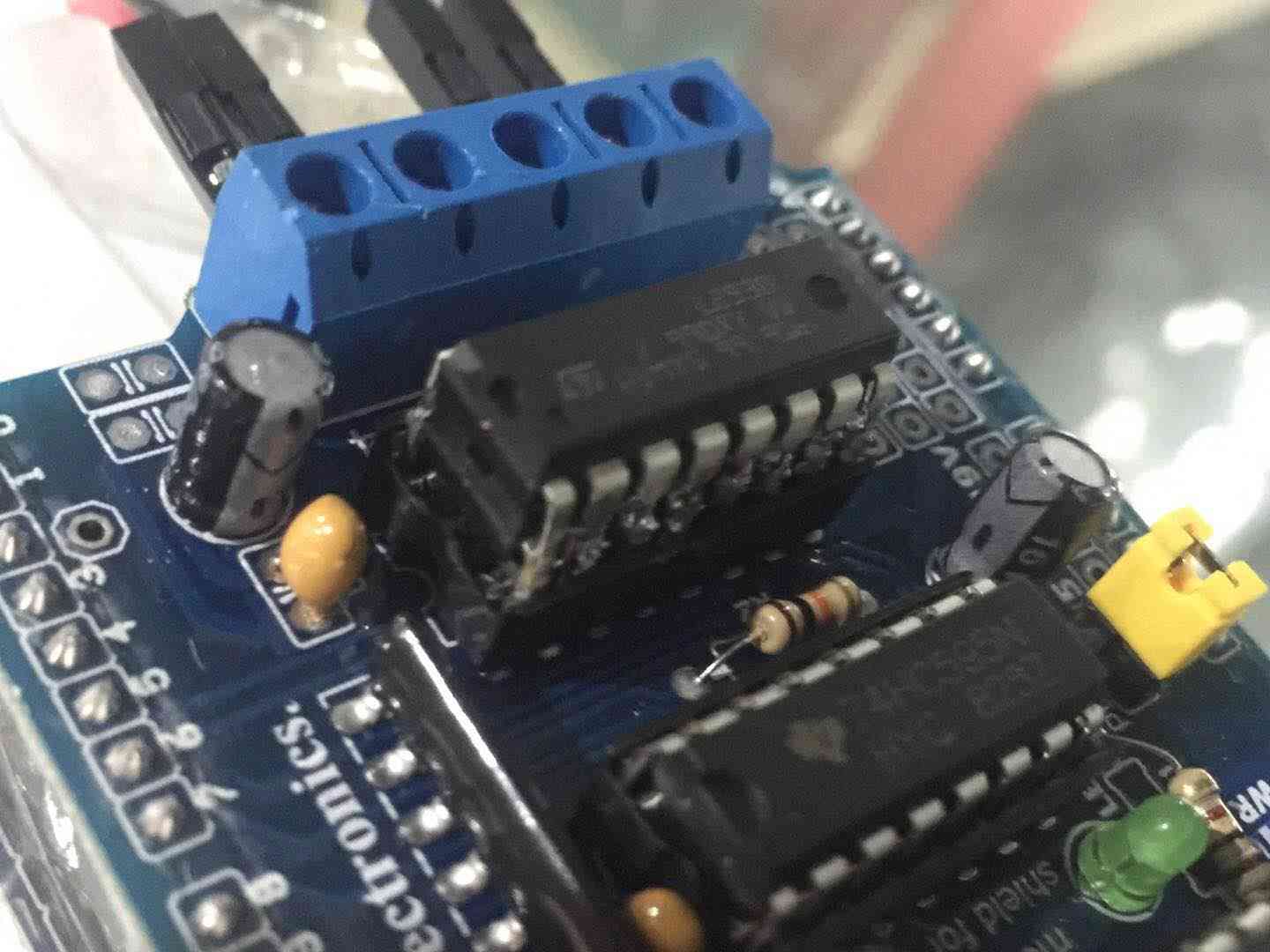
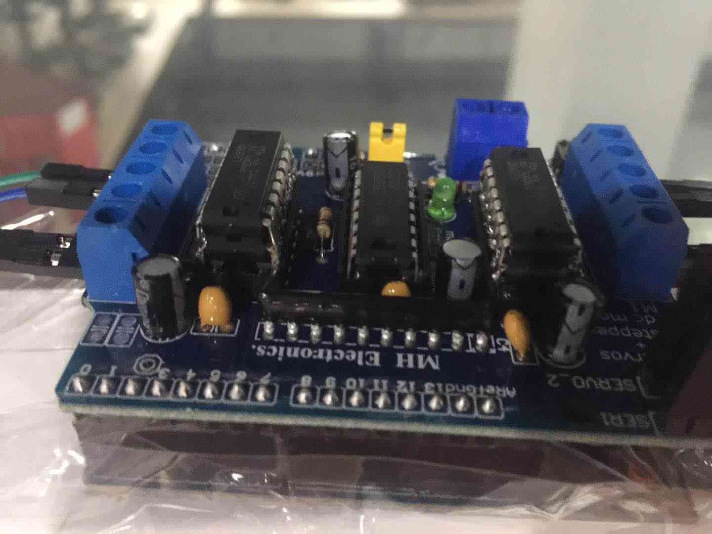
According to the reference tutorial, use the following figure for line layout. Connect the stepping motor to the motor driver shield as shown in the figure below.We set up two servos, one for the whiteboard and one for the eraser.

Since the L293D integration would overheat due to high current requirements, we welded the two L293D together.
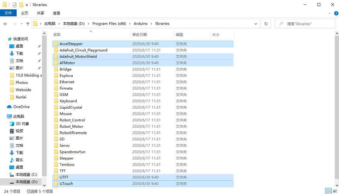
① Copy the libraries to be used for the Arduino source code. (Copy the libraries in the Polarograph libraries folder to the Arduino libraries folder.)
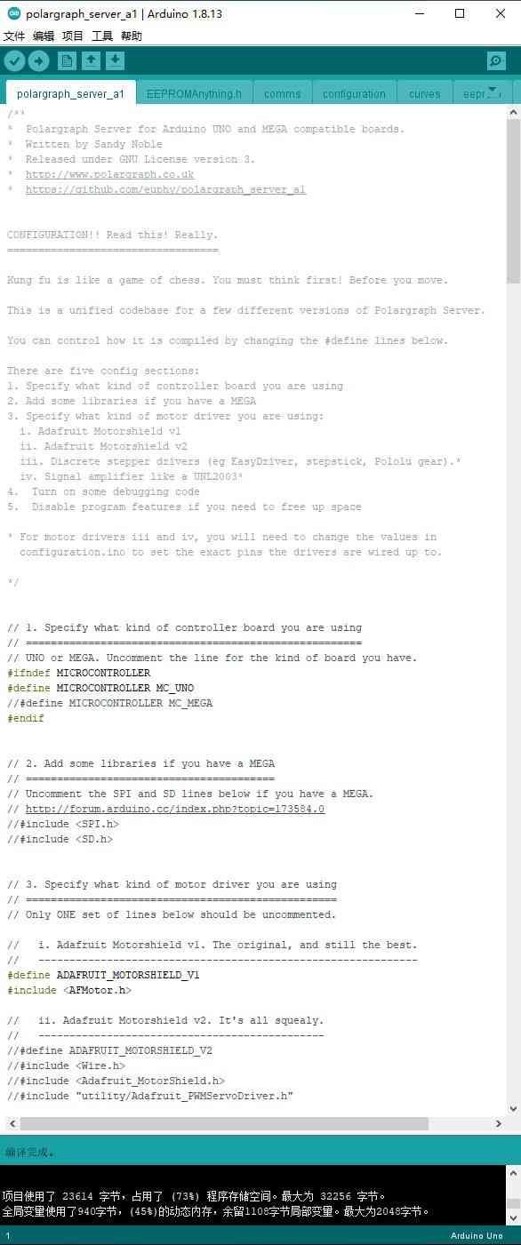
② Find the source code to use for the Arduino. (Open the course code in the Polarograph/ Arduino-source/ polargraph_server_a1 folder.)
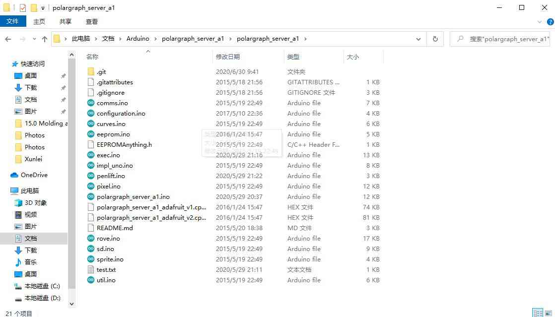
③ Upload the polargraph_server_a1.ino source code to the Arduino.
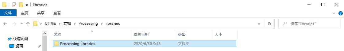
① Then open the Processing software. Find the Sketchbook folder from file / preferences/ sketchbook/ location. Find the Processing libraries in the Polarograph folder. Copy all the library folders in this folder into the libraries folder in the Processing Sketchbook folder.
② Move the Polargrapcontroller folder inside the Polarograph folder/ processing-source/ folder into the sketchbook folder.
③ Define setting
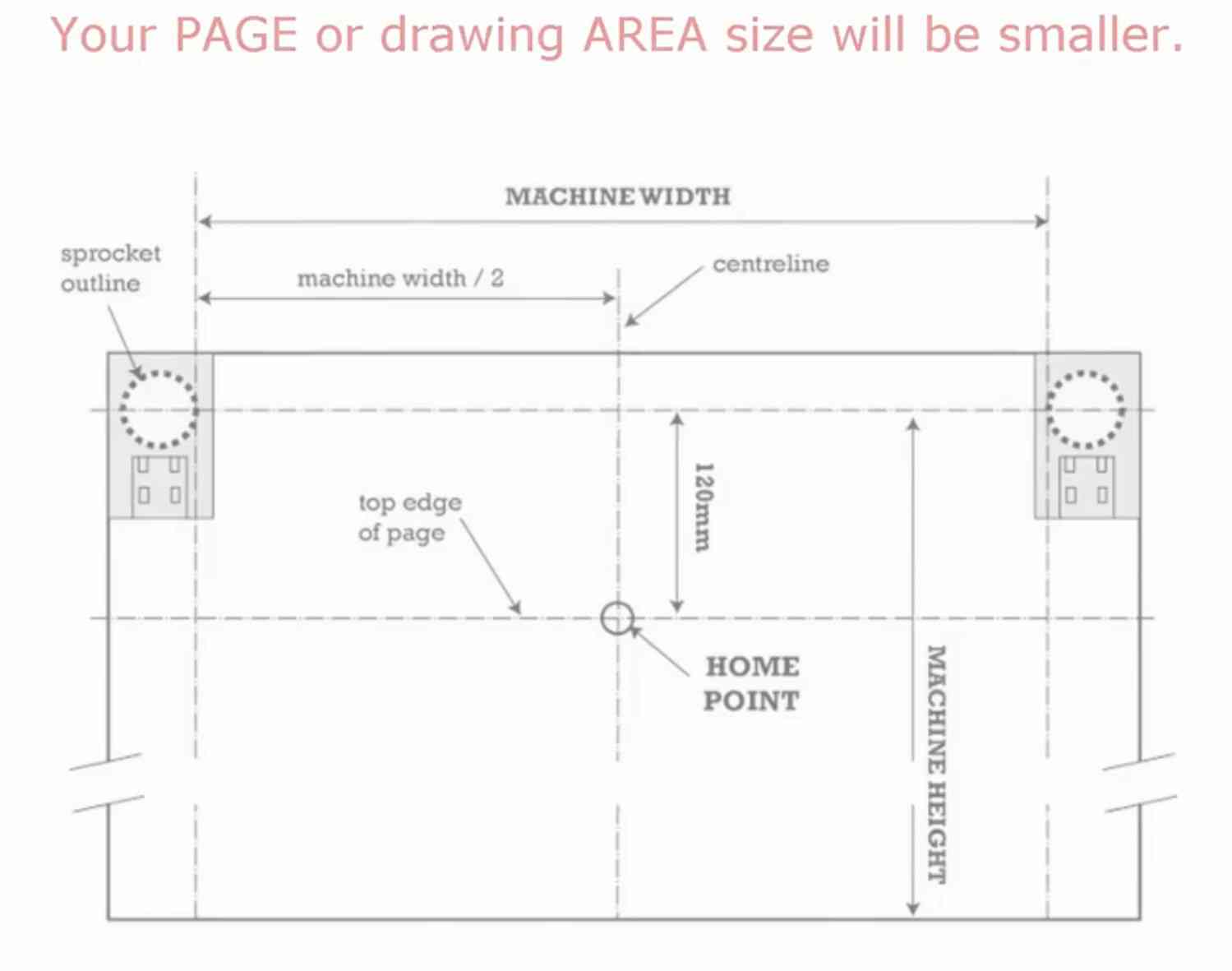
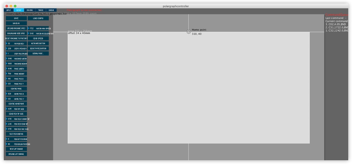
Enter the Setup section from the tool bar. Adjust the size between two pulleys on the Machine Width. Adjust the Machine Height (height between the pulley and the end of the panel. After machine dimensions, adjust the size the area you will draw. Then, first clicthe Center Page and then set the Page Pos Y value 120. Secondly click Center Home Point and set Home Pos Y value 120.
Set the MM Per Rev value according to the pulley and belt you are using. The belt is GT2 the lue is 2mm. If the pulley has 16 teeth, 2x16 = 32mm. Adjust Steps Per Rev according to the stepper motor type. The step angle of the used stepper motor is 1.8 degrees the value is 200 steps. This value is adjusted to 400 because dual motor is used.
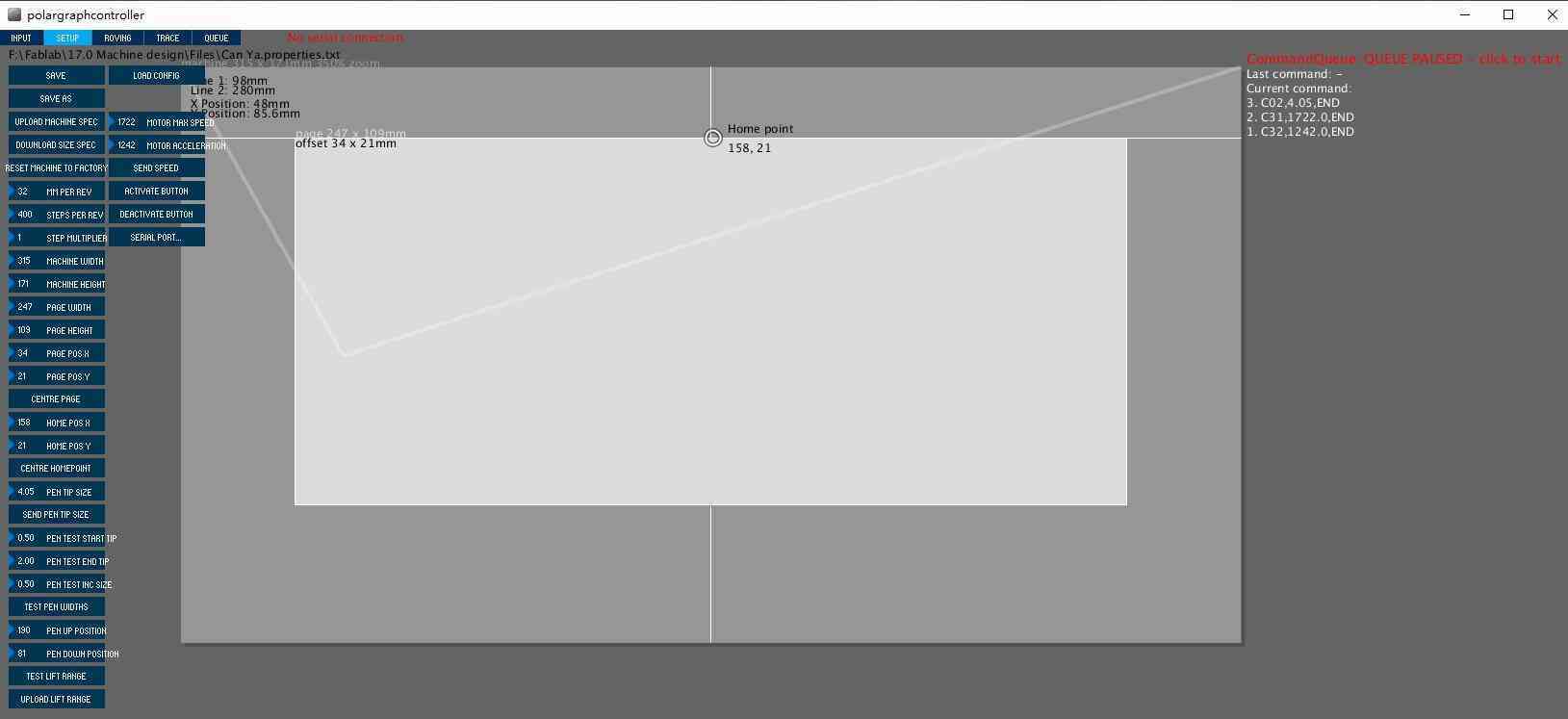
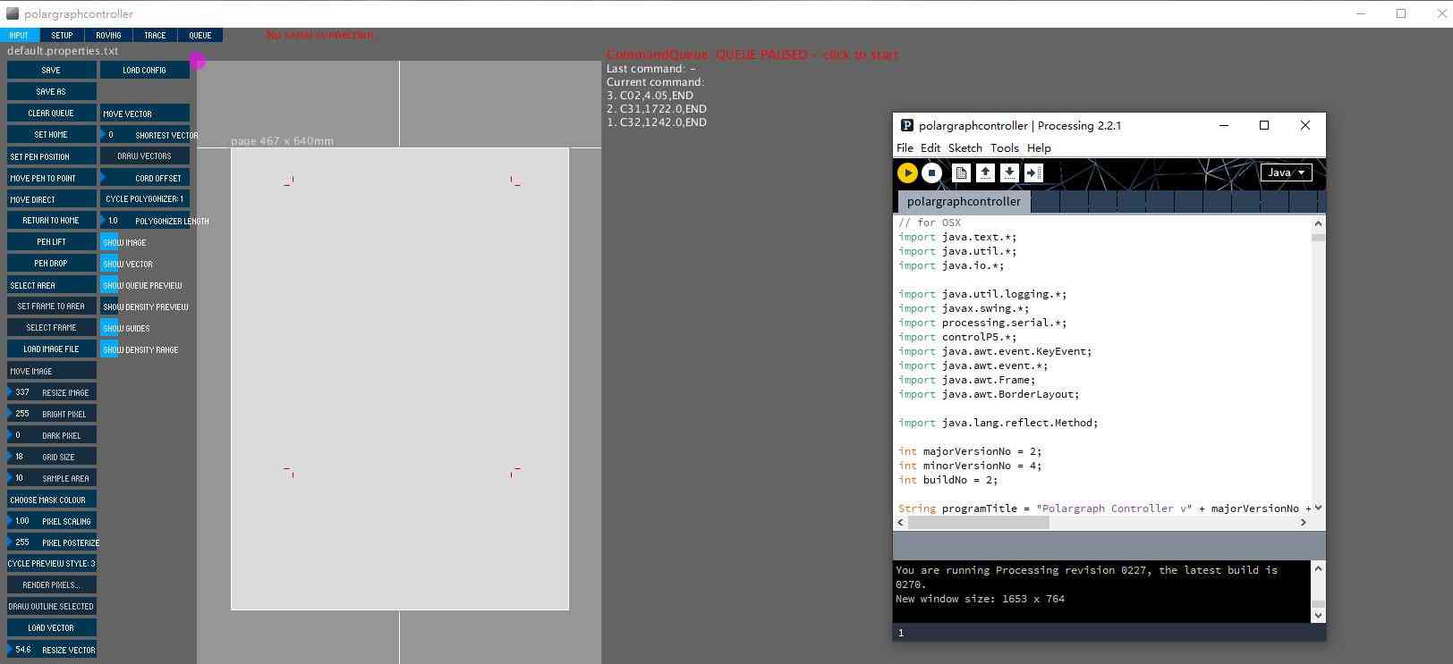
Click Serial Port and select Arduino's port from the list of connected devices. When the correct port is selected, the 'No Serial Connection' display will turn GREEN and the port number to which it is CONNECTED will be displayed. Click on 'Command Queue' and command transmission is activated. Click Upload Lift Range, then click Test Lift Range and test the servo motor angle.
Save my setting. Load the setting every time when I turn on the program. Then, Save your setting. Load your setting every time you turn on the program. Save your setting. Load your setting every time you turn on the program. Save your setting. Load your setting every time you turn on the program. Save your setting. Load your setting every time you turn on the program.
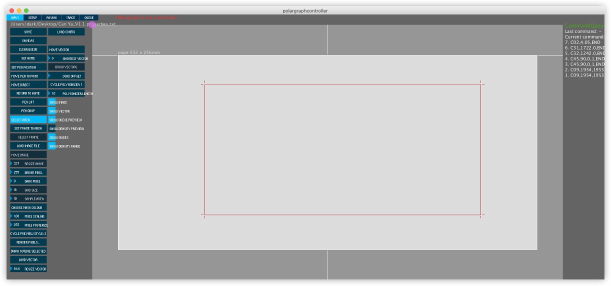
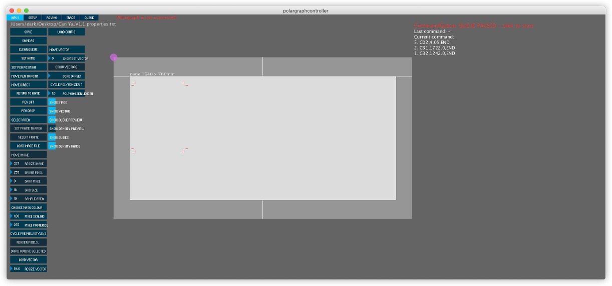
Then, I draw a circle in software of Inkscape and convert image to the SVG format. Adjust image size with Resize Vector. Move the image to the desired area with Move Vector. Then adjust the area to be printed with Select Area and Set Frame to Area. Finally, click the Draw Vector command to start the machine.
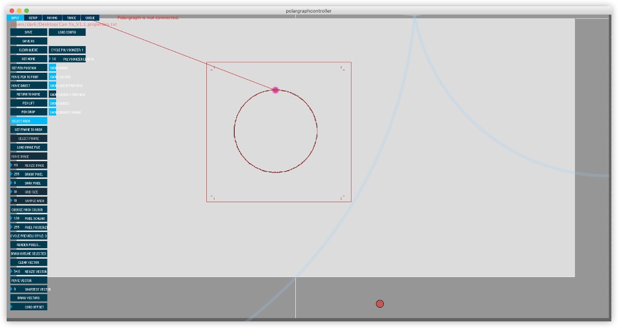
The pen drawing a circle.