week_11
Output Devices
Propose a final project masterpiece that integrates the range of units covered, answering:
At first, I used the Arudino UNO to control the stepping motor to practice the output drivers. Connection line as shown:
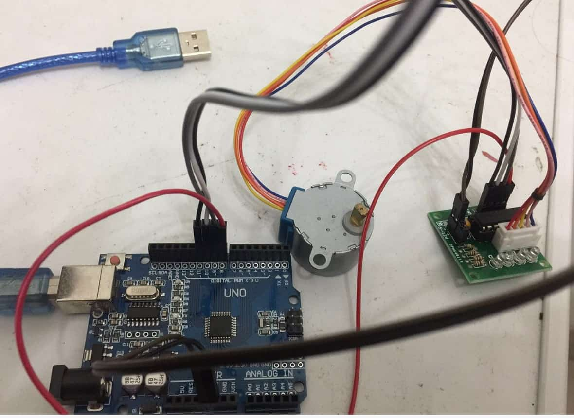
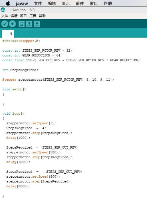
The pin 8 in UNO board connection the IN1 in ULN2003, the pin 9 in UNO board connection the IN2 ULN2003, the pin 10 in UNO board connection the IN3 ULN2003, the pin 11 in UNO board connection the IN4 ULN2003. Then I programed in the Ardino.
Power Supplying to the circuit is 5V.
By using an oscilloscope, I got my speaker running at around 3.87V.
By using a multimeter, I got my speaker funning at around 0.13mA.
P = UI = 3.87*0.13 =0.5031 watts
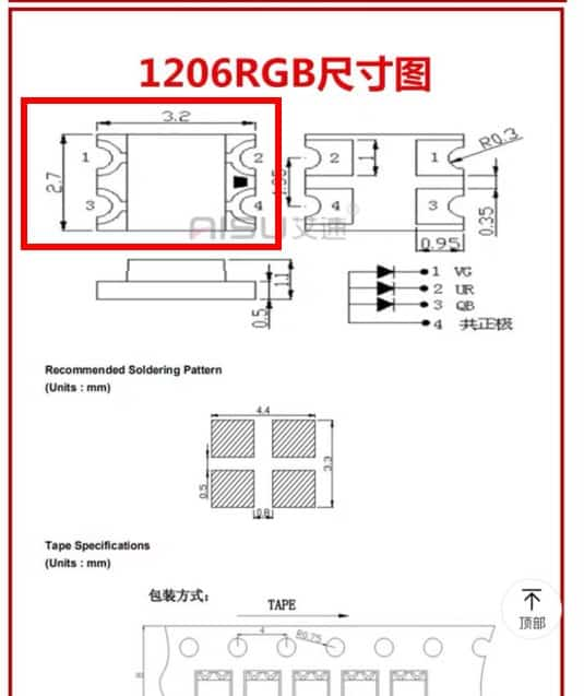
This week is exploring output devices. So, this week the first I decided to put an RGB LED output devices. RGB means red, blue and green LEDs. RGB LED products combine these three colors to produce numbers of hues of lights.
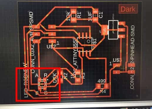
To create the schematics, I needed the list of components that I needed for the board. Once I secured the components needed, I could easily choose the correct component from the fab.lib in Eagle to create the schematic. The components I needed were:
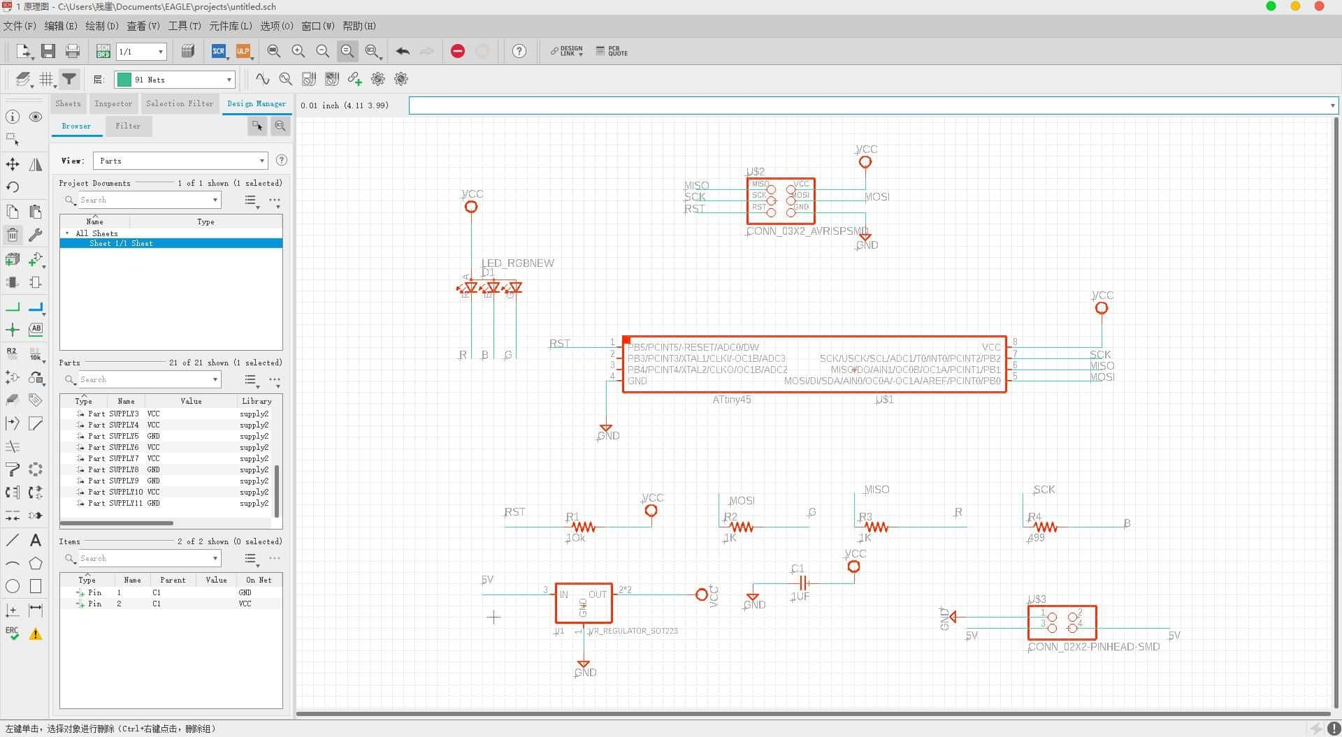
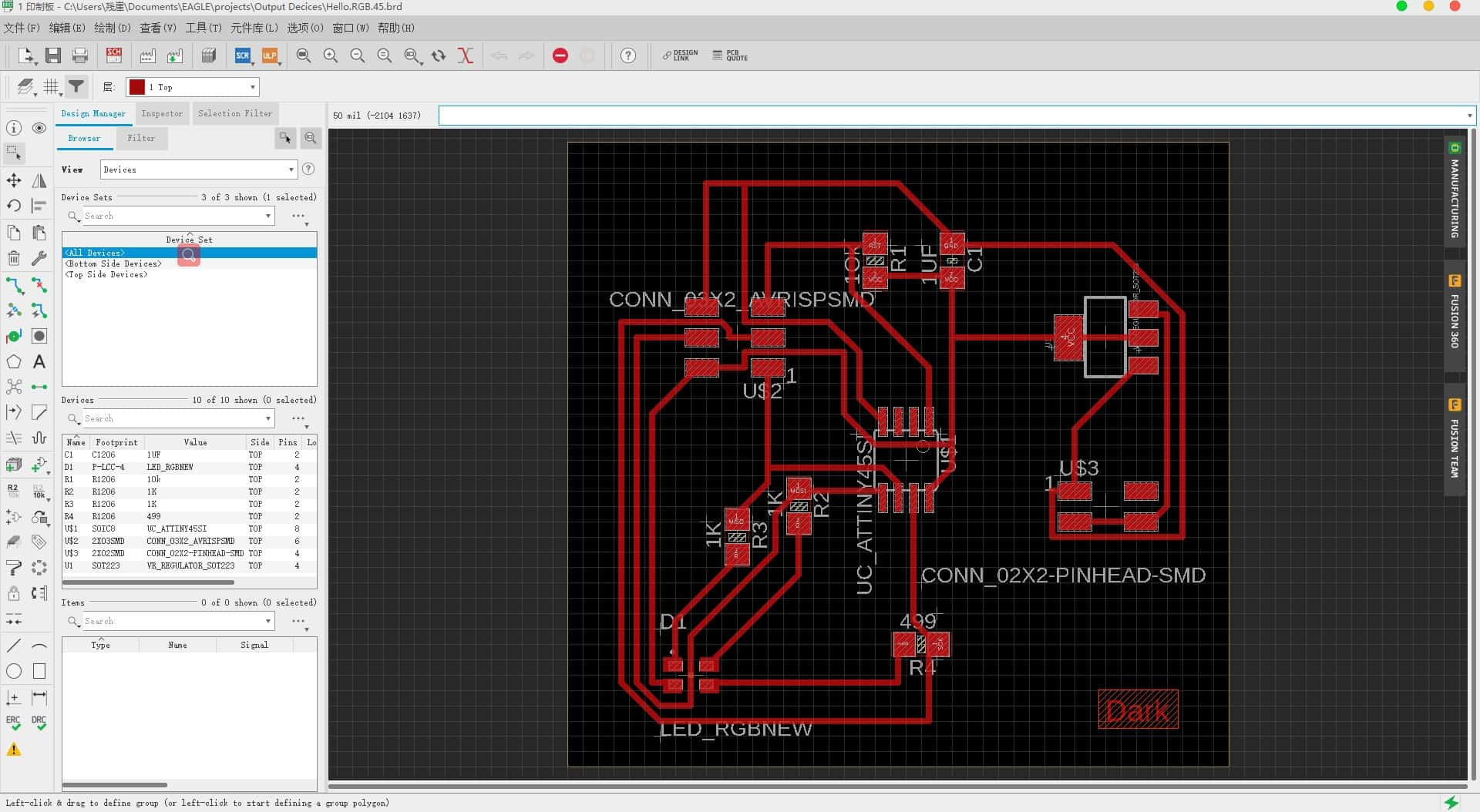
Then I proceeded to convert the schematic to a board file. So, the next phase was to place all the above-mentioned components on the board. I moved over to board view and started dragging the components over and placing them. The RGB Led board is fairly straightforward in its layout. It was a simple task to drag it over.
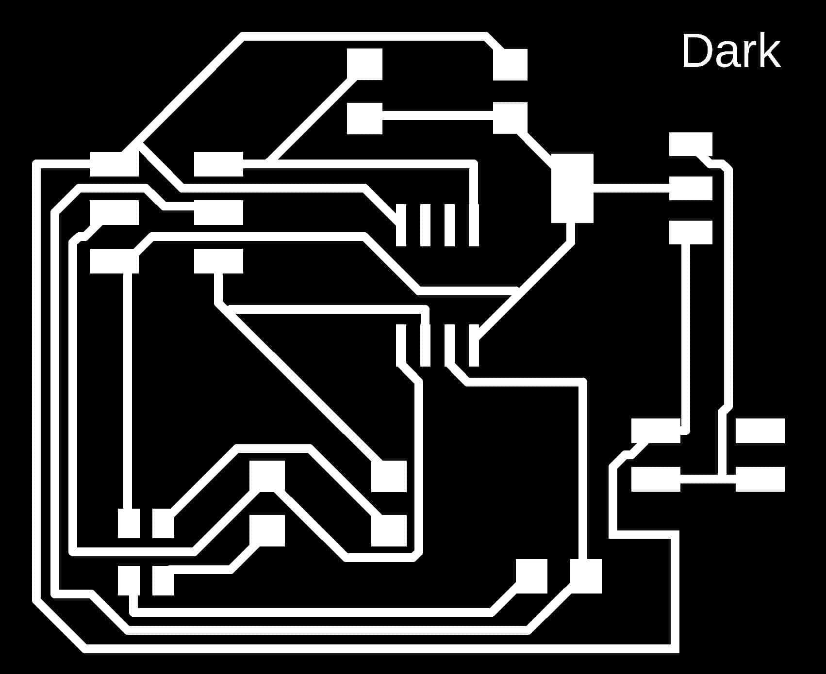
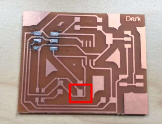
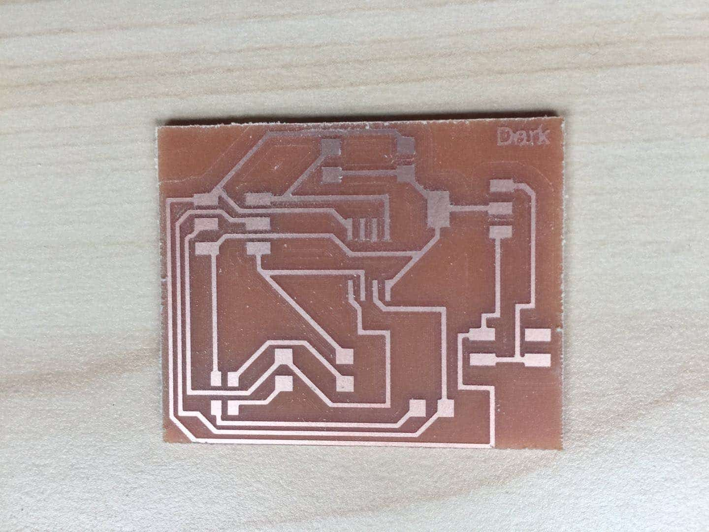
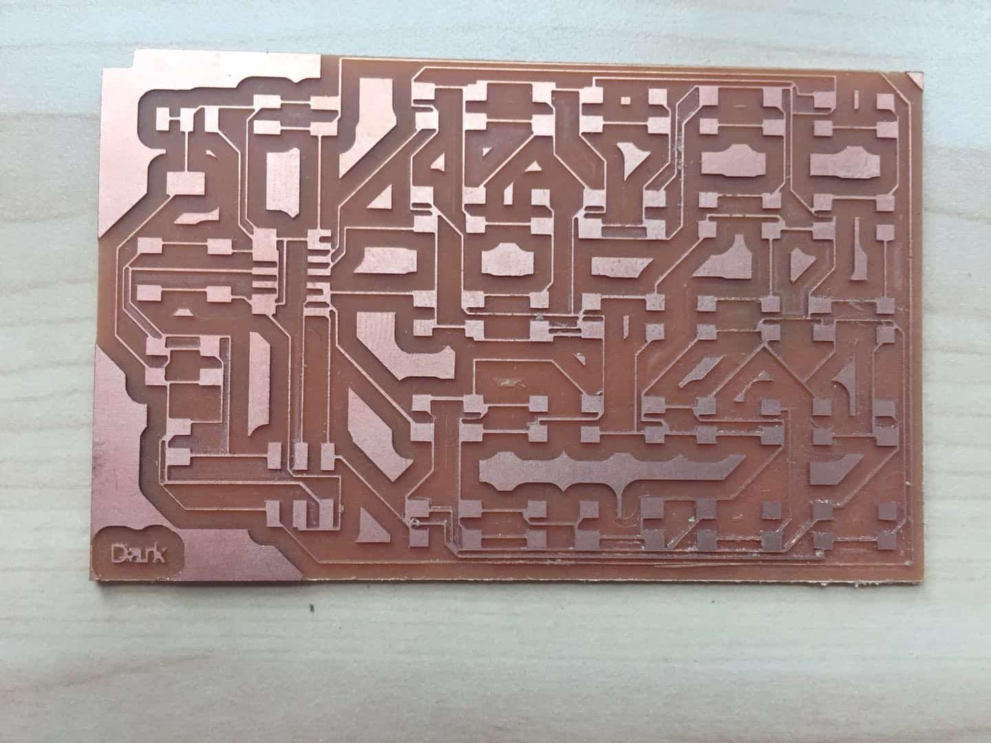
This week I did some small mistake, so it took me a lot of times. The first time I laid out the plates and processed them, I found that some parts were not cut in place.
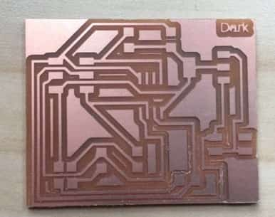
After that, line correction was carried out through GIMP, as shown in the following figure.
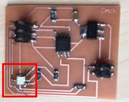
When welding to the RGB lamp, I found that the order of the RGB pins I purchased was different from that in the fablab module, which was rotated 90 degrees clockwise. RGB LED VCC pin in my board is pin A. But the RGB LED has the wrong aspect ratio
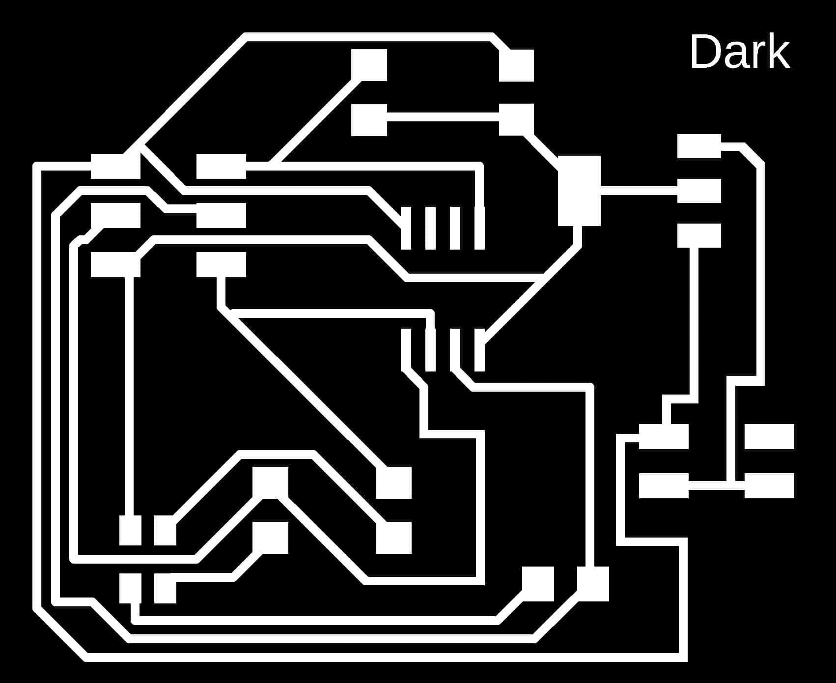
I used GIMP to modify my PCB board. I increased the area of the RGB part.
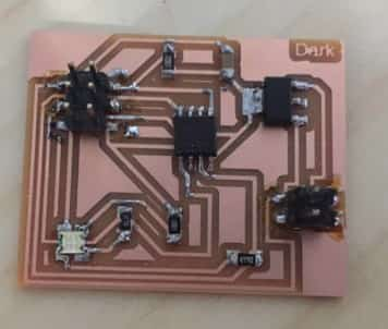
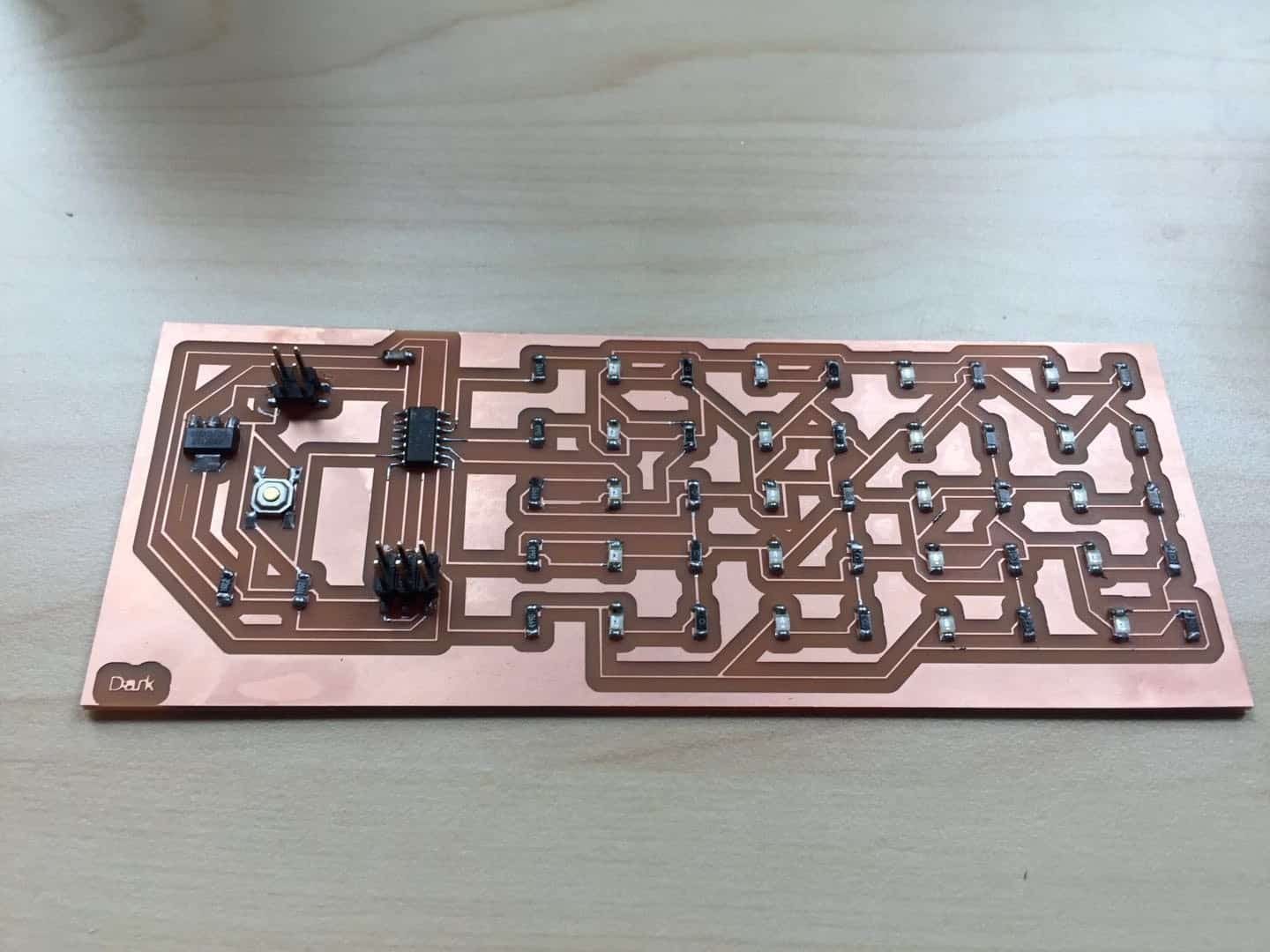
Then I soldered the necessary components on my board.
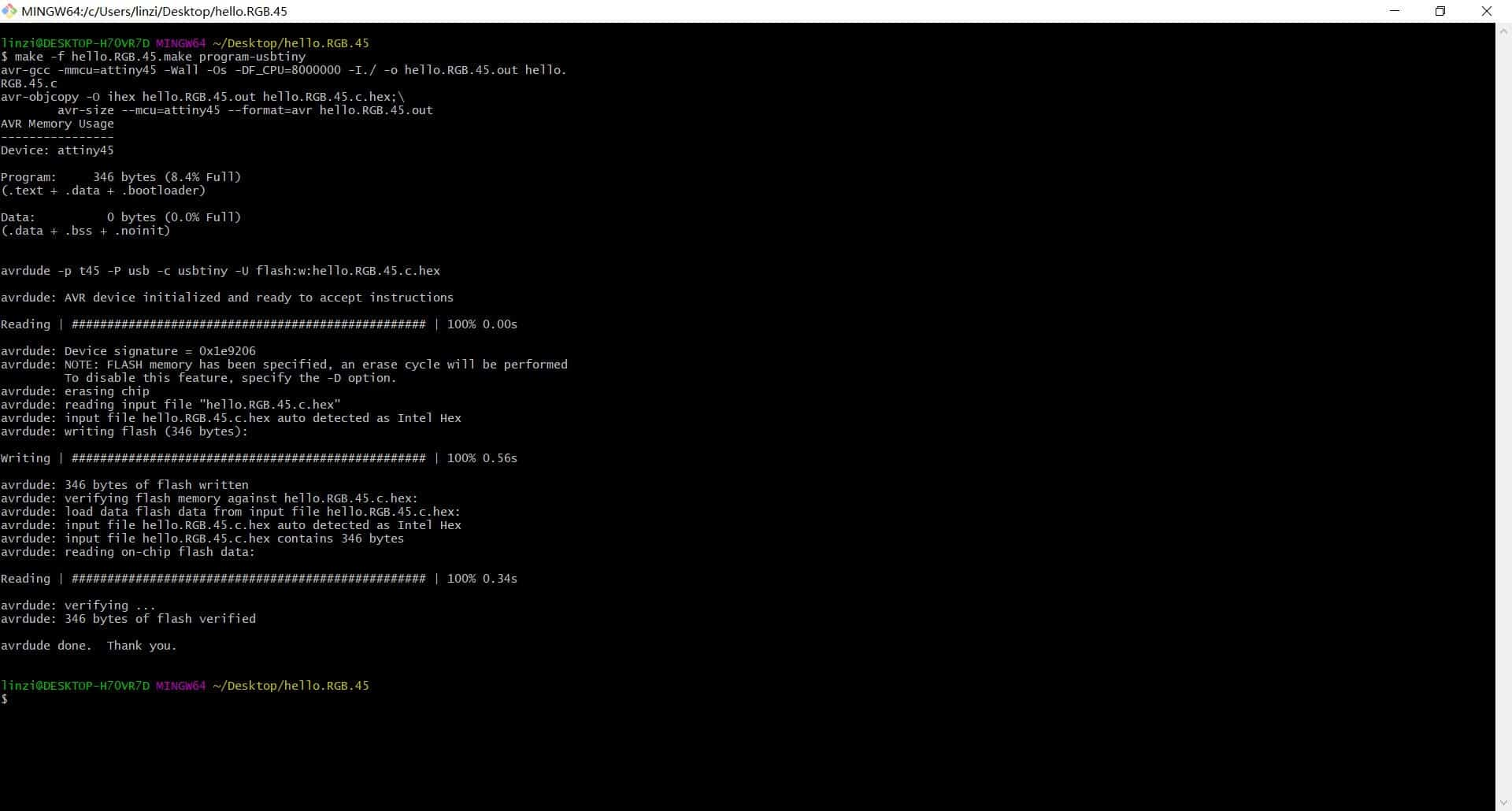
I used the USBtiny board to program my board and I used the Arudino UNO to provide the power of 5V. I used Neil's c code and made file to program the board and saved them in a specific directory inside the Desktop. I opened Git Bash and went inside the directory where the c code and the make file where located. Then, I ran the following commands:
make -f hello.RGB.45. make program-usbatiny
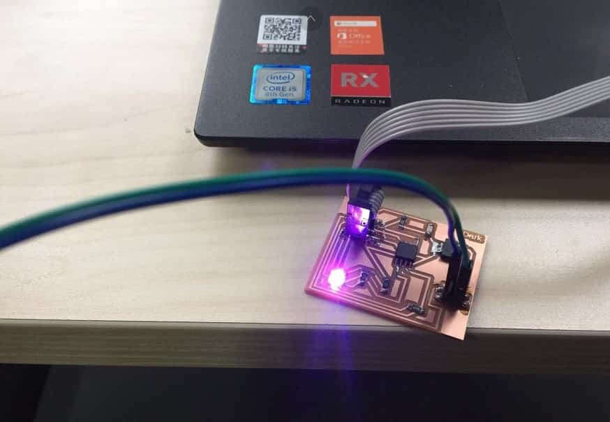
Everything went well. Work done! Here's my final video:
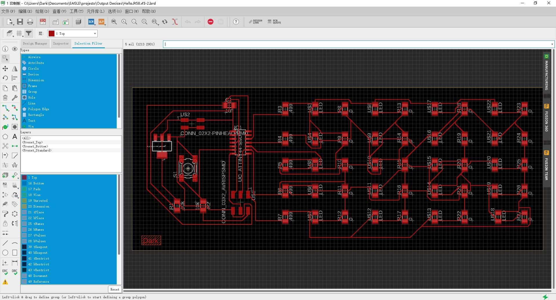
I redesigned Neil's LED Array Board in the Eagle PCB Software and I added a button so that the user can switch can change the characteristics of the LED cycle by clicking. I also tried to do an LED array which would cover a larger surface than that of a PCB board. Here is the list l need for my board.
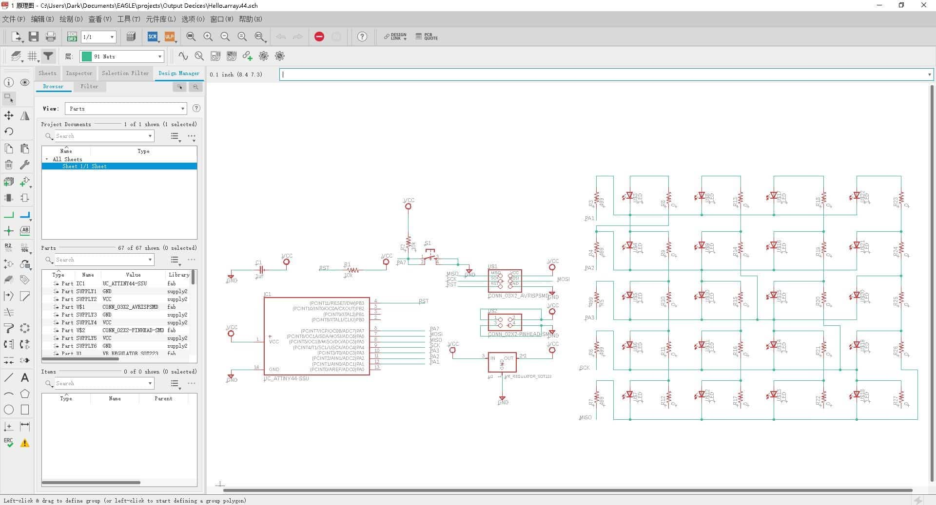
After specifying the new connections in the schematic, the new components appeared in the board view of Eagle. Here I was able to route the button and its resistors and make the traces of my board. I exported the traces in monochrome. pang with a resolution of 1000dpi after turning off the unnecessary layers and keeping only the traces. I did something wrong with the tolerances in the Design Rule Check because it did not give me any errors although as I realized after cutting the board there was not enough space between some of the traces.
Routing the board was a little challenging in the beginning but went very smoothly after I moved the LED rows and the rest of the components in their proper positions.
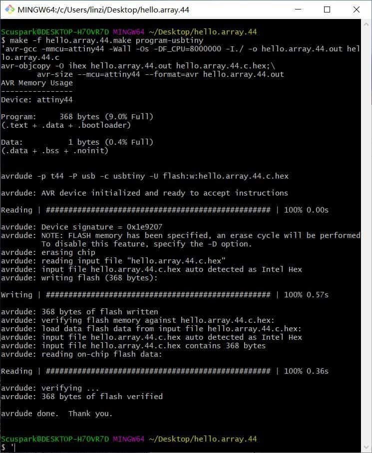
Then I downloaded the "hello. array.45.C" and their respective "hello. array.45. make", to program the board. I used the USBtiny to program the Led Array board" on windows 10 system. First, the “makelife” file is used and this prompts the file to generate another file called hello.array.44.hex which is used to program the ATtiny44 with the following command:
- sudo make -f hello.array.44.make program- usbtiny
Everything went well. Work done! Here's my final video: