week_09
Input Devices
This week we’re exploring input devices, i.e. how our microcontroller boards can start sensing the physical world. For my final project I need sensor for monitoring the illuminance of the smart socket. so, I decided to make one this week. So, the first I decided to put HC-SR04 ultrasonic sensor. Through Eagle I designed both plates, both with the Attiny45.
An input device is any hardware device that sends data to a computer, allowing you to interact with and control it.
(1) Light Sensors: Light Dependent Resistor
Analog sensors that are used for detecting the amount of light striking the sensors are called as light sensors. These analog light sensors are again classified into various types such as photo-resistor, Cadmium Sulfide (CdS), and, photocell. Light dependent resistor (LDR) can be used as analog light sensor which can be used to switch on and off loads automatically based on the day light incident on the LDR. The resistance of the LDR increases with decrease in light and decreases with increase in light.
(2) HC-SR04 Sensor Features
Ultrasonic sensor is also known as Sonar sensor. Basically, Ultrasonic sensor is a device which is used to measure distance to an object. This works by sending out a wave which comes back by striking an object, it measures the time elapsed from generating of the wave to bounce back. This way it measures distance from the origin position of the sensor to the object. It follows the given below formula to calculate the distance.
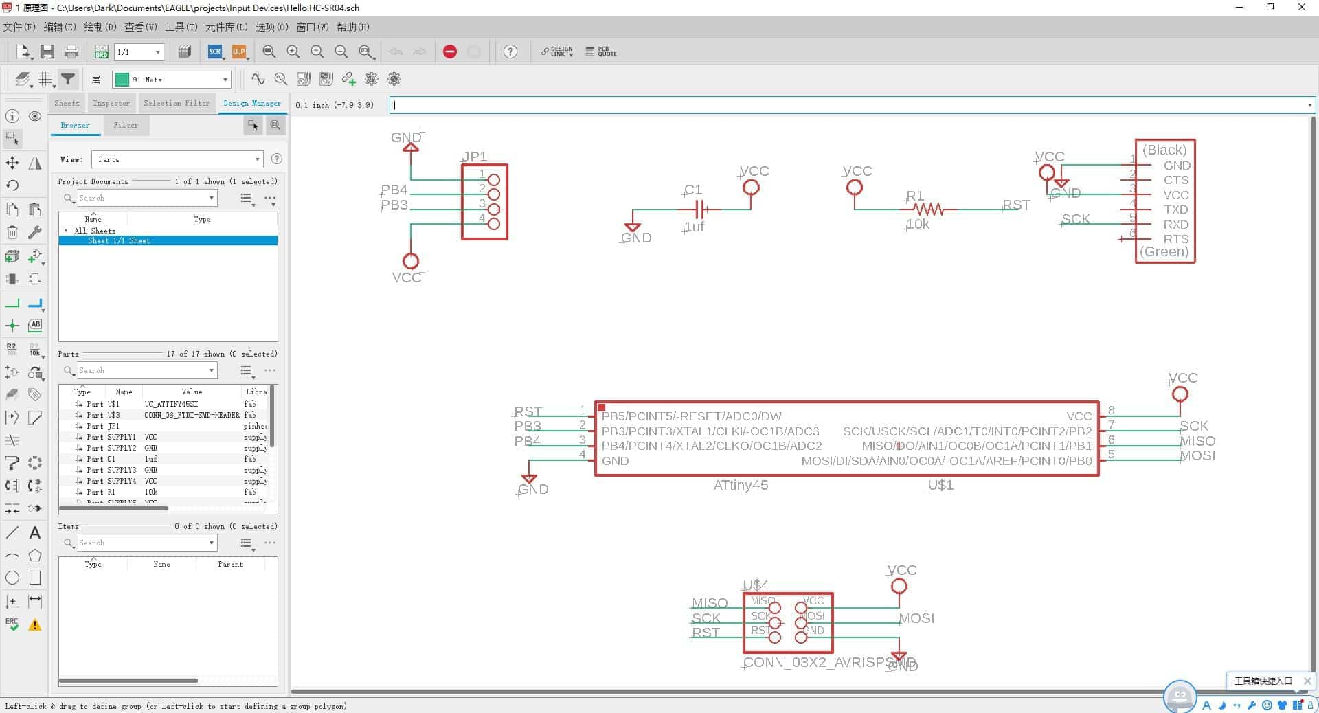
⑴ Eagl
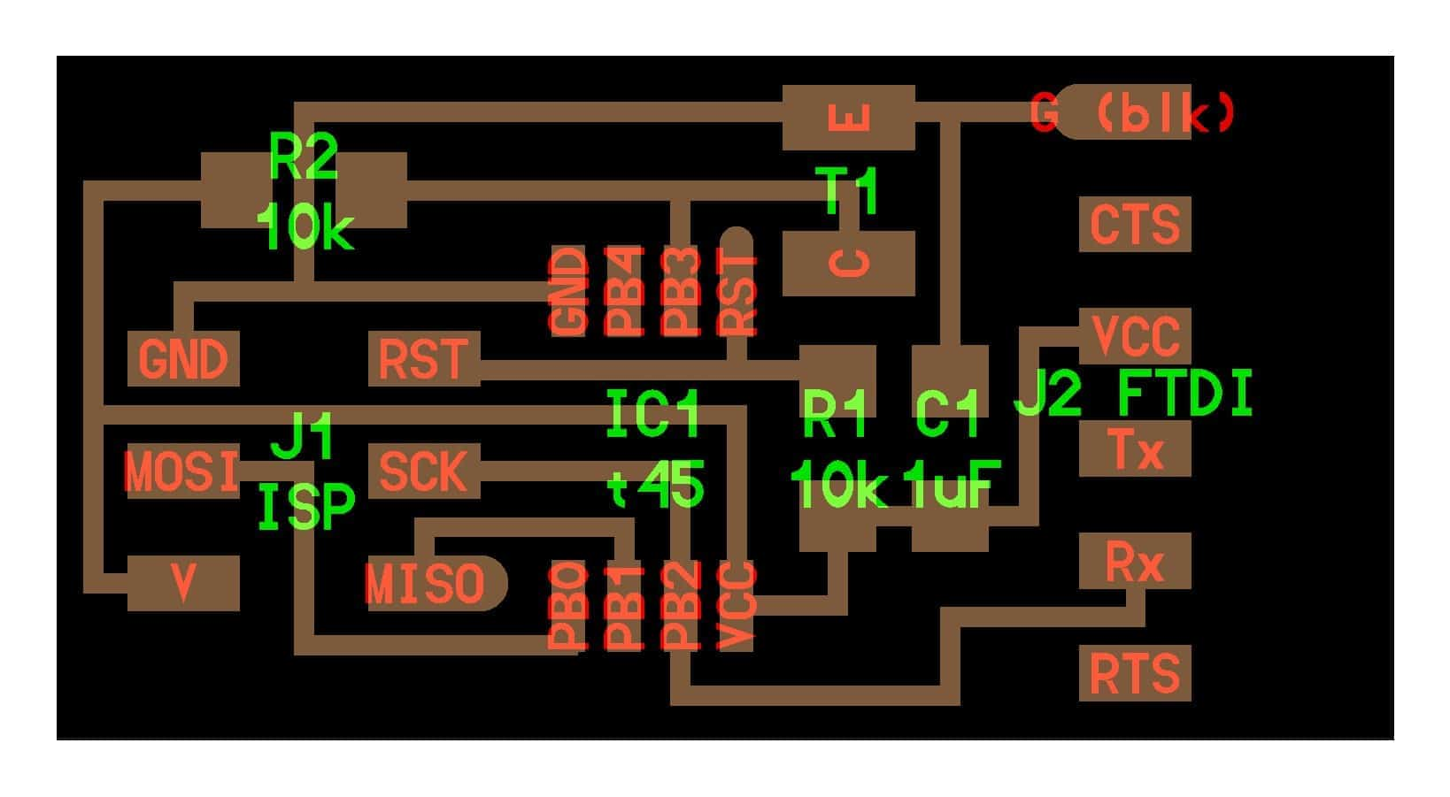
I used eagle to start getting my board designed. The first thing I did was create a new project named “Input Devices”. I decided to make it just with the components that Neil did without adding extra (using ATtiny45). I used Eagle to redesign the same ultrasonic sensor. The necessary components for producing the board are the following:
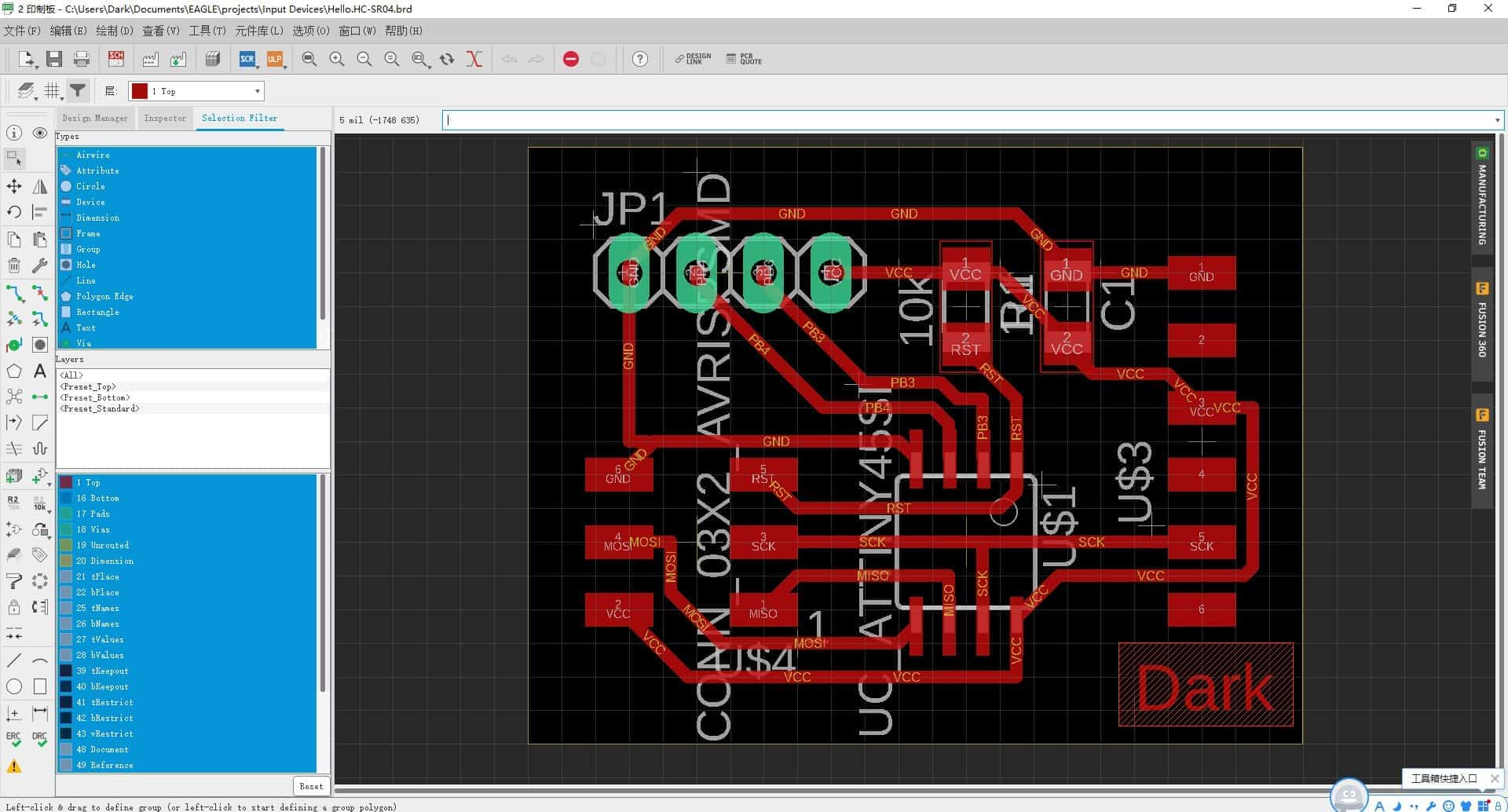
⑵ PCB Production
I used the Roland SRM-20 milling machine, controlled with mods to mill the board, following the same process as in Electronics Design week.
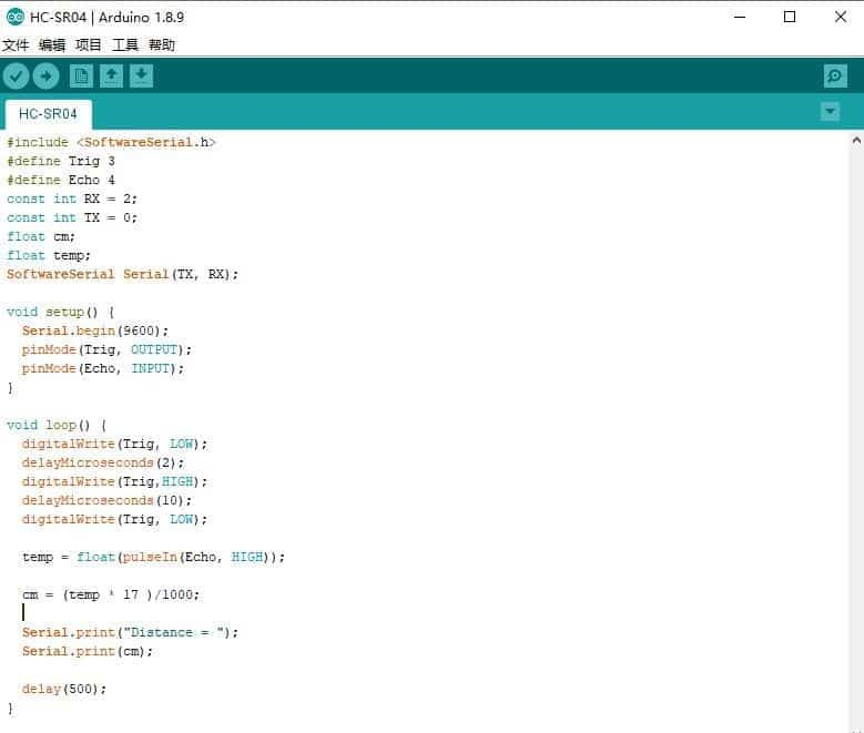
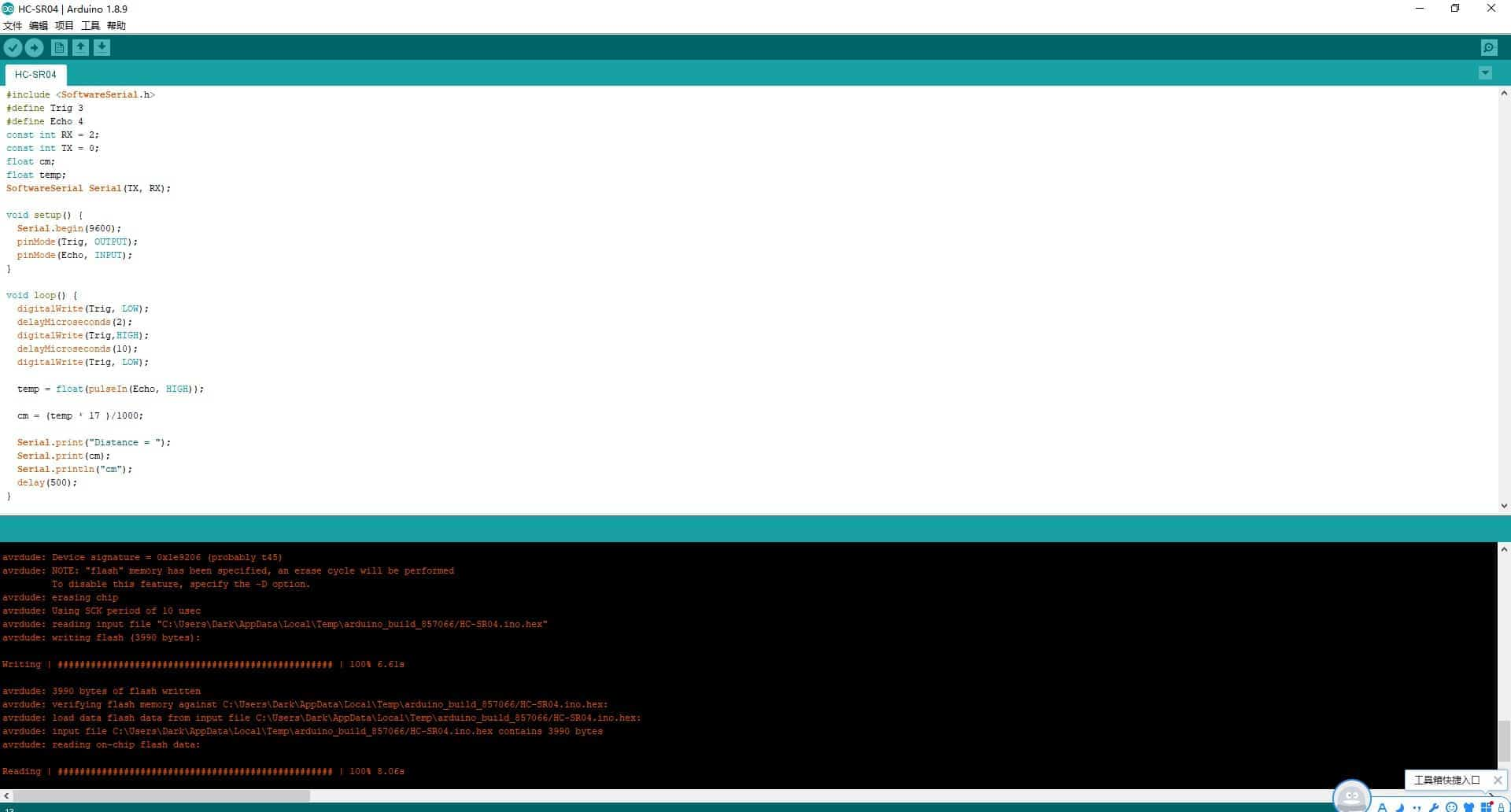
(3) Programing
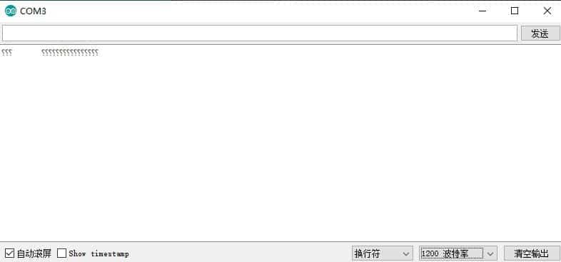
I encountered a lot of problem with synchronization on the ATtiny when programmed with the Arduino UNO and Arduino IDE. There is a problem I had which is it only showed “?????” on the serial monito. The conditions are the baud rate was 9600, programming at 1Mhz or 8MHz. Then I set the baud rate was 19200, 4800, 2400,1200, 38400. I didn't know why. I think it might have something to do with the clock.
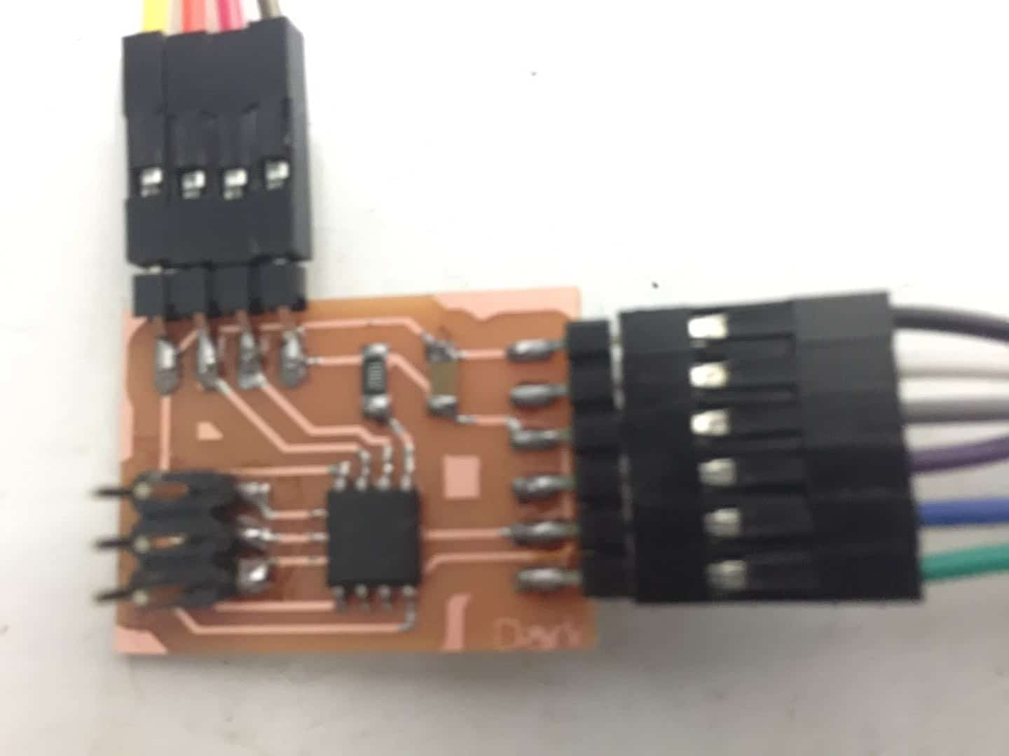
Then I made another board of HC-SR04 and programing in the same way. It worked.
⑷ Testing
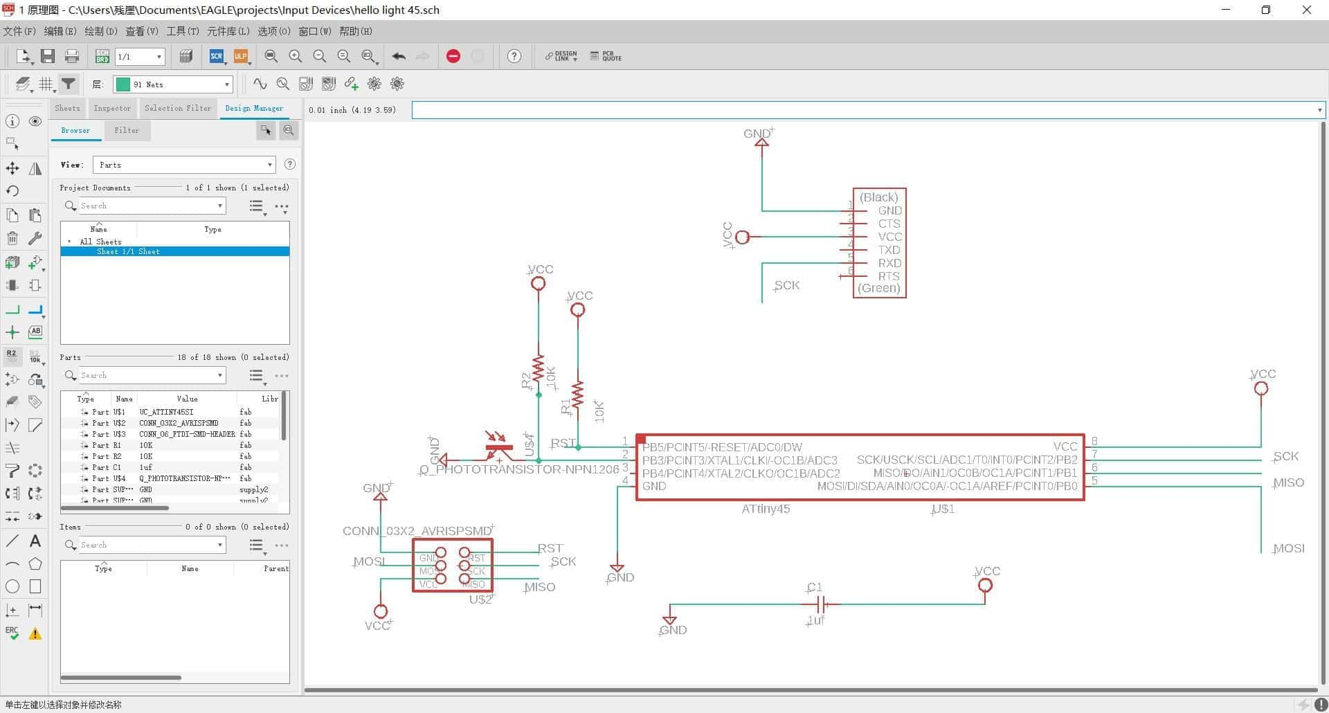
(1) Eagle
I used Neil's design for the temperature sensor board "hello.temp.45". The board is shown below:
The necessary components for producing the board are the following:
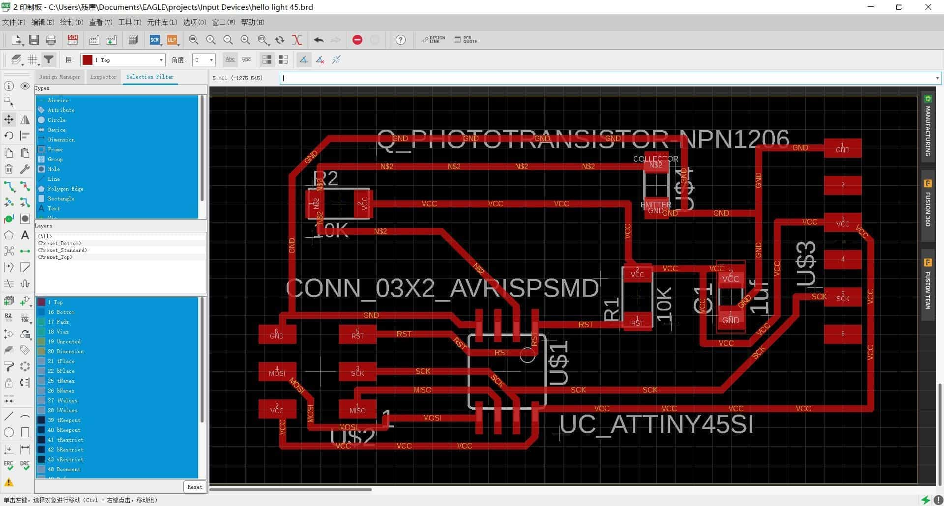
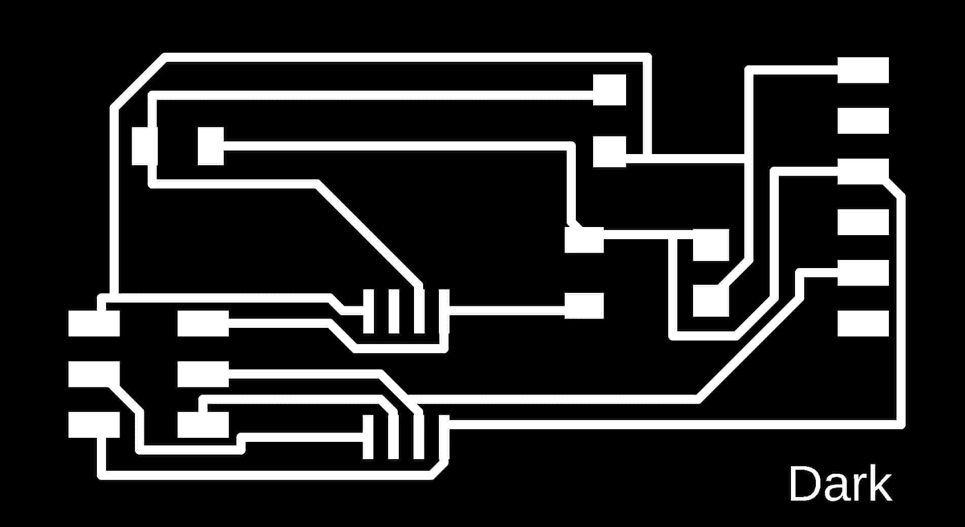
Then I export the images from Eagle with 1500 resolution.
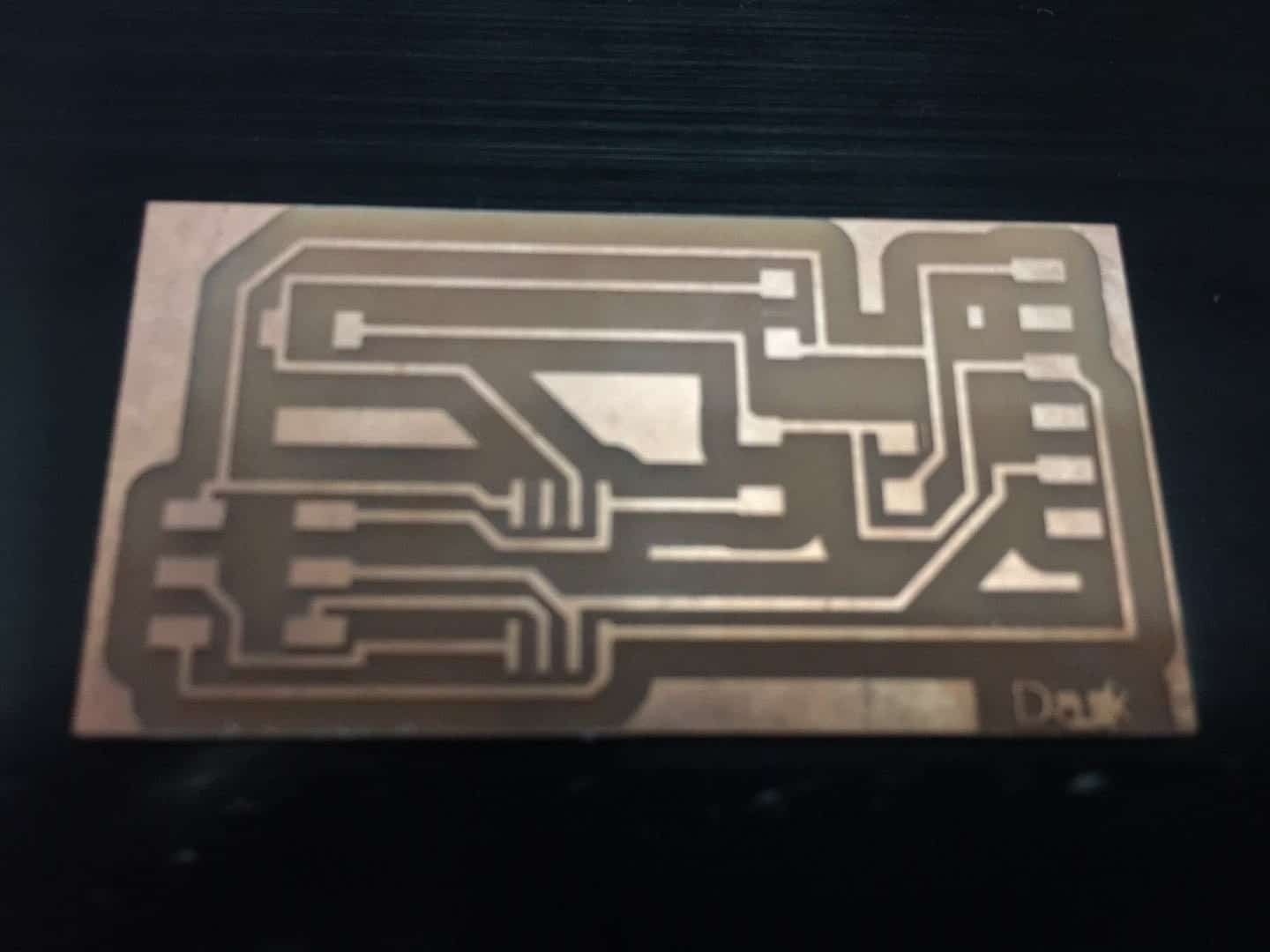
(2) Fabricate my board
I usually used one offset to make sure of all traces will mills.
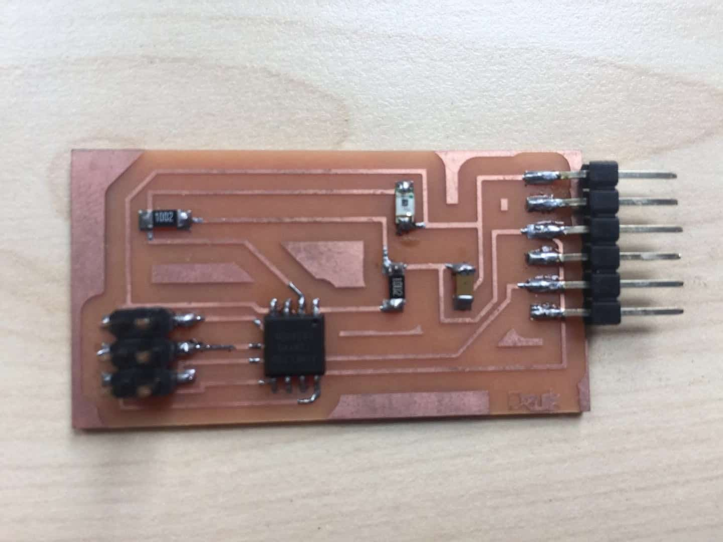
Weld and Programming the microcontroller ‘ATtiny 45’.
⑶ Programming
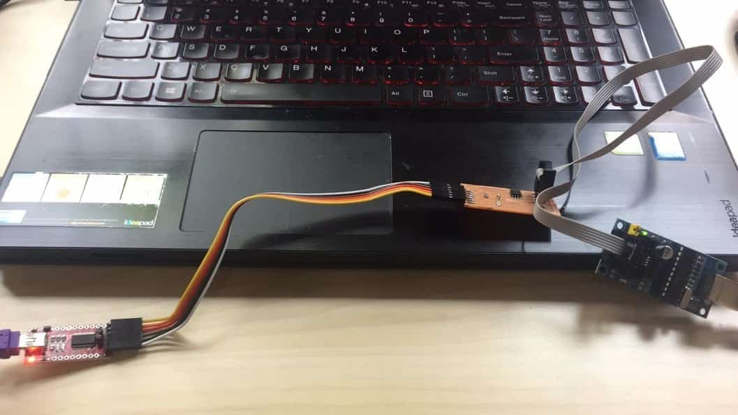
For this step we need to program the sensor PCB, Actually I used the Neil’s Code without any changes. I used the USBtiny board to program my board. I used an FTDI cable (5V) to connect my board with my computer and an ISP cable to connect the board with the USBtiny programmer. Then I used the make file that Neil shared in the lecture.
Then, we open command prompt in the directory that we downloaded the files in, and Write
make -f hello. light.45. make program-USBtiny
1) - f to select the file that we need to maker
2) hello. light.45. make … we have to write the exactly name file without any changes
3) program-USBtiny … the exactly function we need to do
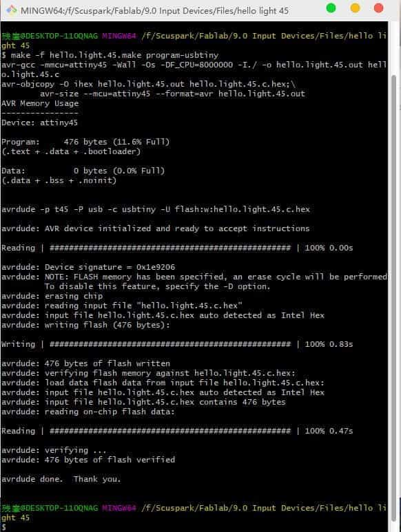
Then, I need to write this line
avrdude -p t45 -P usb -c USBtiny -U flash: w: hello.light.45.c.hex
1) -p to specify the type of avrdude ‘t45’, attiny45
2) -p to specify the connection port … usb
3) -c to select the programmer ‘usbtiny’
4)-U to specify the memory operation

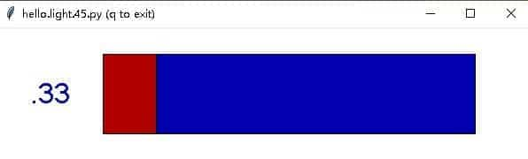
⑷ Testing
This step I also used the Neil’s Code without any changes. Then I need to write this line:
python hello.light.45.py COM3
But there are some mistakes.
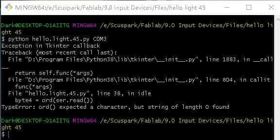
Therefore, I performed serial port reading and programming in arduino by myself. The program is as follows.
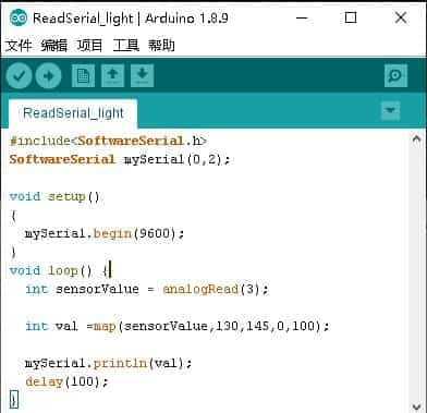
Then I test it and it worked.
I used a universal digital meter to measure the voltage of the photosensitive resistance and found that the voltage decreases as the illumination increases.