week_08
Embeded Programming
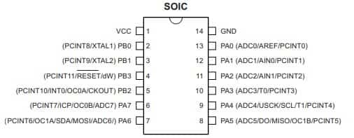
I have downloaded 8-bit AVR Microcontroller with 2/4/8K Bytes In-System Programmable Flash manual for ATtiny 24, 44 and 84 in this Website.
From this Data-sheet I have understood better how ATtiny44 pins are configured, what can I connect to each type of pin, and that there is a lot of technical information for my next exercises where I am going to use this Micro-controller.
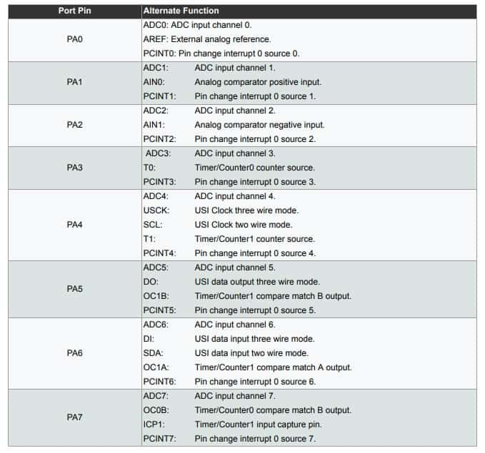
But for my final project, I will need a stronger micro-processor. So I researched a microcontroller, in this case the ATmega32U4 Which the microcontroller, you can download the datasheet in this Website. It was 438pages long. So, I have picked out some of the research that I think is important.
⑴ Overview
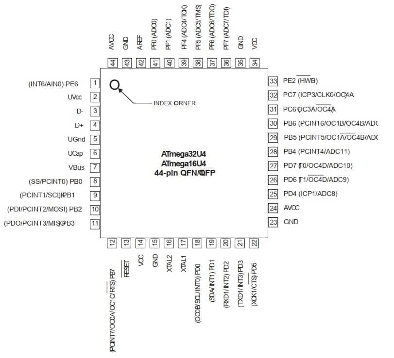
At a certain point, I realized I was quickly going to have more screen captures than I knew what to do with because of just how much information is in the data sheet. But I can't read it all, so is there anything I don't understand about microcontrollers that I need to check the datasheet. And also, I'll read it part by part, to be prepared for the day of making my own Final Project PCB with it.
As I am more familiar with Arduino programming language, so I began with it. The Arduino Integrated Development Environment (IDE) is a cross-platform application (for Windows, macOS, Linux) that is written in functions from C and C++. It is used to write and upload programs to Arduino compatible boards, but also, with the help of 3rd party cores, other vendor development boards.
The Arduino IDE supplies a software library from the Wiring project, which provides many common input and output procedures. User-written code only requires two basic functions, for starting the sketch and the main program loop, that are compiled and linked with a program stub main () into an executable cyclic executive program with the GNU toolchain, also included with the IDE distribution. The Arduino IDE employs the program avrdude to convert the executable code into a text file in hexadecimal encoding that is loaded into the Arduino board by a loader program in the board's firmware. By default, avrdude is used as the uploading tool to flash the user code onto official Arduino boards.
Here ATtiny Using Arduino FabAcademy tutorial for this week.
After reading the datasheet, I wanted to start programming my board. This week's individual assignment is based on programming the hello-board manufactured in the electronic design assignment.
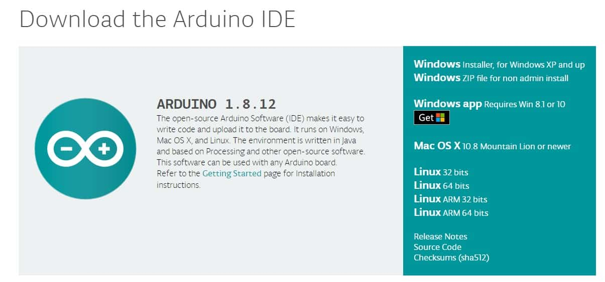
So, in this week, the first thing that I did is install arduion IDE. You can download arudino IDE from this Website.
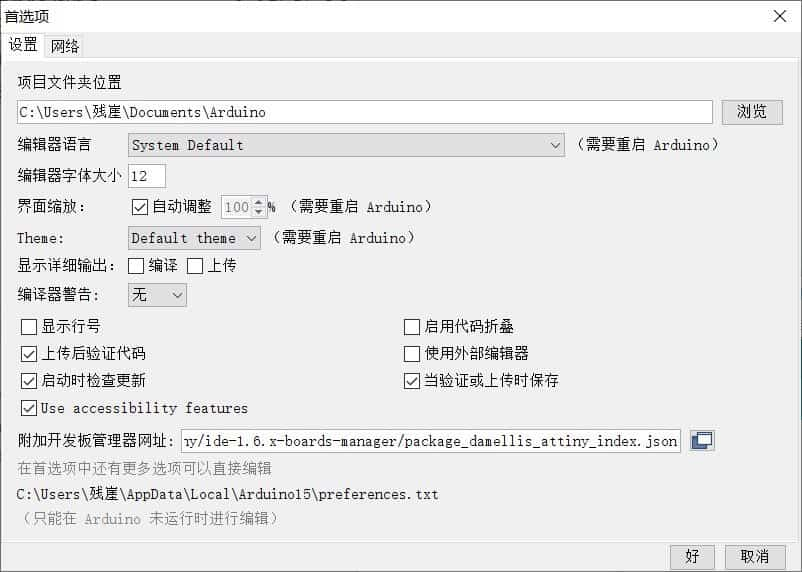
The first thing is I need to setting the Arduino IDE like is.
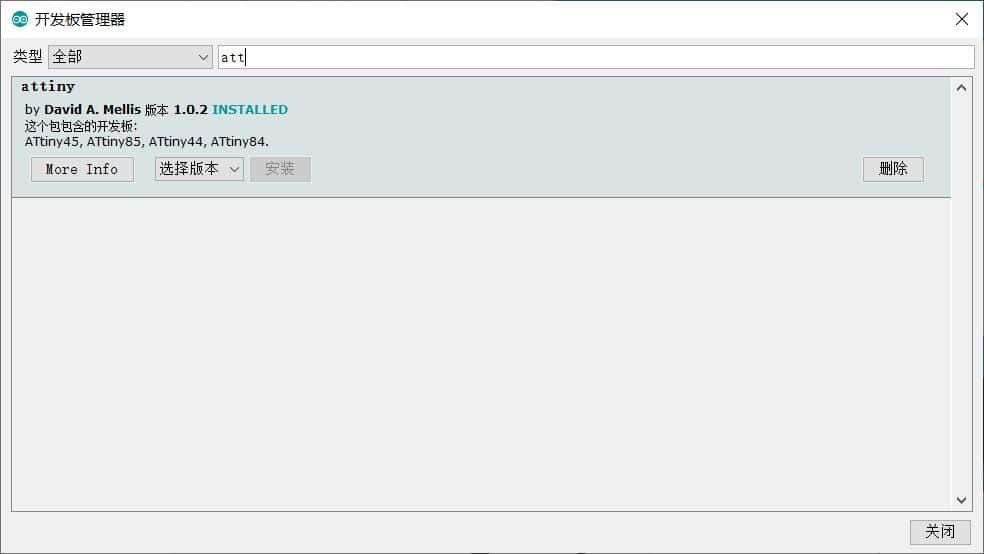
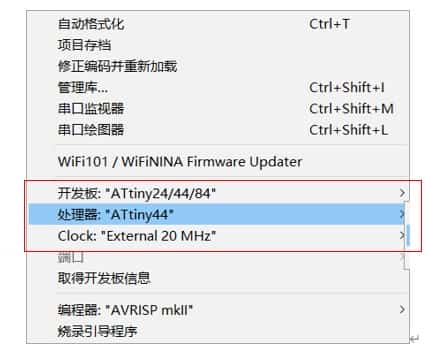
The next step is to add Attiny library and set the Arduino board. For that we need to go tools -> board -> board manager and then choose the Atiny24/44/84 as the board -> Attiny44 as the processor -> Extremal 20MHz as clock.
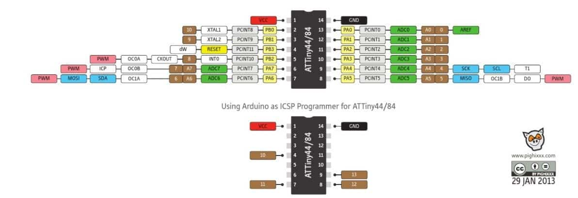
After doing the preparatory work, I began to program formally. And I also see the ATtiny scheme below to know each connection pin number in Arduino language. My scheme says that my INPUT (Button) is pin 2 and OUTPUT (Led) is pin 3.
⑴ Boton_Led_Flicker
I writhed the program taking in account these pins.
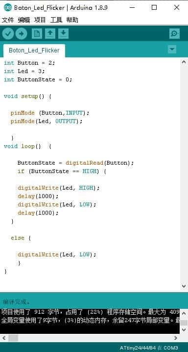
Then I used usbtiny to connect to my PCB board and compiled and download the program in Arduino to the PCB board.

Then I test my PCB board. So, I push the button in the board, and The LED lights start flashing.
⑵ Led_SOS
① Generality
SOS is a Morse code distress signal (▄ ▄ ▄ ▄ ▄ ▄ ▄ ▄ ▄ ▄ ▄ ▄ ▄ ▄ ▄ ▄), used internationally, that was originally established for maritime use.

②Program
I writhed the program code like this, three for loops are used to represent S, O, S.

③ Testing
I used usbtiny to connect to my PCB board and compiled and download the program in Arduino to the PCB board.
⑶ Boton_Led_SOS
On top of the previous program, I added a button. So, I writhed the program code like this:

I also used usbtiny to connect to my PCB board and compiled and download the program in Arduino to the PCB board. You can see how it worked in follow movie.
Following are a few different microcontroller architectures available in the market.
1) 8051
The Intel MCS-51 (also known as 8051) is a CISC architecture. These are available in 8-bit, 16-bit and 32-bit microcontrollers. 8051 silicon IP cores are typically smaller size, lower power compared to ARM Cortex-M and MIPS processors.


Then I have selected a board called 4WD MINIQ. This car board can be programmed by Arduino. This card contains: ATmega32U4 microcontroller、 Infrared receiving tube、RGB lamp、buzzer、key and so on.

Then I made a first test program by myself to use the buzzer which can play two different sounds.
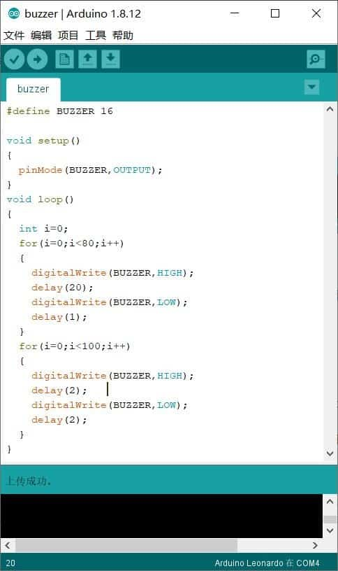
When I finish the program, I connected the board to the computer, and turned on the power. Then I clicked the download button on the Arduino IDE.
Next, I have selected a board called HC6800-MS. This car board can be programmed by Keil uVision5. This card contains as follow future.
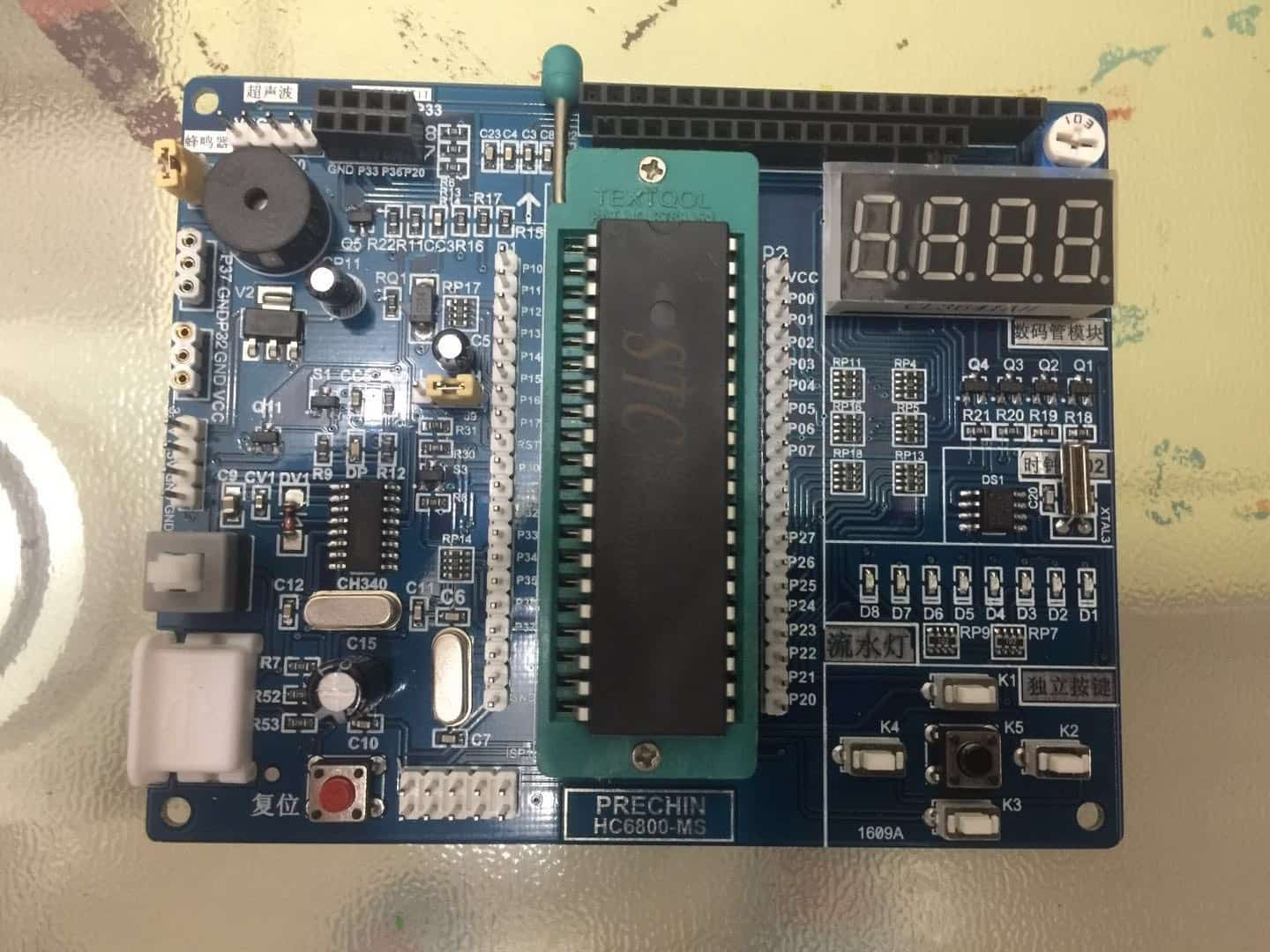
Then I made a test program by myself to use the LED. The LED are on from right to left. Here is the program.
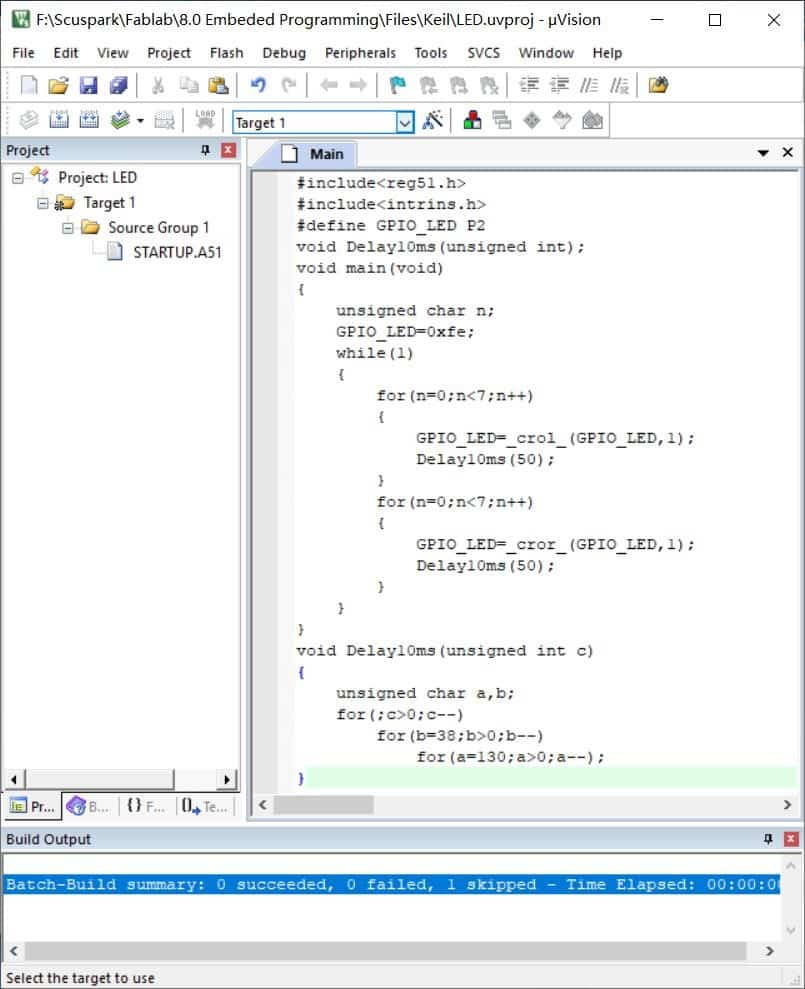
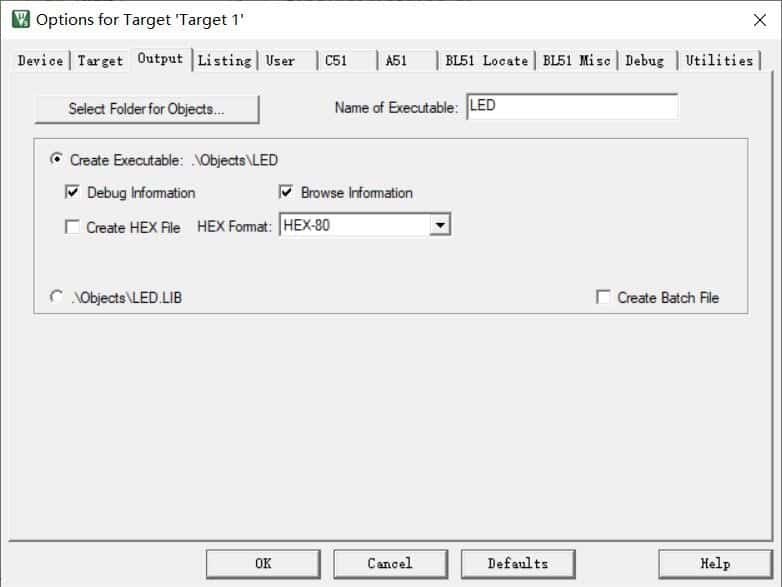
Then I generated the type of file which is .HEX.
The program is then downloaded to the board for verification.