week_07
Computer controlled machining
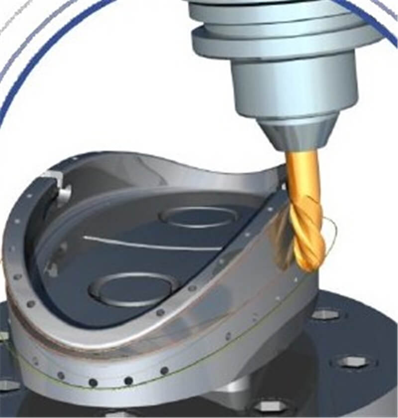
CNC (Computer Numeric Controlled) Machining, Milling or Turning utilizes automated machine tools that are operated by computers rather than being manually controlled or mechanically automated via cams alone. "Milling" refers to a machining process where the workpiece is held stationary while the tool spins and rotates around it. "Turning" occurs when the tool is held stationary and the workpiece spins and rotates. Using CNC systems, component design is automated using CAD/CAM programs. The programs produce a computer file that generates the commands needed to operate a particular machine, and then loaded into the CNC machines for production.
Efficiency: Aside from the need for periodic maintenance, CNC machines can operate almost continuously. One person can oversee the operation of several CNC machines at a time.
Ease of Use: CNC machines are easier to use than lathes and milling machines and greatly reduce the likelihood of human error.
Easy to upgrade: Software changes and updates make it possible to expand the machine's capabilities rather than replace the whole machine.
No prototyping: New designs and parts can be programmed directly into a CNC machine, eliminating the need to build a prototype.
Precision Parts made on a CNC machine are identical to each other.
Waste reduction: CNC programs can plan the lay out of the pieces to be machined on the material to be used. This allows the machine to minimize wasted material.
① Chip load: The physical size of the pieces or chips the bit cuts off the material.
Chipload = Feedrate / [RPM x number of flutes]
② Feed Rates: How quickly a machine can laterally move through the material being cut. Typically measured in Inches Per Minute (IPM).
Feed Rate = Spindle Speed (RPM)* Number of Flutes * Chip Load (inches) = Spindle Speed * Number of flutes * Chip Load = Answer inches/min
③ Speed Rates: The speed of the machines spindle. Typically measured in Revolutions Per Minute (RPM).
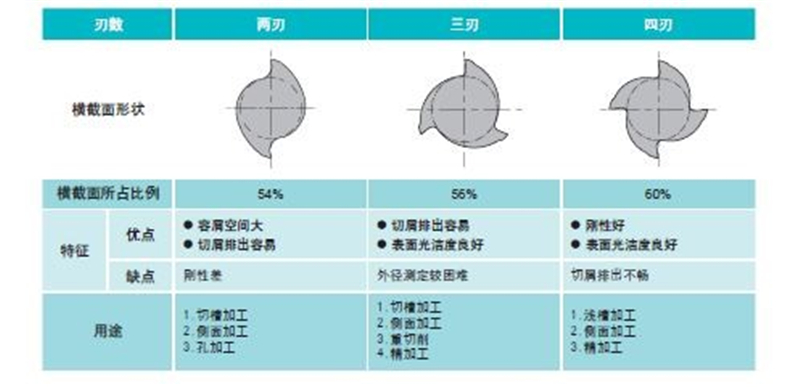
④ Flute: The number of cutting edges on a routing bit.
⑤ Toolpath: A coded route which a machine follows as a guide in order to cut.
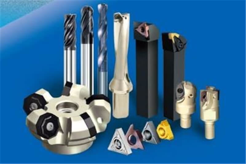
Each Bit has its own properties and the most important thing to look for is the Diameter, the Tooth the Flute, and the Cut Direction.
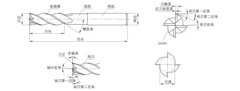
The Diameter describes the width of the cut made by the end mill.
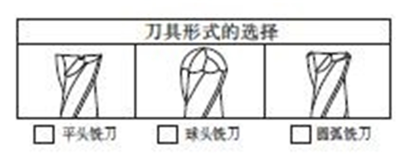
The Tooth is the tip shape (or head), there is different type of shapes designed for a particular purpose.
The Flute is the sharp edge of the end mill and each milling Bit has a certain number of flutes.
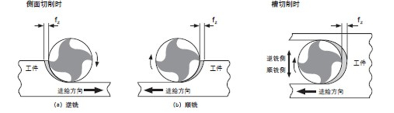
There are two distinct ways to cut materials when milling: Conventional Milling (Up) and Climb Milling (Down). The difference between these two techniques is the relationship of the rotation of the cutter to the direction of feed. In Conventional Milling, the cutter rotates against the direction of the feed. During Climb Milling, the cutter rotates with the feed.
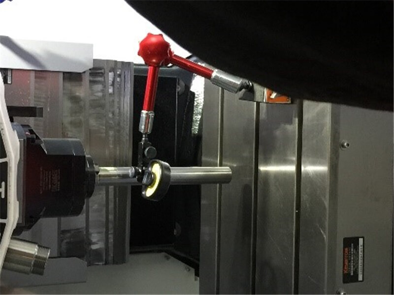
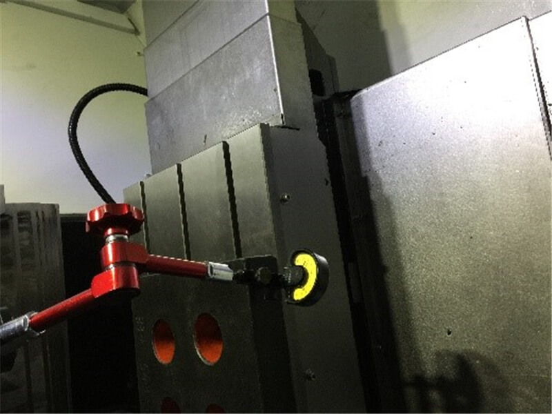
I used the square gauge, pole and lever table to check the machine's mechanical accuracy. When do mechanical precision detection, you must follow the steps and do not panic.
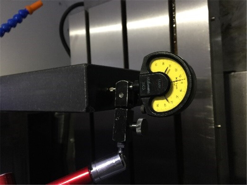
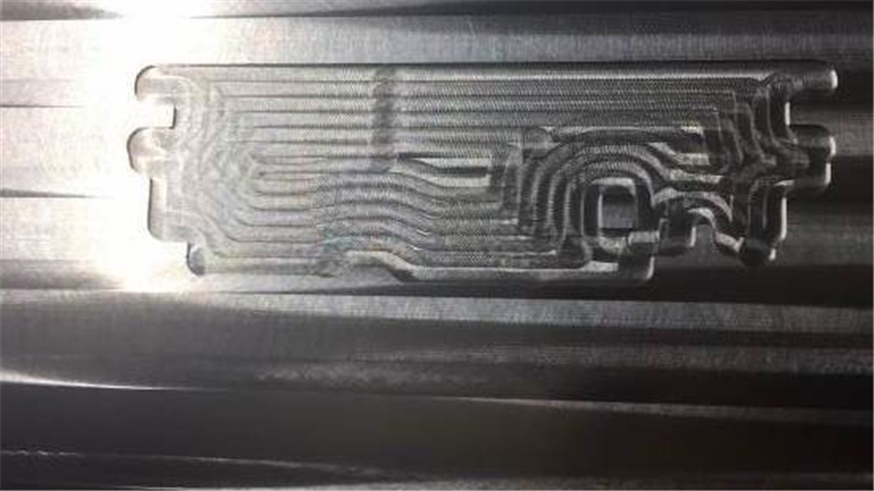
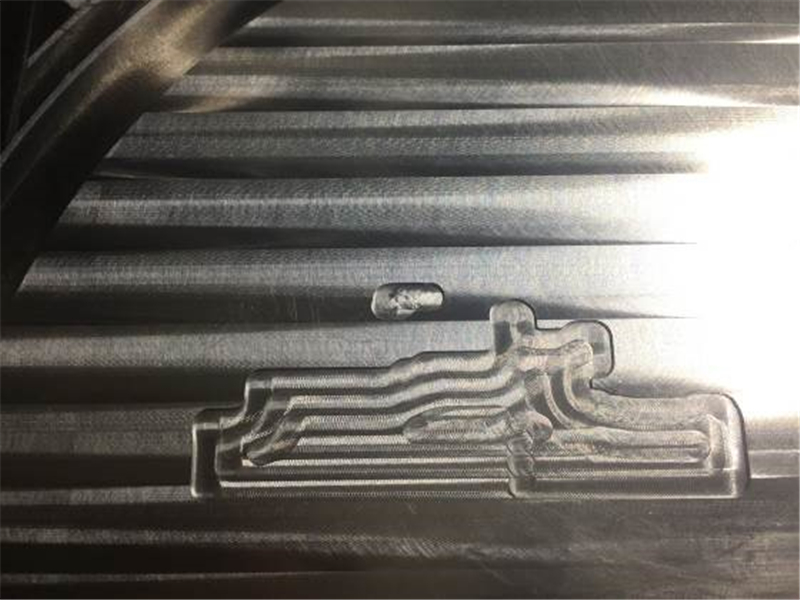
① Design the process model. I will use different feed speed for testing the arc corner. Example 1 has a feed speed of 1000 mm/min in the straight part and the arc part. Example 2 has a feed speed of 800 mm/min in the straight part and the arc part. Example 3 has a feed speed of 1000 mm/min in the straight part and has a feed speed of 360 mm/min in the arc part.
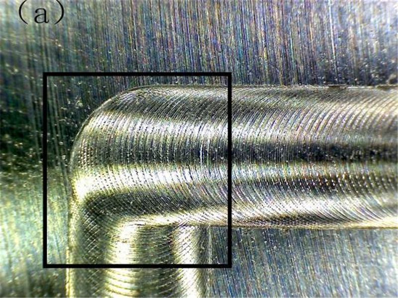
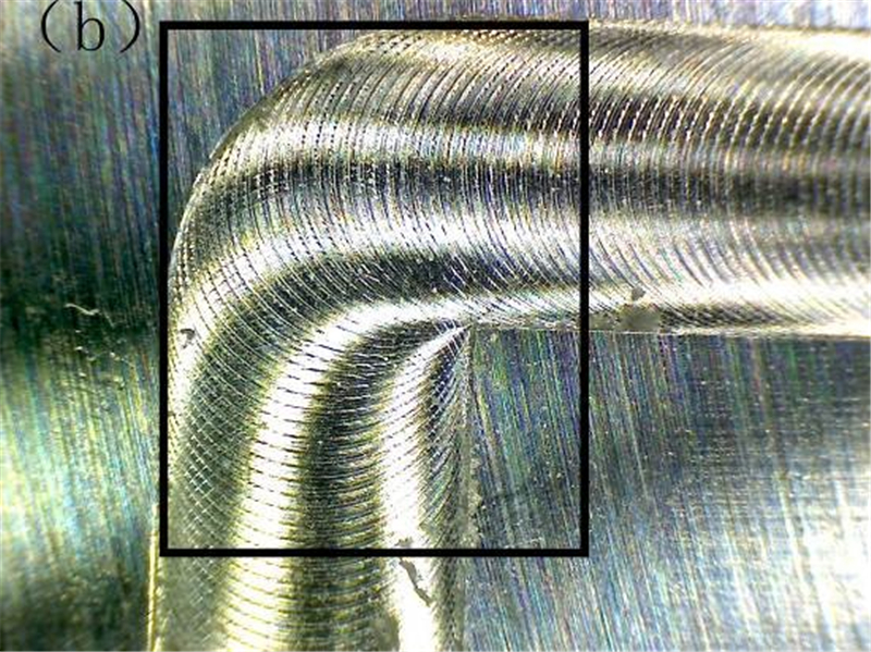
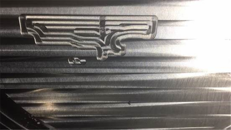
② Then I test the effect for cutting with different tool swing. The test results show that if we want to achieve good quality, we need to ensure that the tool swings below 1mm.
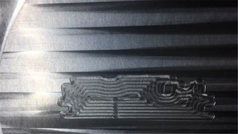
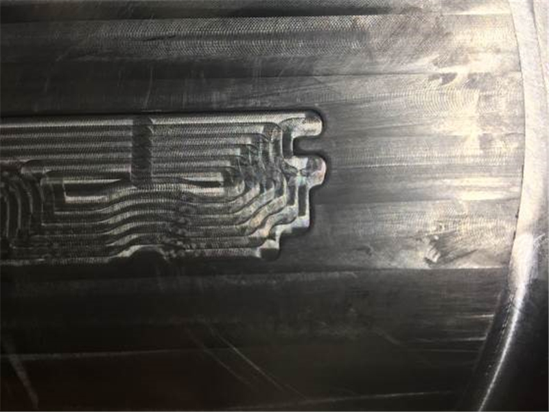
③ Finally, I tested the effect of speed on quality.
speed of mainshaft: 10000rmp. feed speed: 1500mm/min:
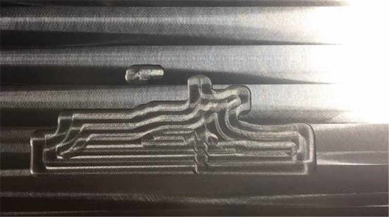
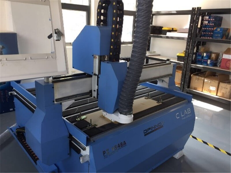
This week we have to design something big using 2D or 3D design software and process it using the CNC Router Machine. As there was a recent customer who was looking to get a custom frame of camera for him during this time, I decided to go ahead and document this job as we went forward in the training. I identified NG UG 11.0 as the best 2D and 3D software for making this project come to life.
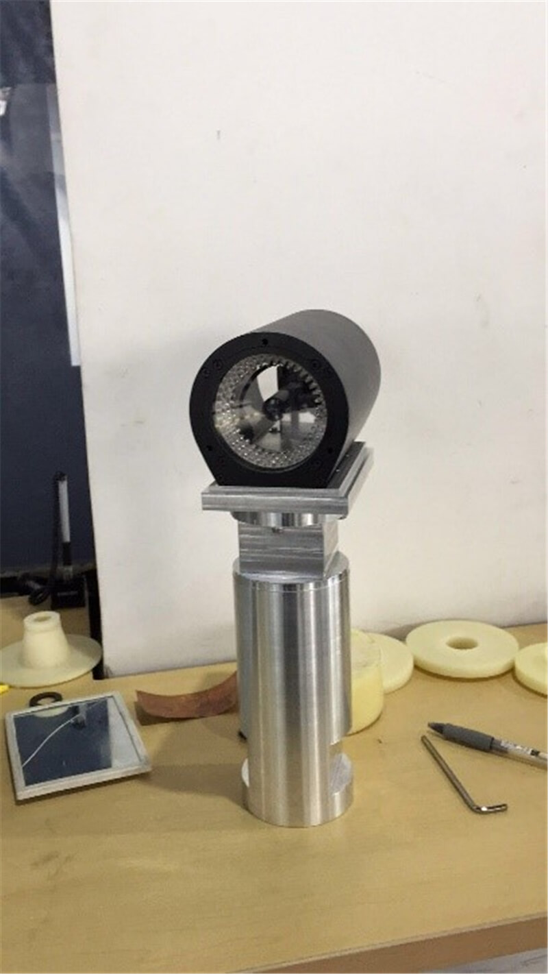
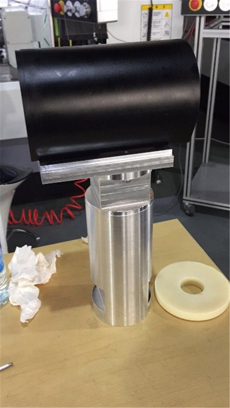
Objective: A simple stand for the camera in the processing center that should also be capable of dismantling for easy transportation.
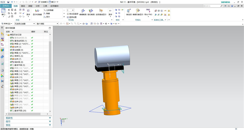
① The bottom bracket. I used the press plate connected the center machine and the bottom bracket of camera.
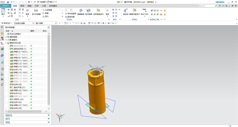
② Connection plate. I used the four screws connected the bottom bracket of camera and Connection plate.
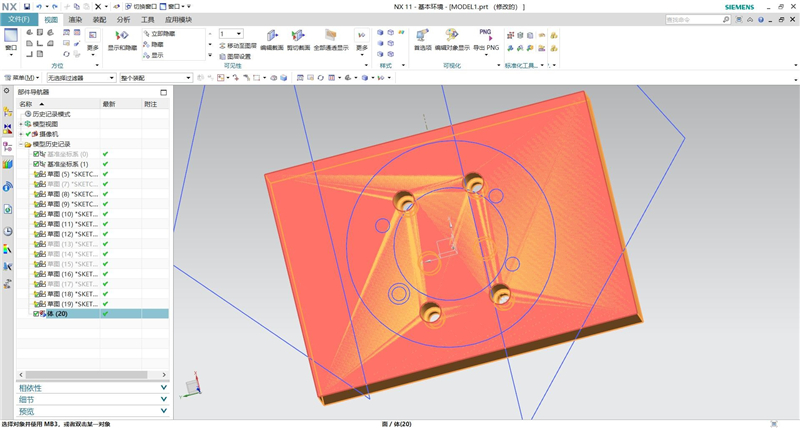
③ The frame of Camera (custom-made). I used the four screws connected Connection plate and the frame of Camera. I also used the locating-lock to locate.
① Created a aid and then created machining coordinate system and the workpiece.
② Created cutting tools.
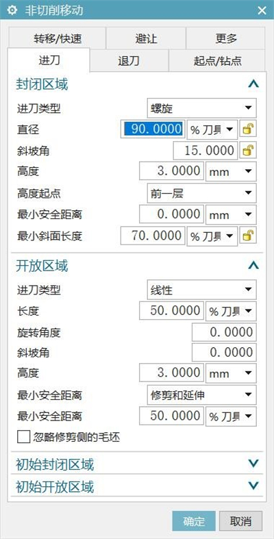
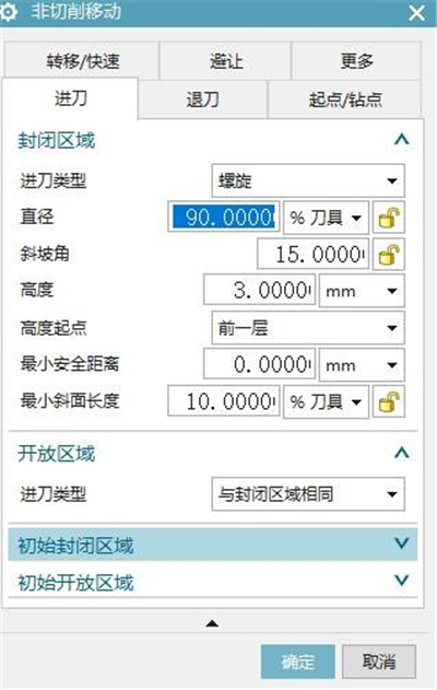
③ Create a new operation of cutting which is cavity mill. I used the mode of reciprocating cutting and cut 1mm within each layer. I also used the mode of cut feeding which is direct linear feeding in the open area. It should be noted that the feed mode is best to choose spiral feed or diagonal feed in the closed area. And also avoid choose the direct cutting. So, I don’t advocate using the fablab mods to generate the G-code. In the last few weeks of PCB processing, I found that the feed method is the bolt when I use the fablab modes. This feed method is too harmful for the endmill.
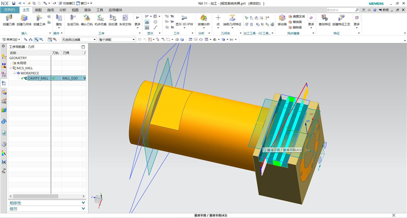
④ The rest can be processed by rotating the C axis using the same program.
⑤ In the similar way , generate the G-code of the connection board.
① Even if I simulate everything and search for good feed and speed, I am more comfortable to ask another person confirm my CNC job just to make sure I didn't miss anything. Thanks to my teacher to do that checkup.
② I used a three jaw chuck for clamping the bottom bracket (a hollow cylinder). And also used a flat tongs for clamping the connection board (aluminum alloy plate).
③ The following steps are the same steps that milling a PCB. You put the tool in your machine, make the zero where you plan it on your stock (very important). When everything is ready, you have to closed the door, wear some protection glasses and earmuff. Then you can start the machine. Make sure you are watching it to avoid any accident by pausing it.
④ The final product.

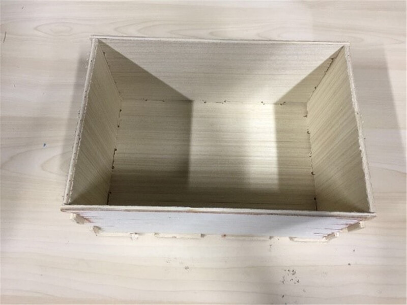
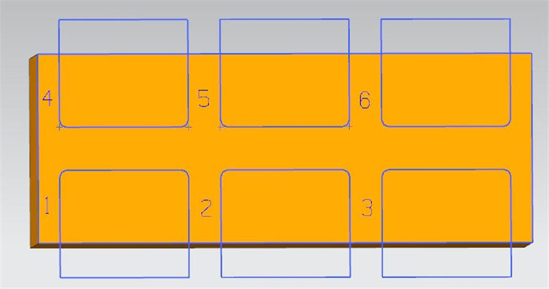
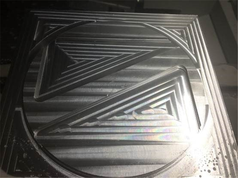
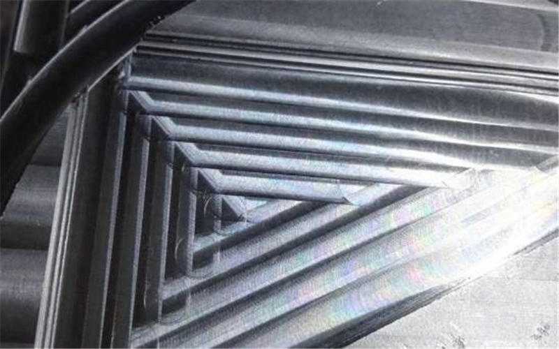
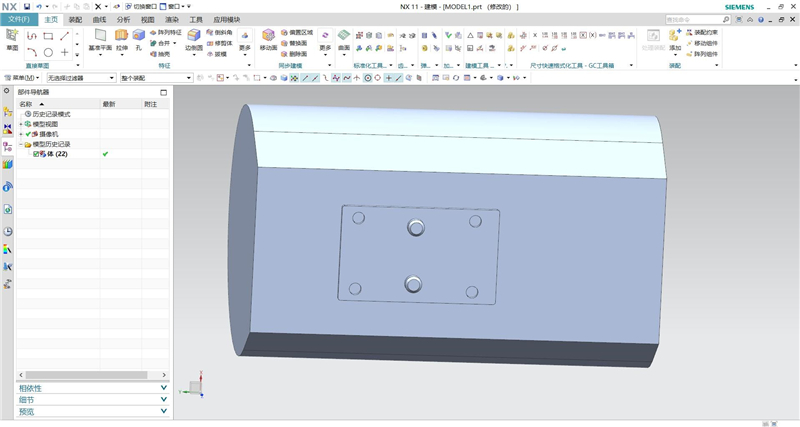
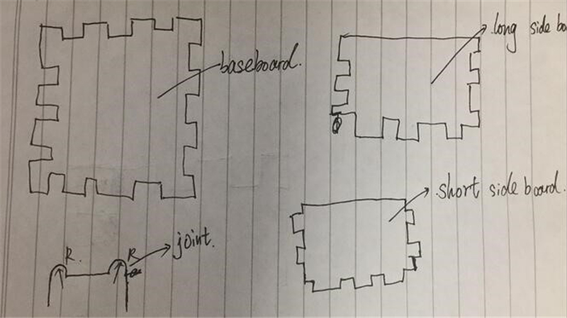
This week I also designed an assembly box with UG 11.0 to store some clutter. First, I simply designed the five sides of the box on the scratch paper, as shown in the figure below. In order to ensure the stability of the connection and ease of installation, I used the treatment of arc chamfering at the connection.
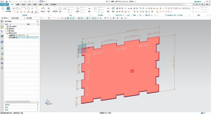
Through sketching, I designed the software through constraints, dimensions and so on.
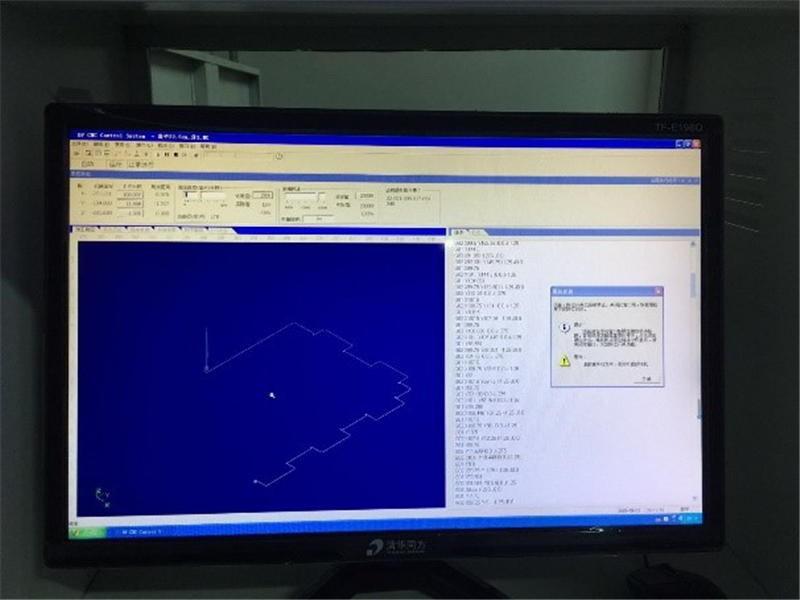
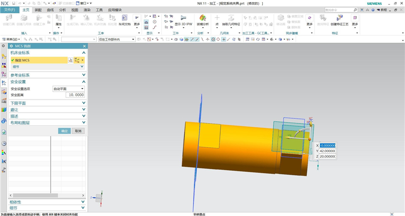
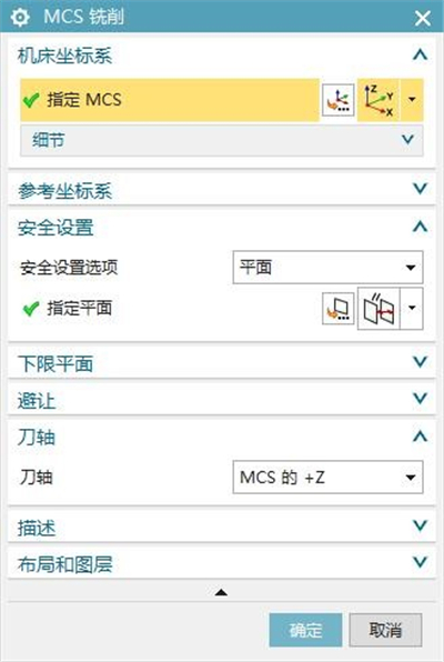
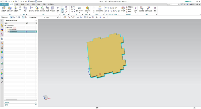
I was still programming NC program in UG, and first set the machining coordinate system and safe plane.
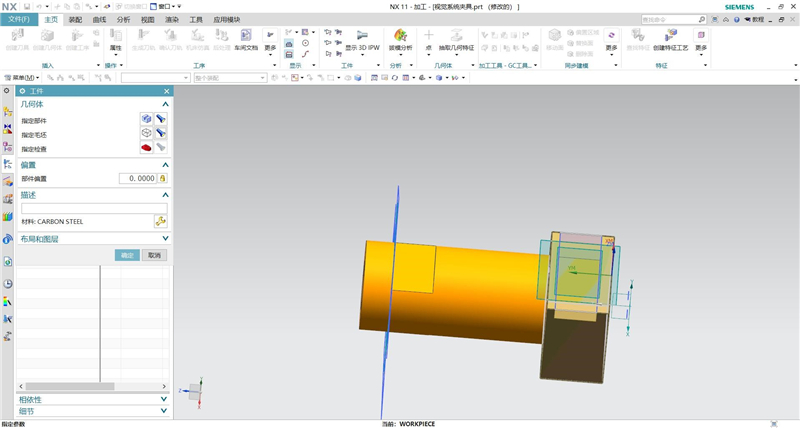
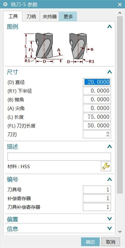
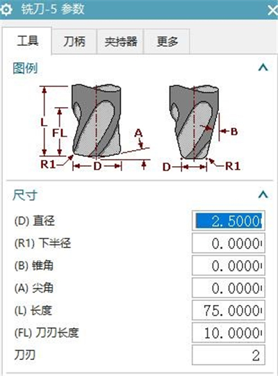
I plan to use 2.5mm end mill for cutting, so the tool and workpiece are set in the software.
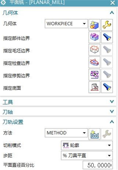
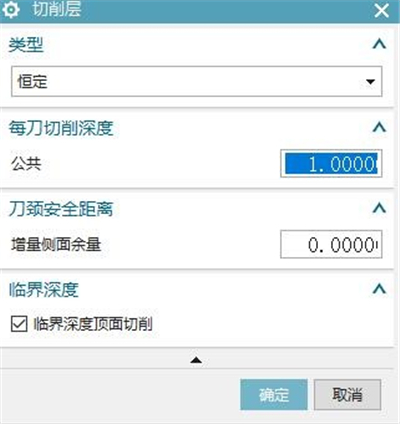
I adopt the plane milling mode, cutting range, cutting depth, cutting depth per tool, advance/retreat tool, speed, feed Settings are as follows.
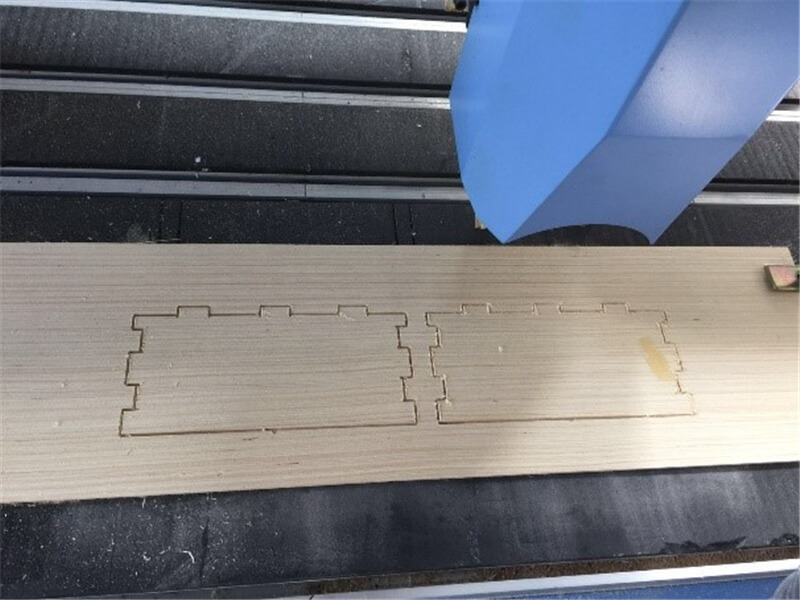
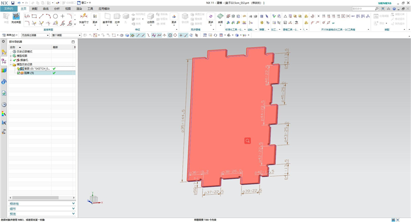
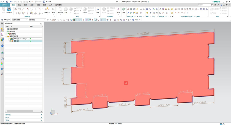
The cutting tool tracks are as follows. Set the other two types of boards in the same way.
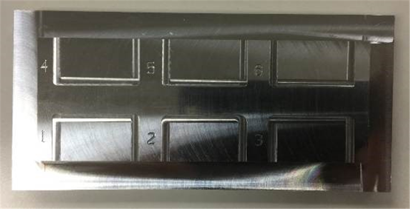
The processing went well this time. The processing videos and samples are as follows.