week_06
Electronics design
① Resistor: Limits the flow of the electrons through a circuit. The resistance is measured in ohms Ω. And an important aspect that we have to look at is the tolerance: how accurate it is. Current(I) = Voltage (V)/Resistor (R).
② Capacitors: They store energy in an electric field and they can control voltage spikes (they “clean” circuits “noise”). They can be polarized and un-polarized. Capacity =Charge (Q)/Voltage (V).
③ Inductor: stores energy also but in a magnetic field.
④ Wire: allows the communication between programmer and the board.
⑤ Switch: this component allows you to control whether an electric circuit is opened or closed. They are very important for user interaction.
⑥ Resonator: Provide a clock signal to the circuit, it gives work frequency to the micro-controller.
⑦ Diodes: their main function is to control the direction of the current flow. They are directional components.
⑧ Transistors: A transistor is a semiconductor component that can either amplify or switch electronic signals and electrical power. A voltage or current applied to one pair of the transistor's terminals controls the current through another pair of terminals.
⑨ Regulator: It has a capacitor after. It establishes the voltage that you will have after it. If you have a higher voltage, 5V for example, you can regulate what it goes out, 3.3V for example.
⑩ Micro-controller: Brain of the PCB, each pin could have different functionalities, which would be defined later with Fuses.
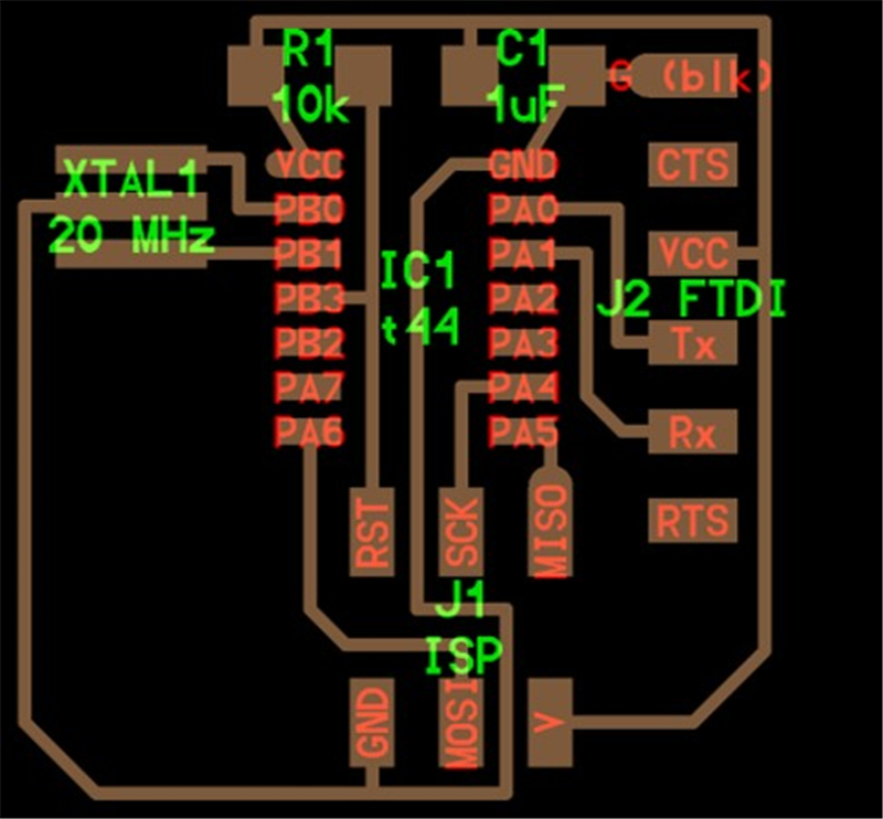
I will be started with basic electronics. The default hello world is here. I needed to add a push button and an LED to this existing design and resistor to ensure only the right amount of current passes through the LED. The Microcontroller (Attiny44) already has an 8Mhz internal clock. But I are adding an extra 20Mhz resonator for more accuracy and precise clock applications.
I choose the Autodesk Eagle PCB design software which is free for students and startups. This software is highly recommended and easy to use. Because of that the schematic can be realized in parallel to the board, so all the components that are inserted in the schematic are also inserted “physically” in the board. It can be downloaded from this website.
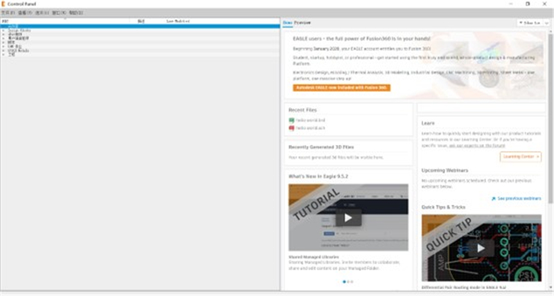
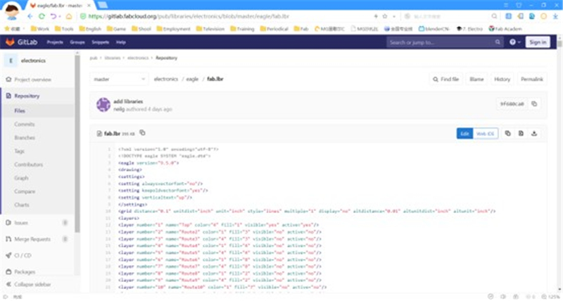
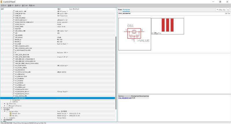
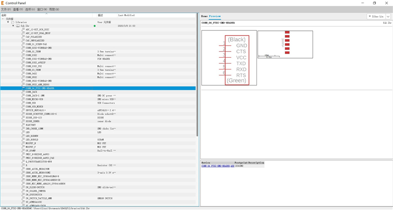
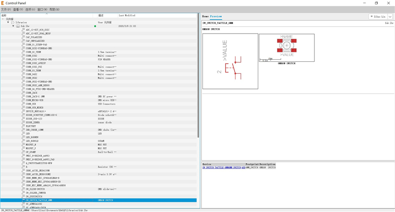
① First, I had to downloaded the file of Eagle Library and loaded it into the control panel window. This library contains the information of some components which include in addition to the technical characteristics, also the physical dimensions and the dimensions of the footprints.
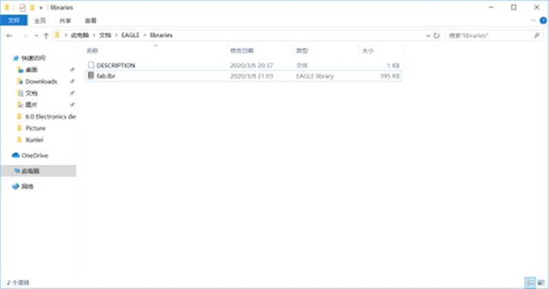
Save it in the Eagle’s library folder.
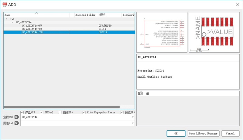
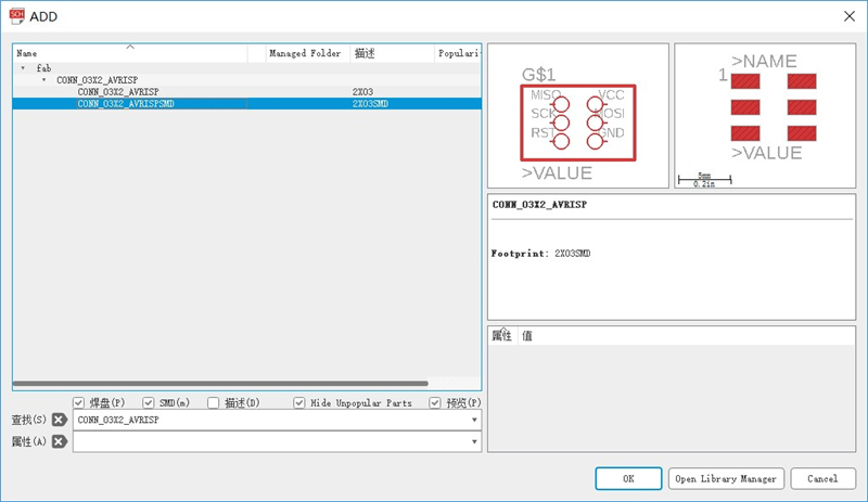
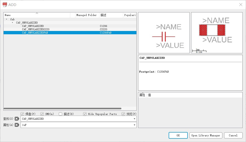
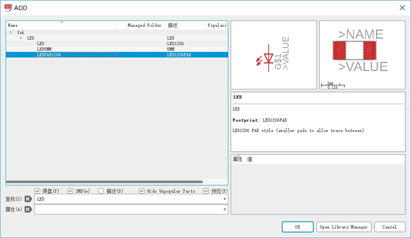
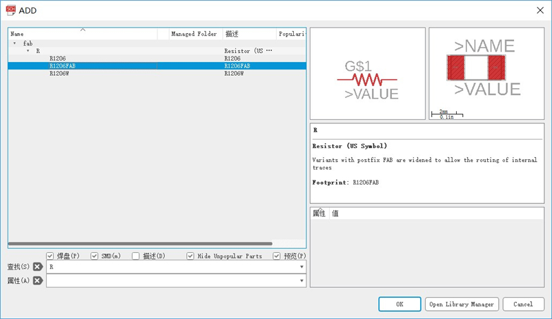
② Setp2: Using add tool to add components to my schematic. In the propped-up window, search for the require component and click OK.
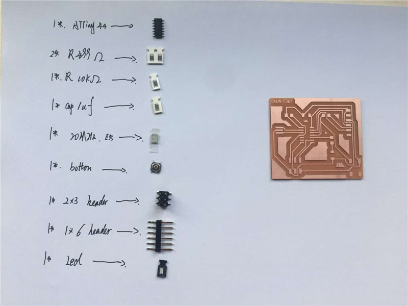
These are the components that I have used:
- ATTiny44-SSU, micro-controller;
- ACRISP, 2x3 header;
- CAP UNPOLARIZEDFAB, C1206FAB,1uf capacitor;
- RESONATOR, 20MHz crystal;
- LEDFAB1206, one green for button;
- RES-US1206FAB, resistors: (2) 499 Ω, (2) 10k Ω;
- FTDI-SMD-HEADER, 6-pin header;
- SWITCH 6mm*6mm button;
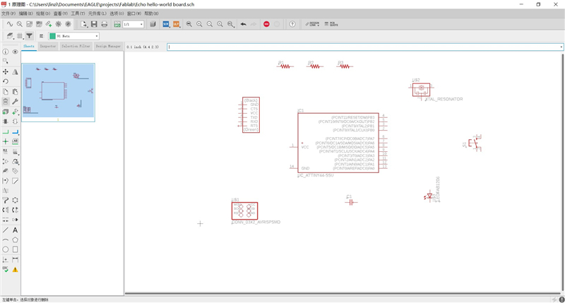
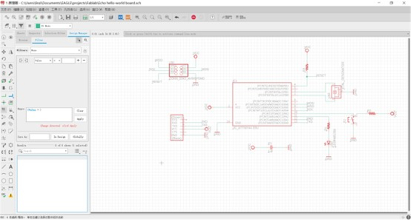
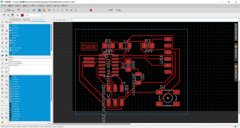
Setp3: Using the move and rotate tools to place them at the correct position. And then wire all of your schematic symbols together with nets and add values and part.
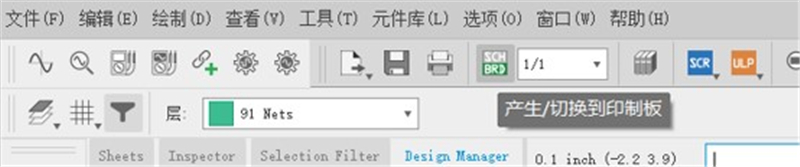
① Click on sch/brd tool to create a new board form the schematic.
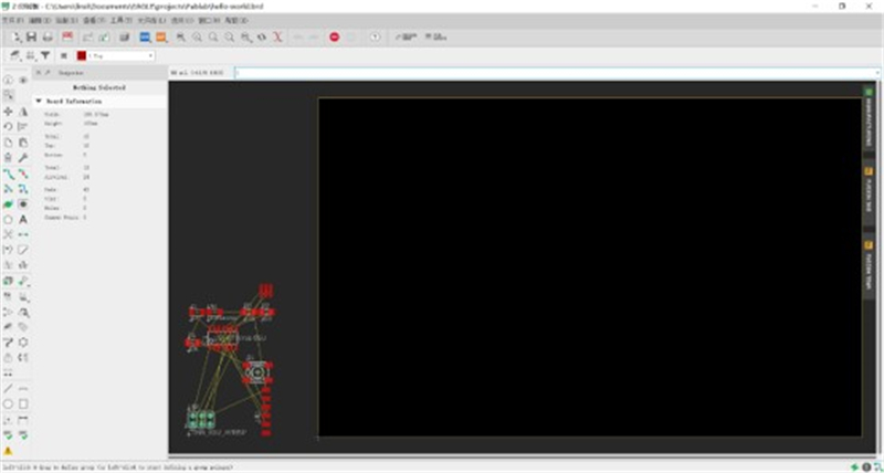
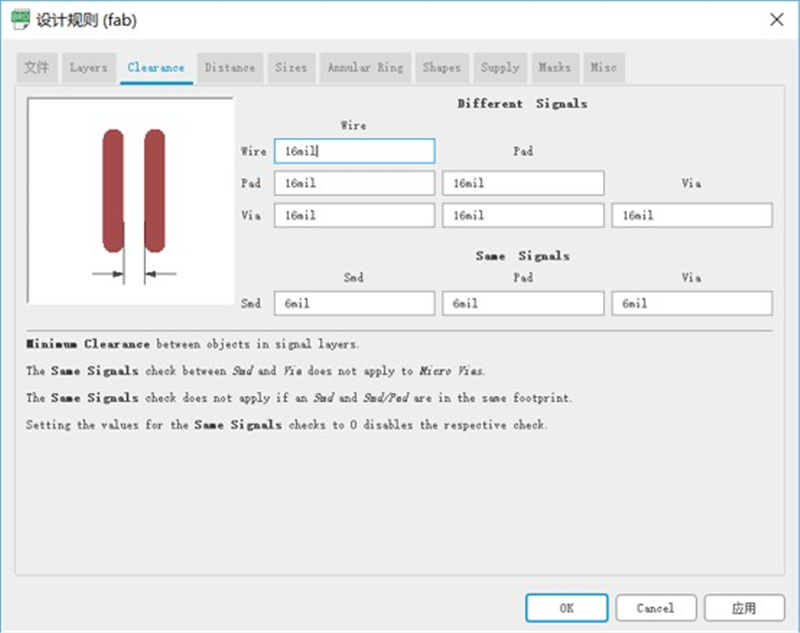
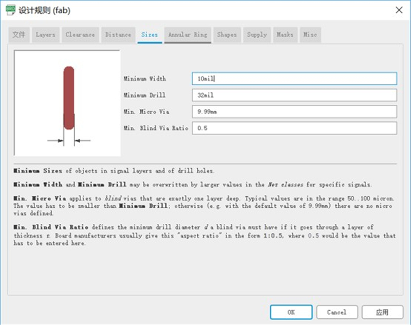
② Using the move, align and rotate tools to place the components on the board. Then set the design rules (size of the traces, clearance etc.). I used the rules of fab rules.
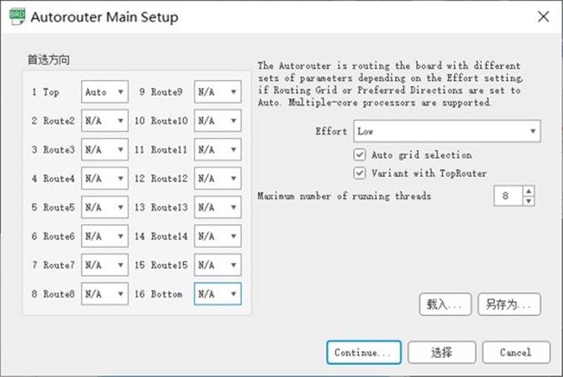
③ I have made three tries before obtaining a Ill-connected PCB. First, I had use the autorouter main setup tool. But the board of PCB have two layers, I didn’t know why. Then I have to find a way to s this problem on the Internet.
Then I set the default as following picture. But it still fails.
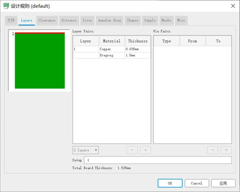
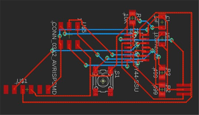
The third times, I fund that I set the Bottom layer was auto. Then I set the default as following picture.
Final board
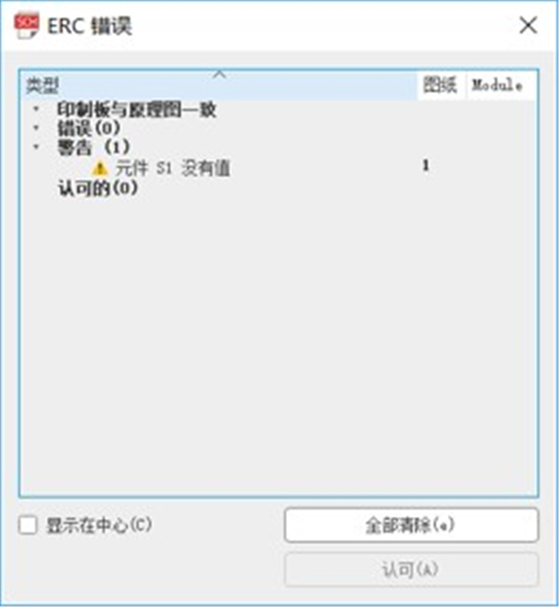
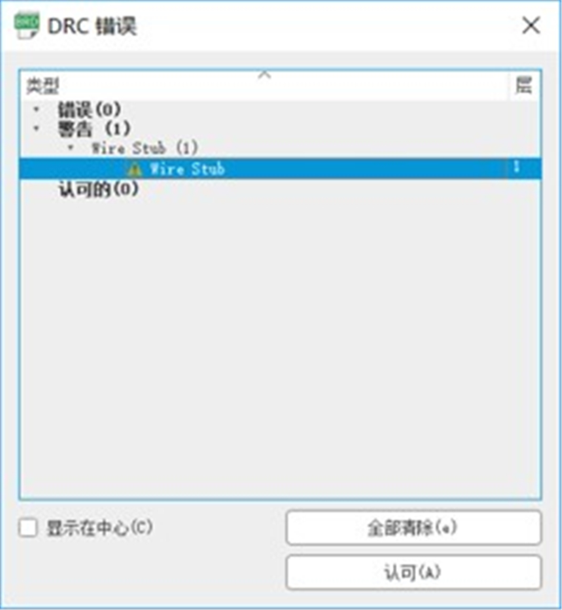
④ Run the ERC and DRC checks for any error. (Tools –> ERC/DRC).
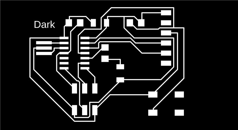
⑤ Hide all layers except top one(this has the traces).
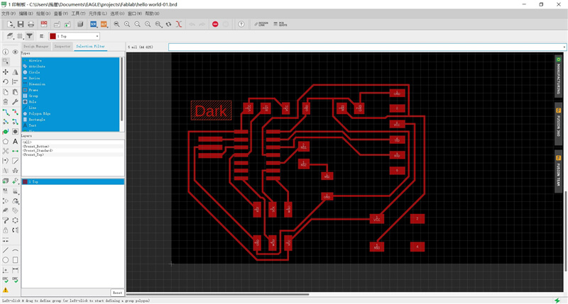
⑥ Export the file as PNG image.(File –> Export –> Image)

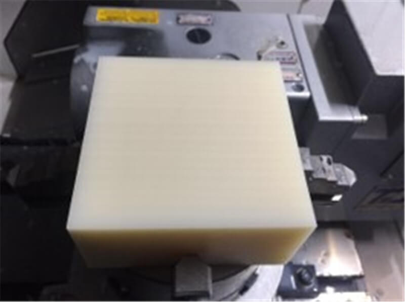
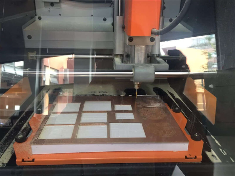
① I milling the sacrificial layer with a 10mm endmill to ensure the plane level.
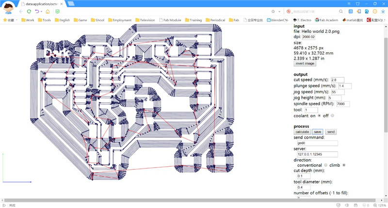
② Used Fab Modules. Then I imported the traces image, the image is in PNG format, with only black and white lines. I Choose the output format, as G-codes (.NC). Then, I choose the process, which is milling the PCB traces (1/64).
③ Use software of CIMCO and software of Vericut to check whether the G-codes is correct. But first time, I forgot the difference between the imperial system and the metric system. So, I deleted the code of G20. So, it is too small.
④ I fix the PCB to the milling machine plate use double side tape. I need to make sure that tape layer is smooth with no wrinkles. The surface of the material must be parallel to the x and y-axis of the machine..
⑤ I need measure the workpiece coordinate system, that is setting the origin of X axial, Y axial and Z axial(the method of try cutting).
⑥ Milling.
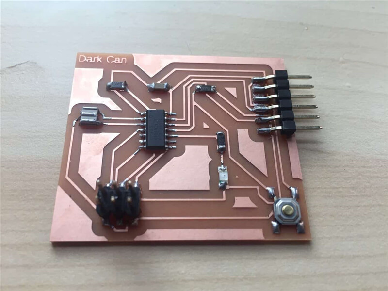
⑦ Once I had my milled PCB, I Int to work stuffing it with the components, starting with the ATtiny 44 pins. I found that useful to used the magnifying glass while soldering the components.
To test it physically we need to program it first. I have added a led with a button, so what are they going to do? I have to program it using Arduino IDE,
① Download Arduino software from this website.
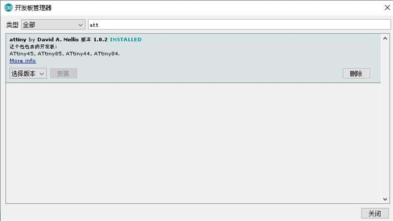
② In the Internet, I found a tutorials in this website. I can find a link to "install" ATtiny micro-controllers in Arduino libraries in Preferences.
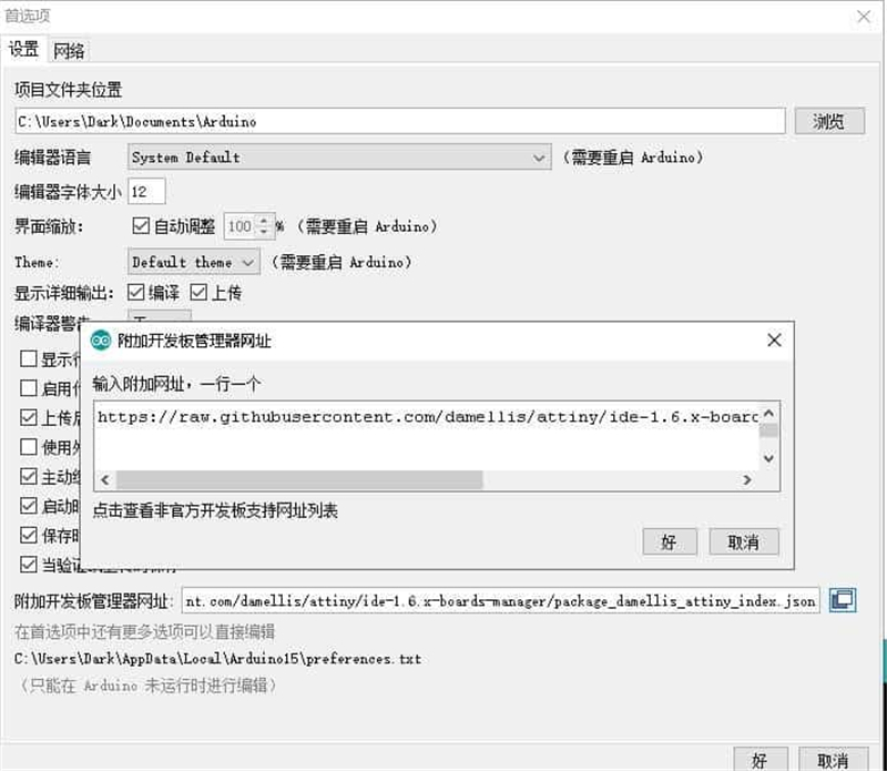
③ Select, in Boards Manager attiny and install it. Then, in Tools (Herramientas) select ATtiny44 as processor and USBtinyIPS as programmer.
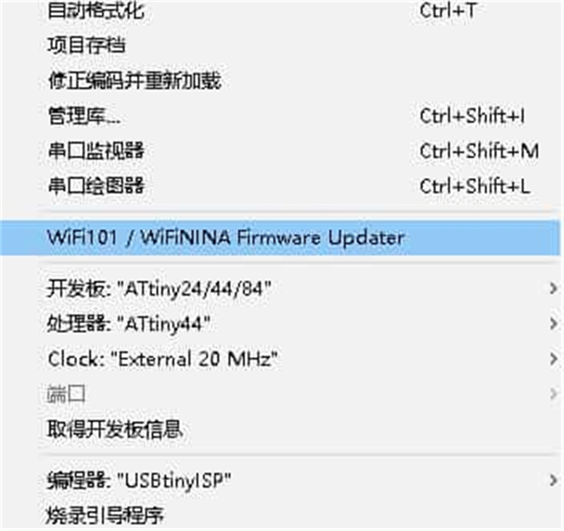
④ Burn Bootloader ("Quemar Bootloader") to say to USBtinyISP and PCB to be programmed with Arduino.
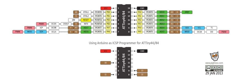
⑤ See ATtiny scheme below to know each connection pin number in Arduino language. My scheme says that my INPUT (Button) is pin 2 and OUTPUT (Led) is pin 3.
⑥ Write the program taking in account these pins, and programing the code to the PCB board,.
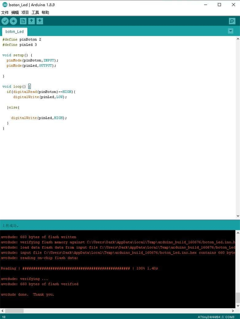
⑦ Test it with Arduinos.
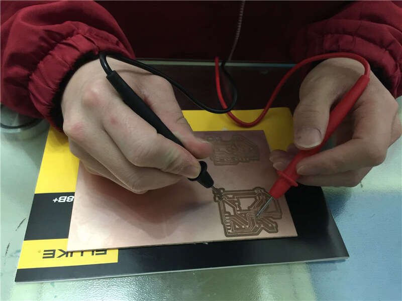
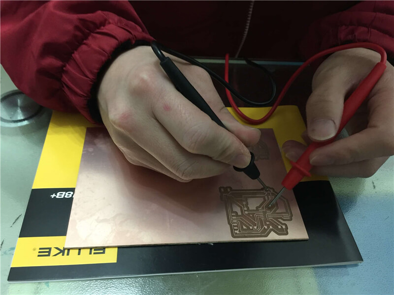
I test equipment in our lab to observe the operation of a micro-controller circuit board. With the digital multimeter I verified if each connector first of soldering the other components, to avoid burning them later, if it is not working Ill. Then, I use it to verify every connection pins and traces too, while I Ire soldering the other components. A digital multimeter (DMM) is a test tool used to measure two or more electrical values—principally voltage (volts), current (amps) and resistance (ohms). It is a standard diagnostic tool for technicians in the electrical/electronic industries.
Then, when I have PCB programmed and connected to the computer, I use the oscilloscope. An oscilloscope is a type of electronic test instrument that allows observation of varying signal voltages, usually as a two-dimensional plot of one or more signals as a function of time. Other signals (such as sound or vibration) can be converted to voltages and displayed too.