week_05
3D Scanning and Printing
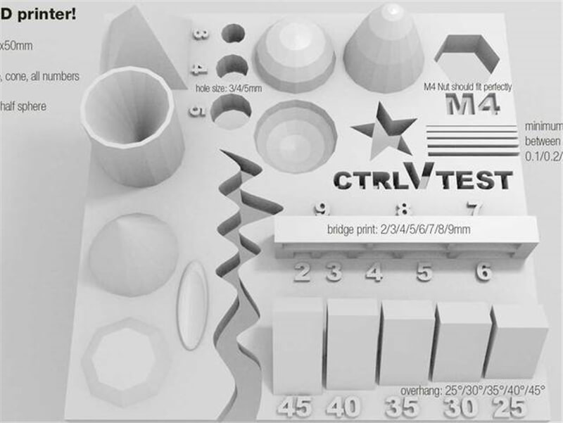
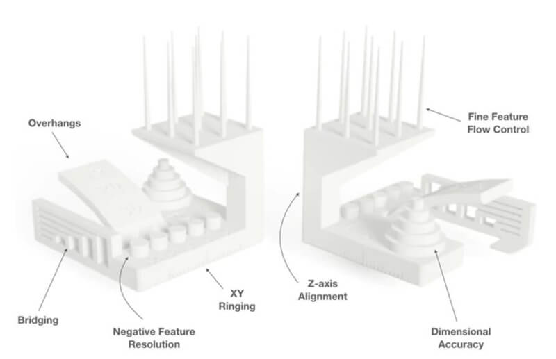
In order to test the different printers, the best option is to print a part that shows how the printer behaves in different situations. To do this, I have used a file from thingiverse.
Every 3D printer builds parts based on the same main principle: a digital model is turned into a physical three-dimensional object by adding material a layer at a time. This where the alternative term Additive Manufacturing comes from.3D printing is a fundamentally different way of producing parts compared to traditional subtractive (CNC machining) or formative (Injection molding) manufacturing technologies.
① The sci-fi author, Arthur C. Clarke, was the first to describe the basic functions of a 3D printer back in 1964.
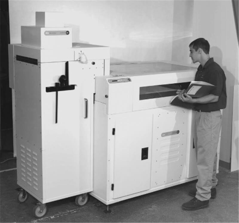
② The first 3D printer was released in 1987 by Chuck Hull of 3D Systems and it was using the "stereolithography" (SLA) process.
③ In the 90's and 00's other 3D printing technologies were released, including FDM by Stratasys and SLS by 3D Systems. These printers were expensive and mainly used for industrial prototyping.
④ In 2009, the ASTM Committee F42 published a document containing the standard terminology on Additive Manufacturing. This established 3D printing as an industrial manufacturing technology.
⑤ In the same year, the patents on FDM expired and the first low-cost, desktop 3D printers were born by the RepRap project. What once cost $200,000, suddenly became available for below $2,000.
⑥ According to Wohlers the adoption of 3D printing keeps growing: more than 1 million desktop 3D printers were sold globally between 2015 and 2017 and the sales of industrial metal printers almost doubled in 2017 compared to the previous year.
It is important to understand that 3D printing is a rapidly developing technology. It comes with its unique set of advantages, but also lags behind traditional manufacturing in some ways.
① Benefits of 3D printing
A. Geometric complexity at no extra cost
B. Very low start-up costs
C. Customization of each part
D. Low-cost prototyping with very quick turnaround
E. Large range of (specialty) materials
② Limitation of 3D printing
A. Lower strength & anisotropic material properties
B. Less cost-competitive at higher volumes
C. Limited accuracy & tolerances
D. Post-processing & support removal
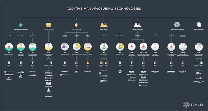
The ISO/ASTM 52900 standard categorized all different types of 3D printing under one of these seven groups:
① Material Extrusion (FDM): Material is selectively dispensed through a nozzle or orifice.
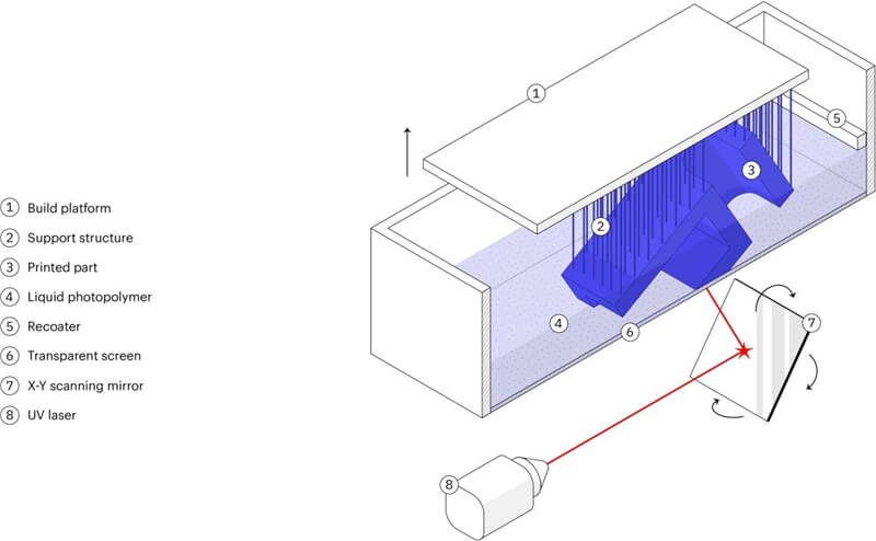
② Vat Polymerization (SLA & DLP): Liquid photopolymer in a vat is selectively cured by UV light.
③ Powder Bed Fusion (SLS, DMLS & SLM): A high-energy source selectively fuses powder particles.
④ Material Jetting (MJ): Droplets of material are selectively deposited and cured.
⑤ Binder Jetting (BJ): Liquid bonding agent selectively binds regions of a powder bed.
⑥ Direct Energy Deposition (LENS, LBMD): A high-energy source fuses material as it is deposited.
⑦ Sheet Lamination (LOM, UAM): Sheets of material are bonded and formed layer-by-layer.
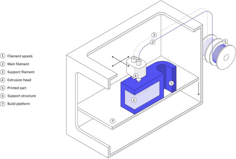
In FDM, a spool of filament is loaded into the printer and then fed to the extrusion head, which is equipped with a heated nozzle. Once the nozzle reaches the desired temperature, a motor drives the filament through it, melting it.
The printer moves the extrusion head, laying down melted material at precise locations, where it cools and solidifies (like a very precise hot-glue gun). When a layer is finished, the build platform moves down and the process repeats until the part is complete.
SLA and DLP are similar processes that both use a UV light source to cure (solidify) liquid resin in a vat layer-by-layer. SLA uses a single-point laser to cure the resin, while DLP uses a digital light projector to flash a single image of each layer all at once.
After printing, the part needs to be cleaned from the resin and exposed to a UV source to improve its strength. Next, the support structures are removed and, if a high quality surface finish is required, additional post-processing steps are carried out.
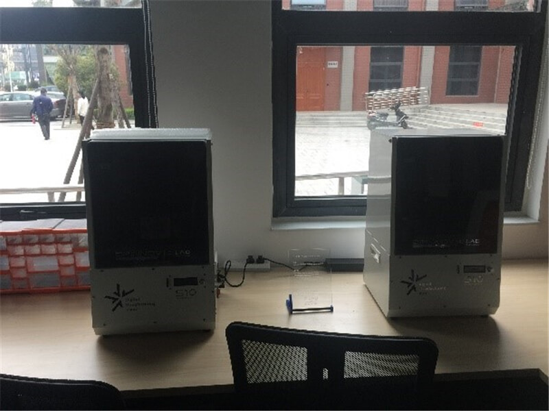
In this part of the weekly assignment, I will characterize two different machines. The first one is FDM D420 which made by Dpinnov Company. The second, is the S10 3Dprinter of Digital light processing. In order to test the different printers, the best option is to print a part that shows how the printer behaves in different situations.
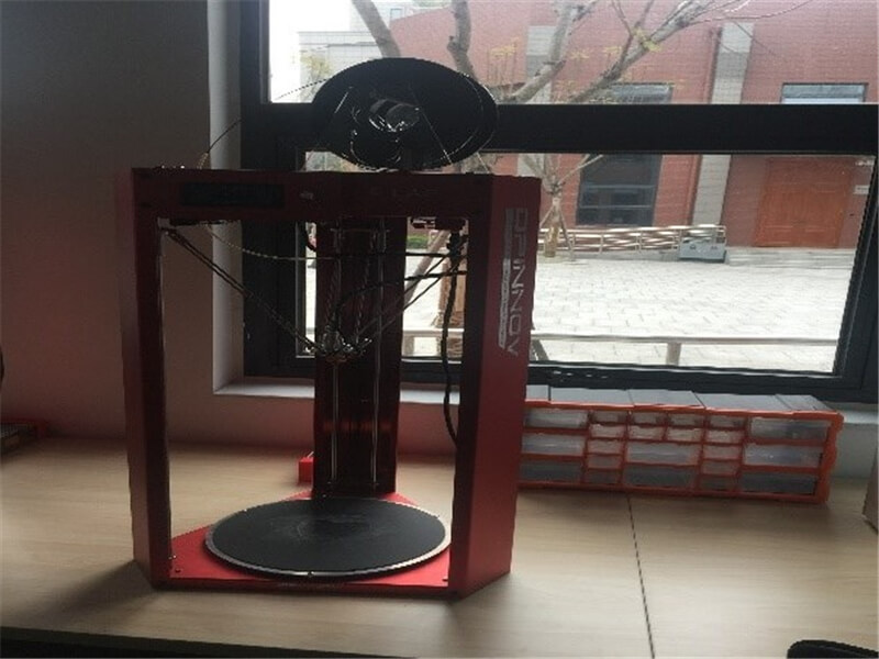
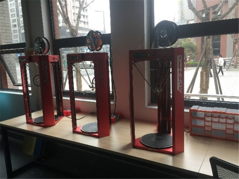
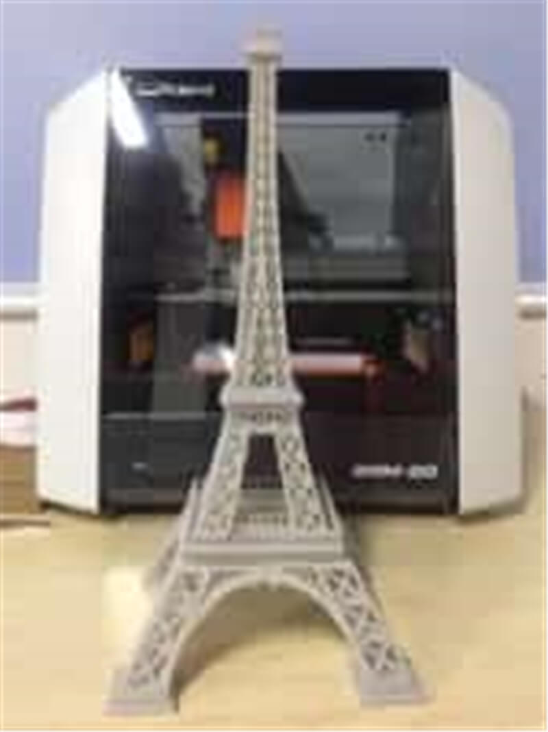
① FDM D420 3D printer
Area (x, y, z): D100mm*270mm. How to print: SD card. Nozzle diameter:0.4mm. Filament diameter: 1.75mm. Axis movement: Delta.
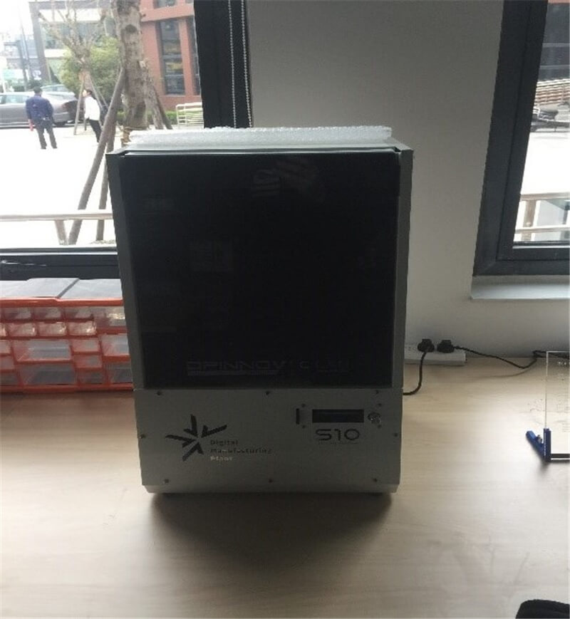
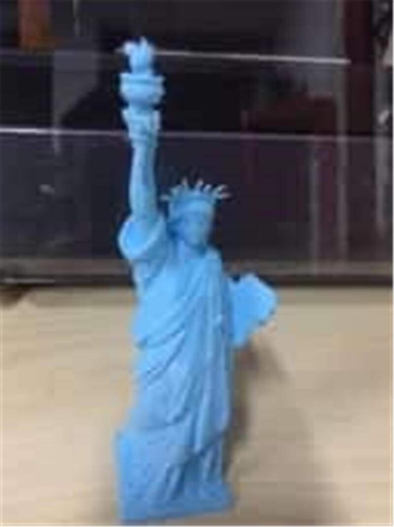
② S10 3D printer
Area (x, y, z): 130mm*130mm*165mm. How to print: SD card. Print thick:0.025mm-0.1mm. Power: 60W. Materials: photosensitive resin.
①A test on thingiverse
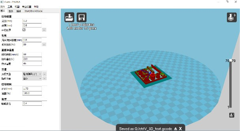
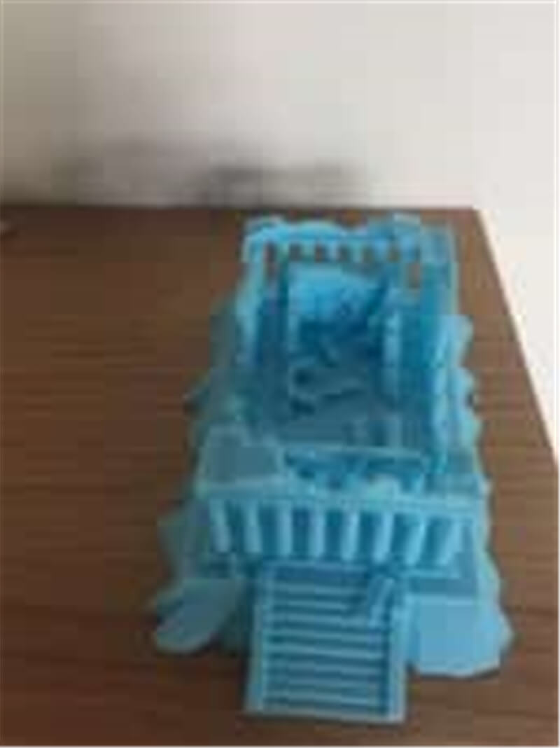
① FDM D420 3D printer
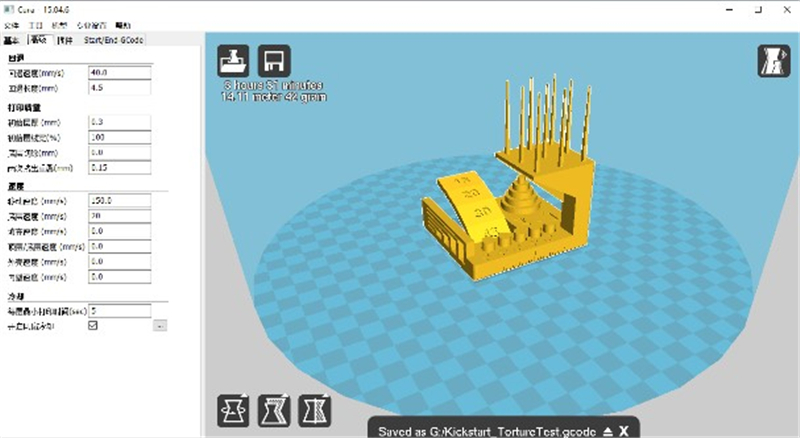
Layer height: 0.2mm, Wall line count:0.8mm, Top layers:0.8mm, Bottom layers:0.8mm, Infill: 20%, Speed: 60mm/s, Nozzle temp: 210℃, Bed temp: 45℃, Material: 1.75mm PLA, Nozzle diameter: 0.4mm, Support type: extend to platform.
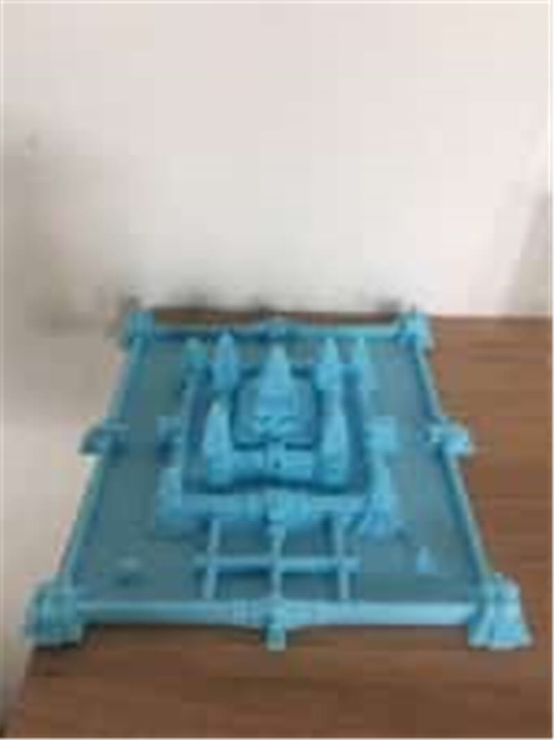
② S10 3D printert
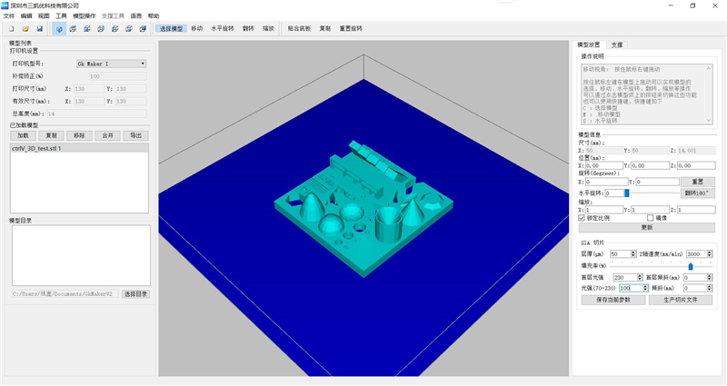
Layer height: 50um, Z axis speed: 3000mm/s, Infill: 80%, The first layer of light intensity: 230, light intensity: 100, Material: photosensitive resin.
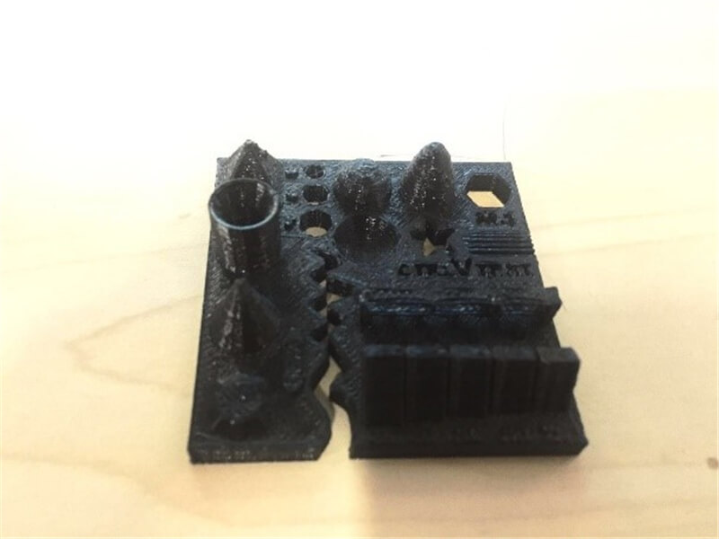
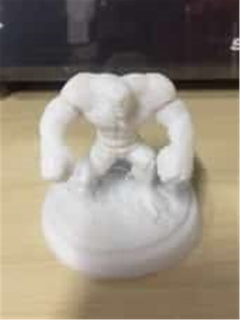
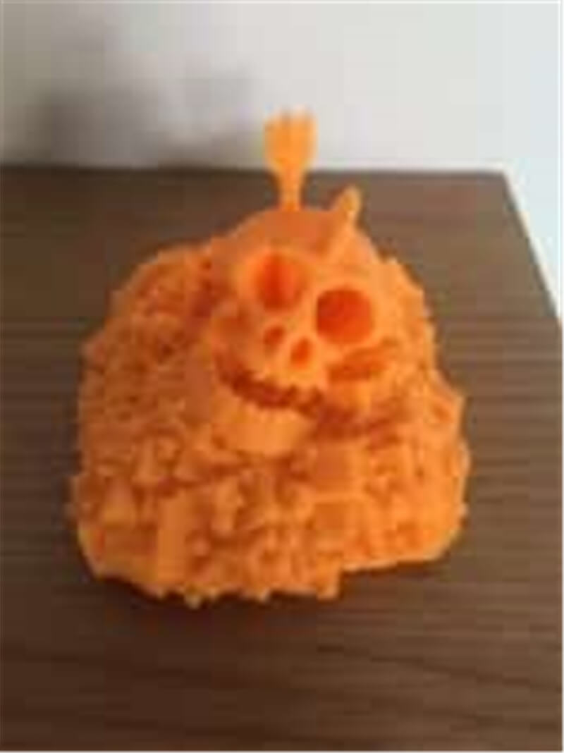
① FDM D420 3D printer
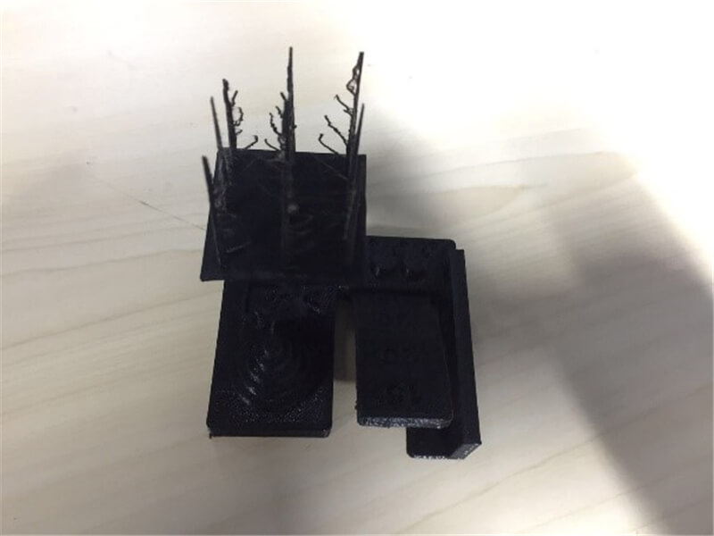
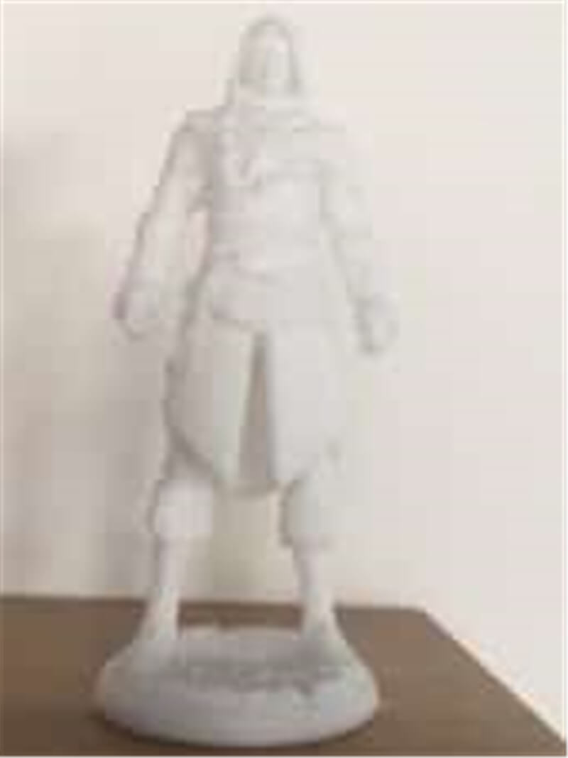
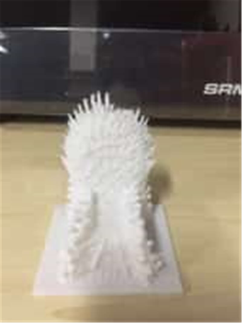
② S10 3D printer
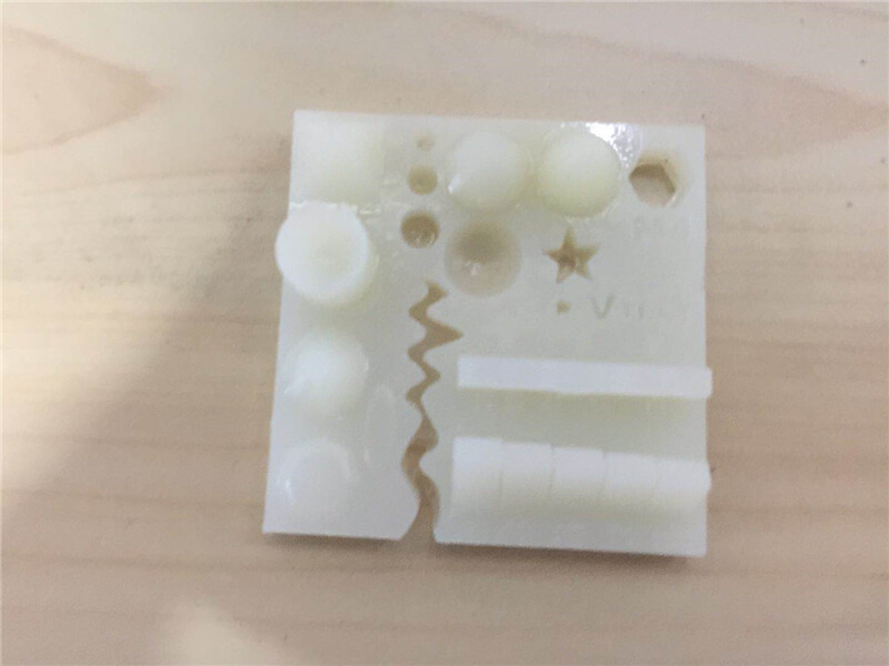
Photocurable printers have higher accuracy.
My individual assignment for this week was to design and make a 3D printed part that could not be made by 3-axis NC machining.
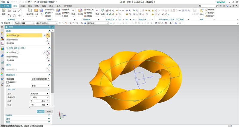
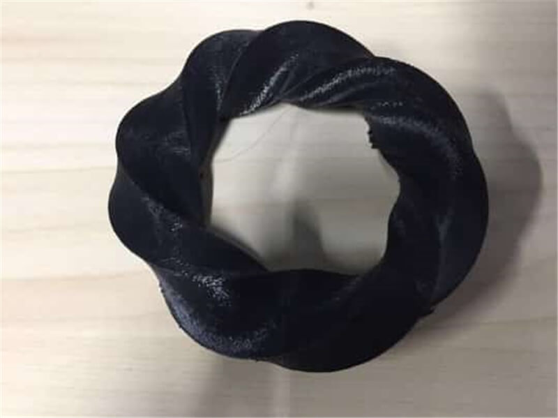
The Mobius ring is a ring formed by twisting a long plane by 720 degrees and connecting it first. Reducing cutting is cutting by cutting tool moving high and rotating speed or workpiece moving high speed cutting tool rotating speed cutting workpiece, the workpiece must be fixed clamping. However, mobius rings are curved at every Angle, and there is no place for clamping, so mobius rings can only be produced through additive processing.
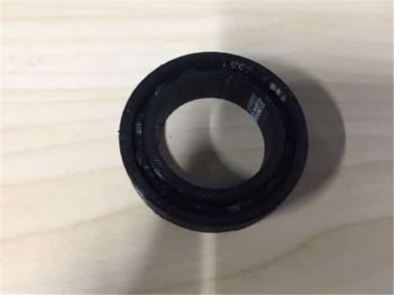
Rolling bearing is generally composed of an inner ring, an outer ring, a rolling body and a cage. Its structure is very complex, subtraction cutting requires the inner ring, outer ring, rolling body and cage separately processing, and then with a professional process for installation. And cannot be formed by reducing cutting once. Therefore, only through additive manufacturing similar to 3D printing can it be processed and formed once to ensure the integrity and accuracy of its structure.
① The mobius ring
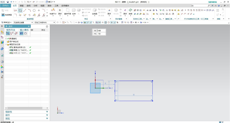
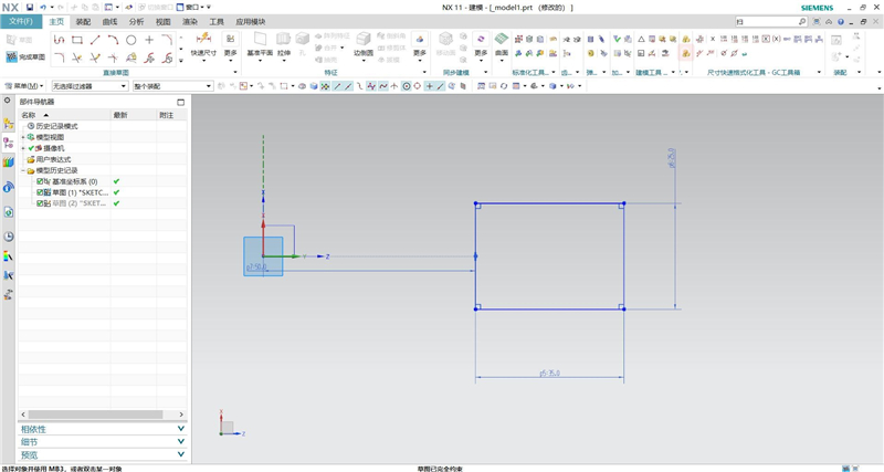
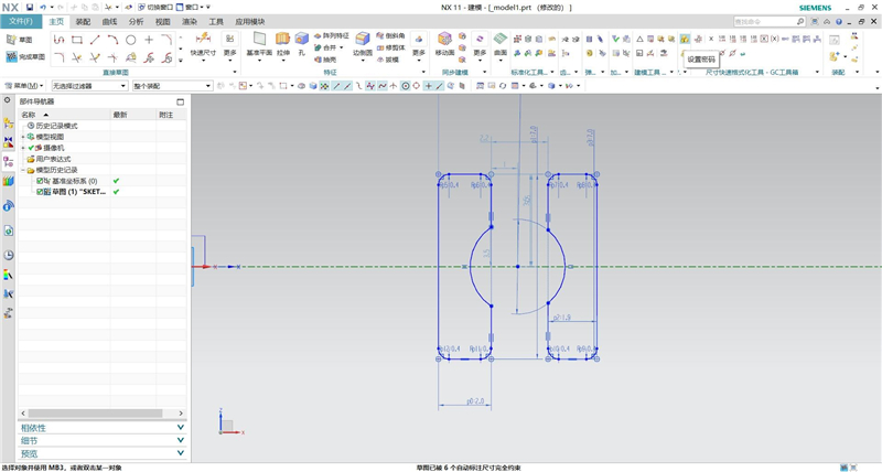
I started out in NX UG. The first thing I use the rectangle command and then draw an arbitrary on the Z-X plane.
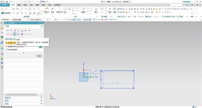
Use the geometric constraint command to align the center point on the left side of the rectangle with the origin of the coordinate system.
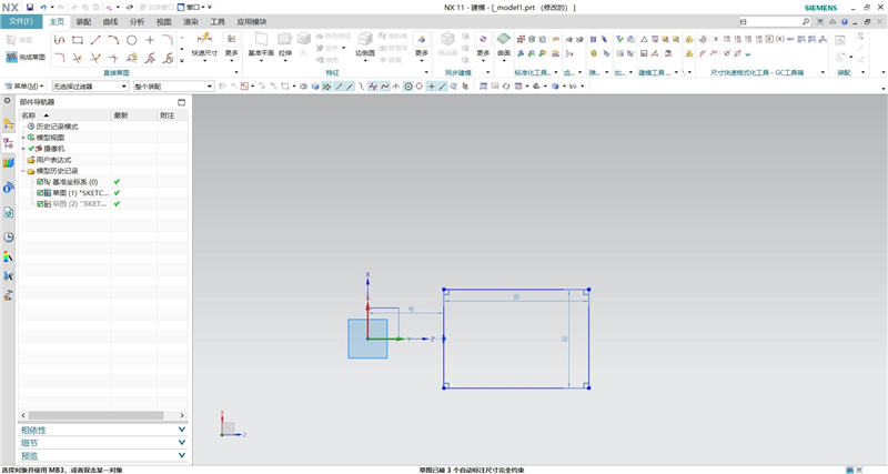
Use the linear size (or quick size) to label the sizes shown in the following figures.
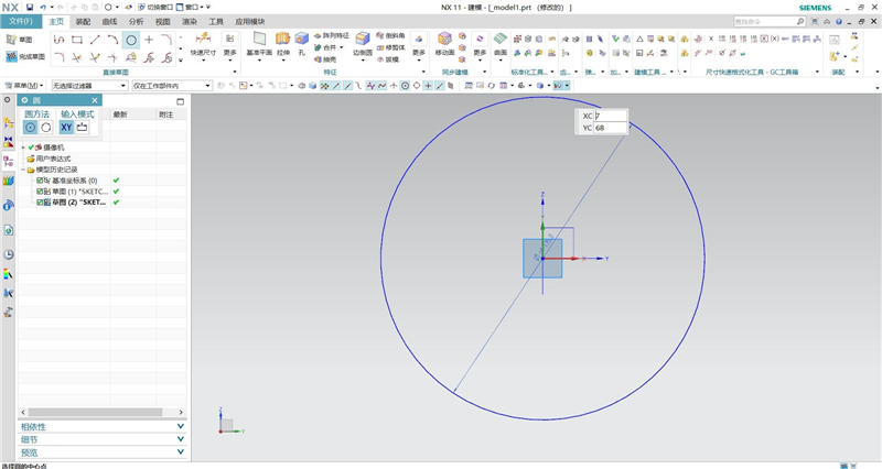
Draw a circle which diameter is 135mm and take the origin of the coordinate as a dot, on the Z-Y plane.
Use the scan command. Then the solid is obtained by taking the rectangular box as the section and the circle as the guide line.
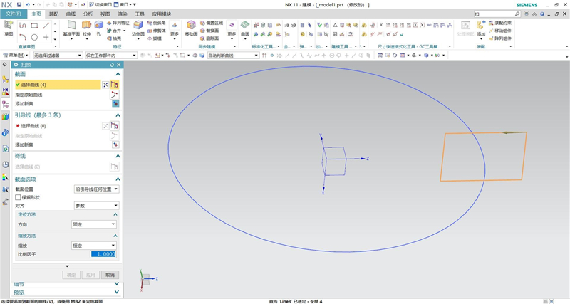
Under the scan command, open the section option and set it as shown in the following figures.
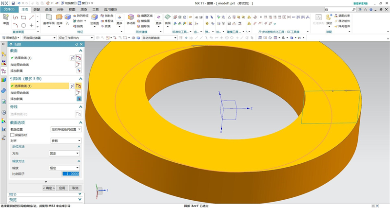
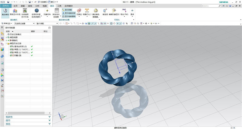
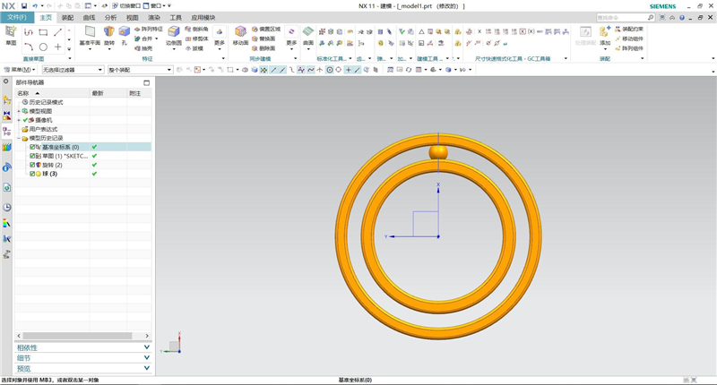
The mobius ring is shown in the following figures.
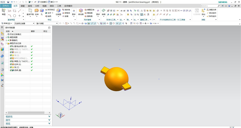
② Antifriction bearing
Draw a sketch, Select X-Z plane. Then draw the picture as follows:
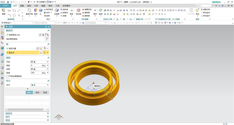
Use the rotary tool and draw the following figure with the sketch as the section curve, the z-axis as the axis of rotation, and the center of rotation as (0,0,0).
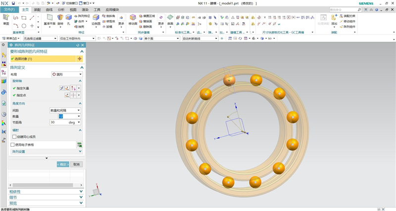
Draw a sphere is created with the center point (13,0,0) as the center and a diameter of 3mm.
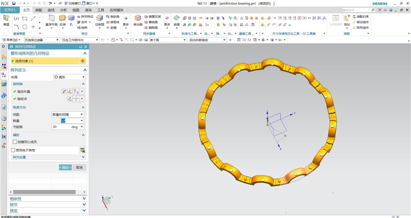
Array the sphere with the rotation point (0,0,0), as shown.
Draw a sketch, Select X-Y plane. Then draw the picture as follows:
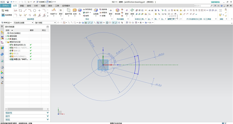
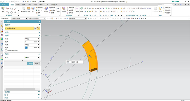
Use the drawing tool, take the sketch as the section curve, and the drawing height is 0.5mm.
Draw a sphere is created with the center point (13,0,0) as the center and a diameter of 4.6mm. Then sum the sphere and the arc.
Draw a sphere is created with the center point (13,0,0) as the center and a diameter of 3.6mm. Then demand the sphere and the body.
Draw a cylinder with the center point (13,0,0) as the bottom center, a diameter of 24.8mm, and a height of 10mm. Then demand the cylinder and the body.
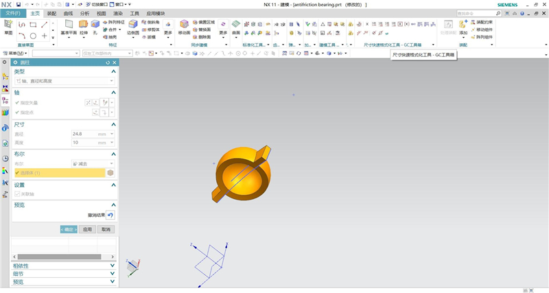
Draw a cylinder with the center point (13,0,0) as the bottom center, a diameter of 27.5mm, and a height of 10mm. Then intersect the cylinder and the body.
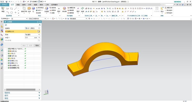
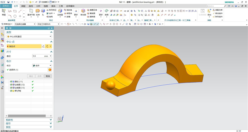
Draw a sphere is created with Center point of curved edge as the center and a diameter of 0.56mm. Then sum the sphere and the arc.
Array the body with the rotation point (0,0,0), as shown.
Taking the horizontal plane as the mirror plane, the mirror feature body.
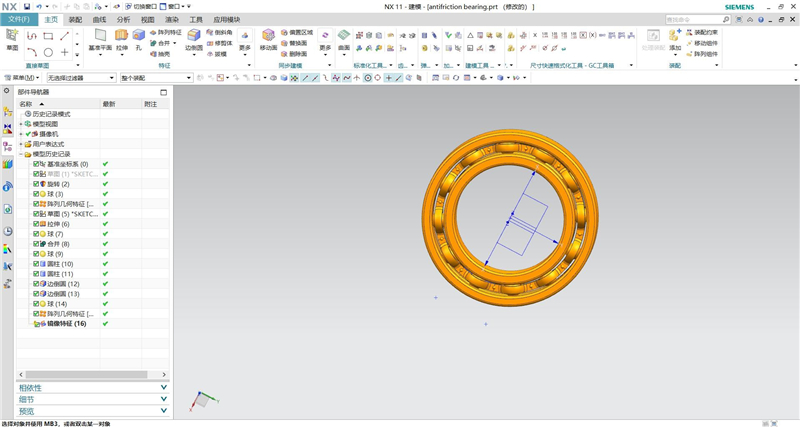
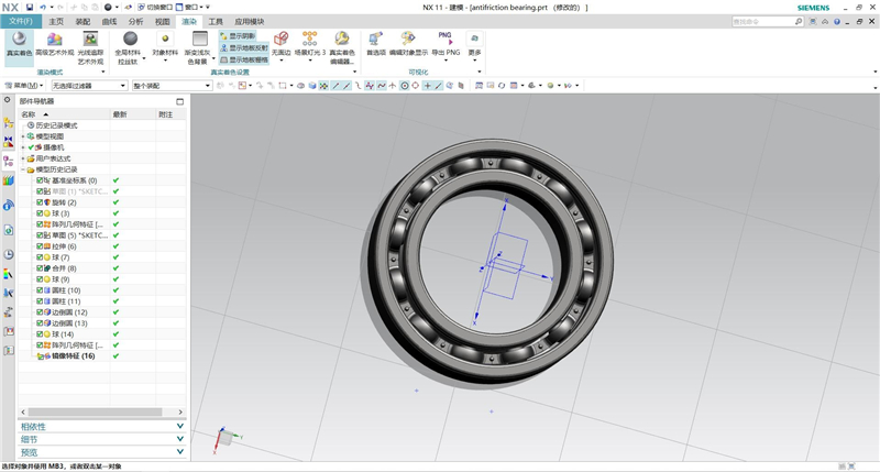
The final result is shown in figure.
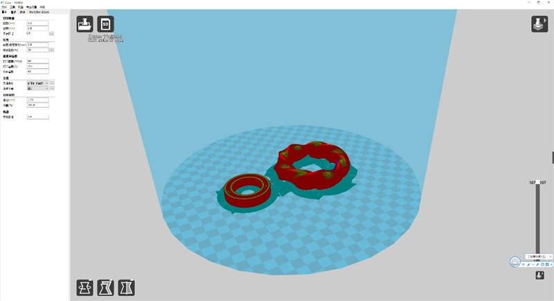
Layer height: 0.2mm, Wall line count:0.8mm, Top layers:0.8mm, Bottom layers:0.8mm, Infill: 20%, Speed: 60mm/s, Nozzle temp: 210℃, Bed temp: 45℃, Material: 1.75mm PLA, Nozzle diameter: 0.4mm, Support type: extend to platform.
In this part of the assignment, I used Qlone ios app for 3D scanning. And, I used JTscan-FS/MS for 3D scanning.
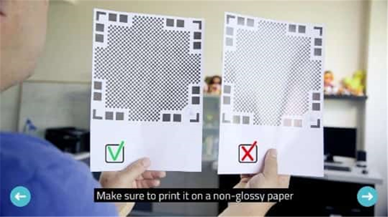
① The workflow of Qlone APP
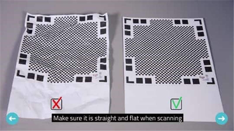
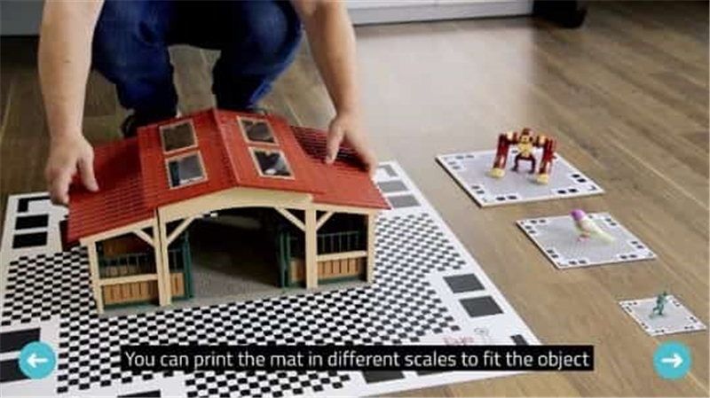
Step1: Get the mat from the app or their website and print it.
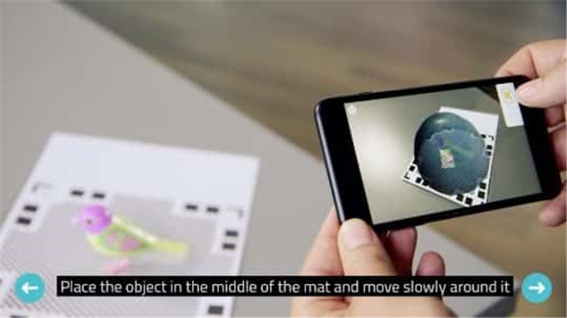
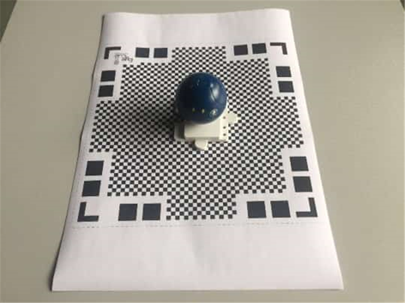
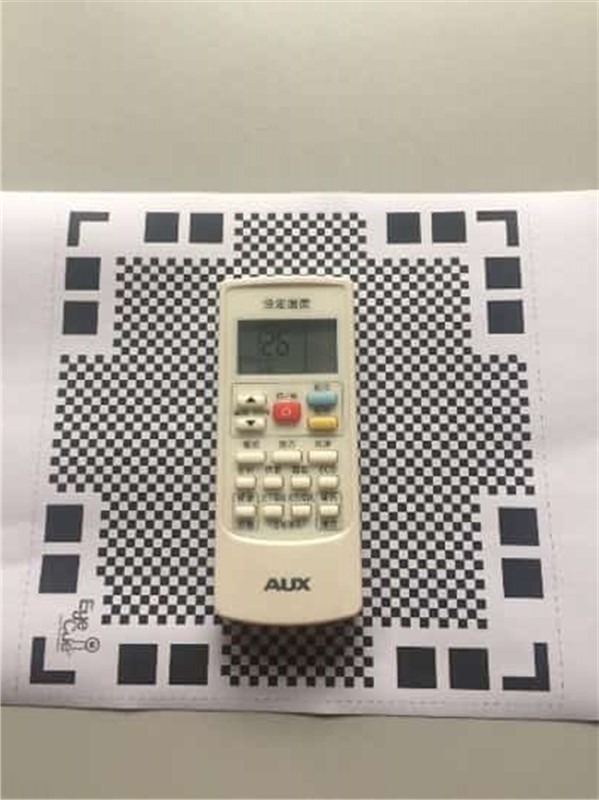
Step2: Place the object in the middle of the mat.
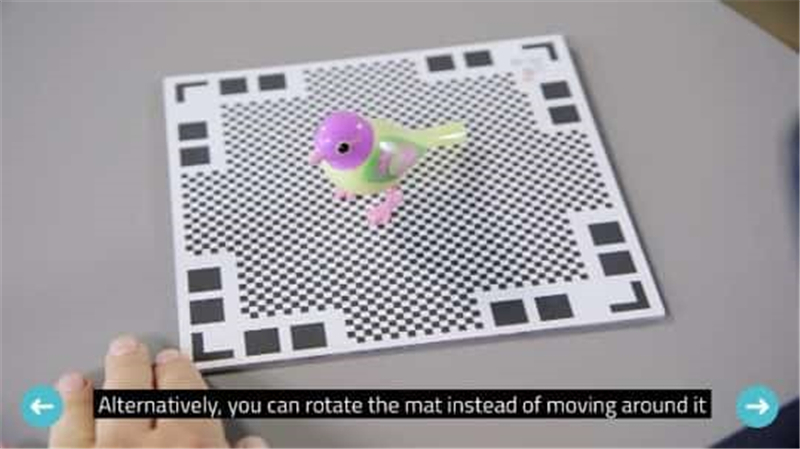
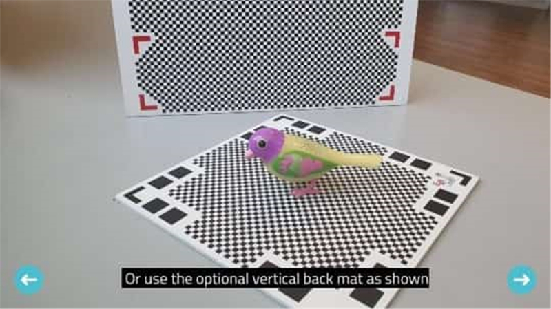
Step3: Move slowly around the object and the AR dome in the app will guide through the scanning process. Also, you can rotate the mat instead of moving around it.
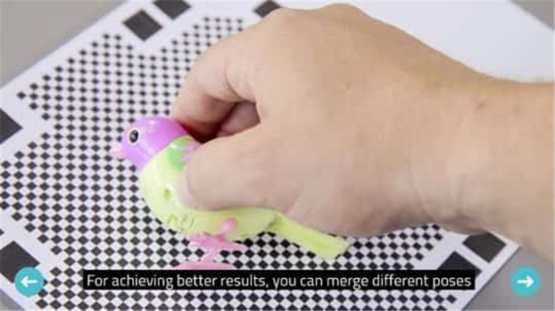
Step4: For achieving better results, you can merge different poses. Or use the optional vertical back mat as shown.
② Test
I scanned a HARO which in cartoon of Gundam and scanned a remote-control panel for air conditioning.
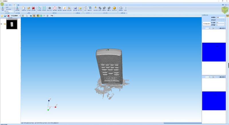
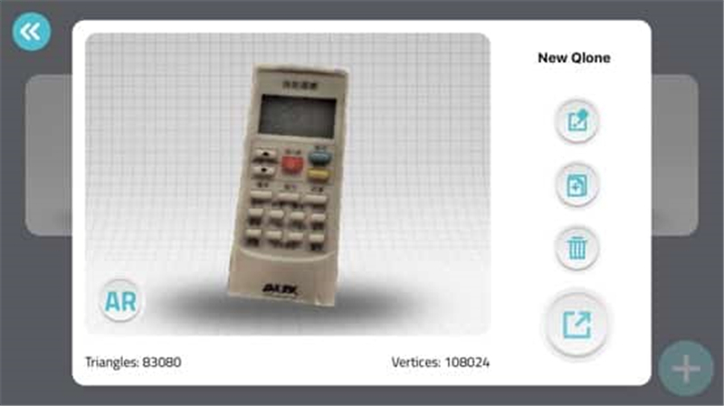
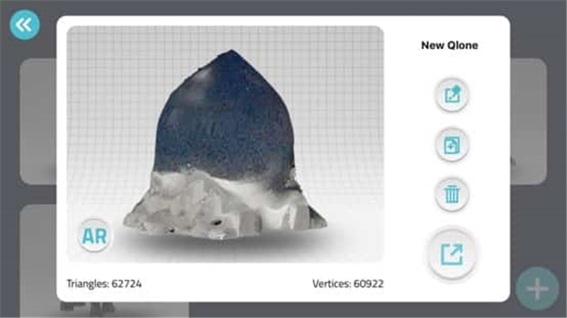
③ result
Because of the software export format not free, so I can only take the screenshots.
① Introduction to 3D scanner
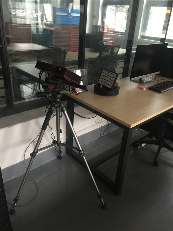
② The workflow of JTscan-FS/MS
Step1: Remove the protective cover from the camera.
Step2: Place the object in the middle of the rotating platform. Note that the object will not be outside of the platform.
Step3: Turn on the power supply of the 3D scanner and turn on the software of SL3DSCAN on the computer.
Step4: Create a new scanning task, and set the options of the scan.
Step5: Click the button of scan. During the scanning process, the scanner digitizes the points on the surface of the object, and then the data points will appear in the main interface.
Step6: It can completely digitize the physical object, through scanning different locations for many times.
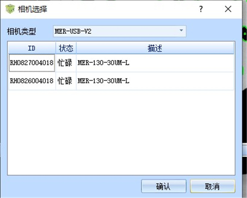
③ Correct the 3D scanner and the turn table
Step1: Choose the camera in the software of 3L3DSCAN and then choose the calibration plate.
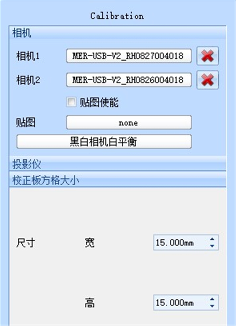
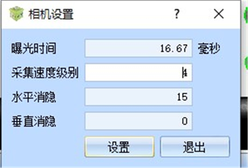
Step2: Set the camera focal length, exposure, brightness and projector focal length.
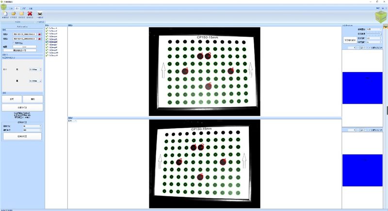
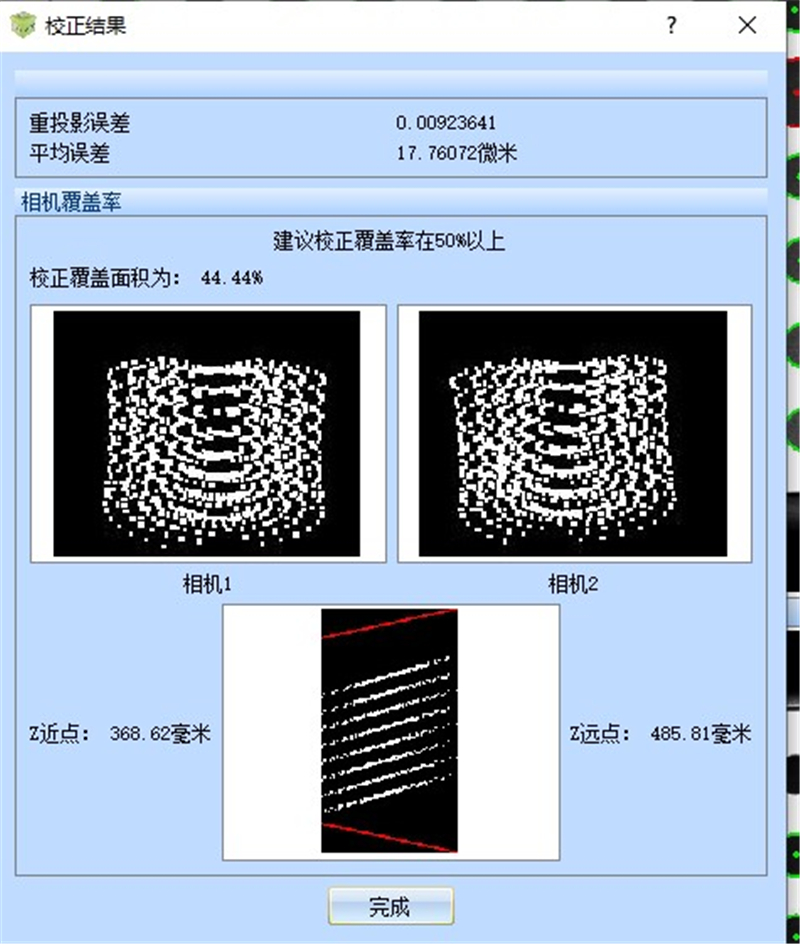
Step3: Correct the 3D scanner and the turn table
④ Scanner