week_04
Electronics production
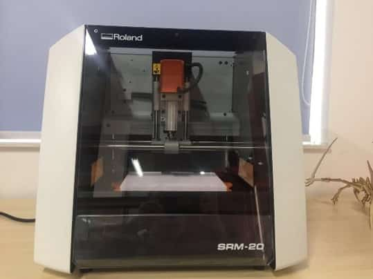
For this week’s group assignment, I had to characterize the specification of my PCB production process on our small CNC milling machine (Roland SRM-20).
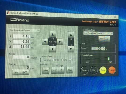
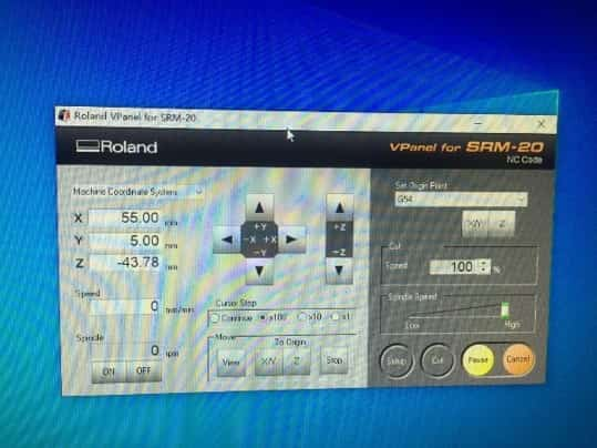
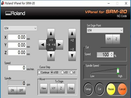
The machine in my lab is Roland SRM-20, The Machine Specs are as follows:
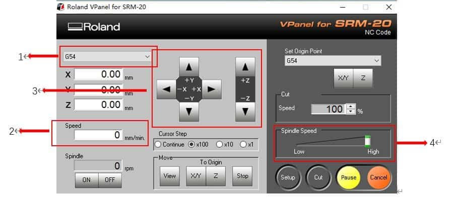
No1. Coordinate system--Selects the coordinate system for the coordinate values to display.1) User Coordinate System: A coordinate system in which the location of the origin point can be freely changed. 2) Machine Coordinate System: A machine-specific coordinate system in which the location of the origin point is fixed. 3) G54 - 59: A workpiece coordinate system in NC code. 4) EXOFS: A coordinate system used with NC code.
No2. Speed--The movement speed of a cutting tool is displayed.
No3. Movement of a cutting tool--A cutting tool is moved. Holding down the buttons performs continuous movement.
No4. Spindle Speed--Adjusts the spindle speed. "Adjusting the Feed Rate and Spindle Speed During Cutting"
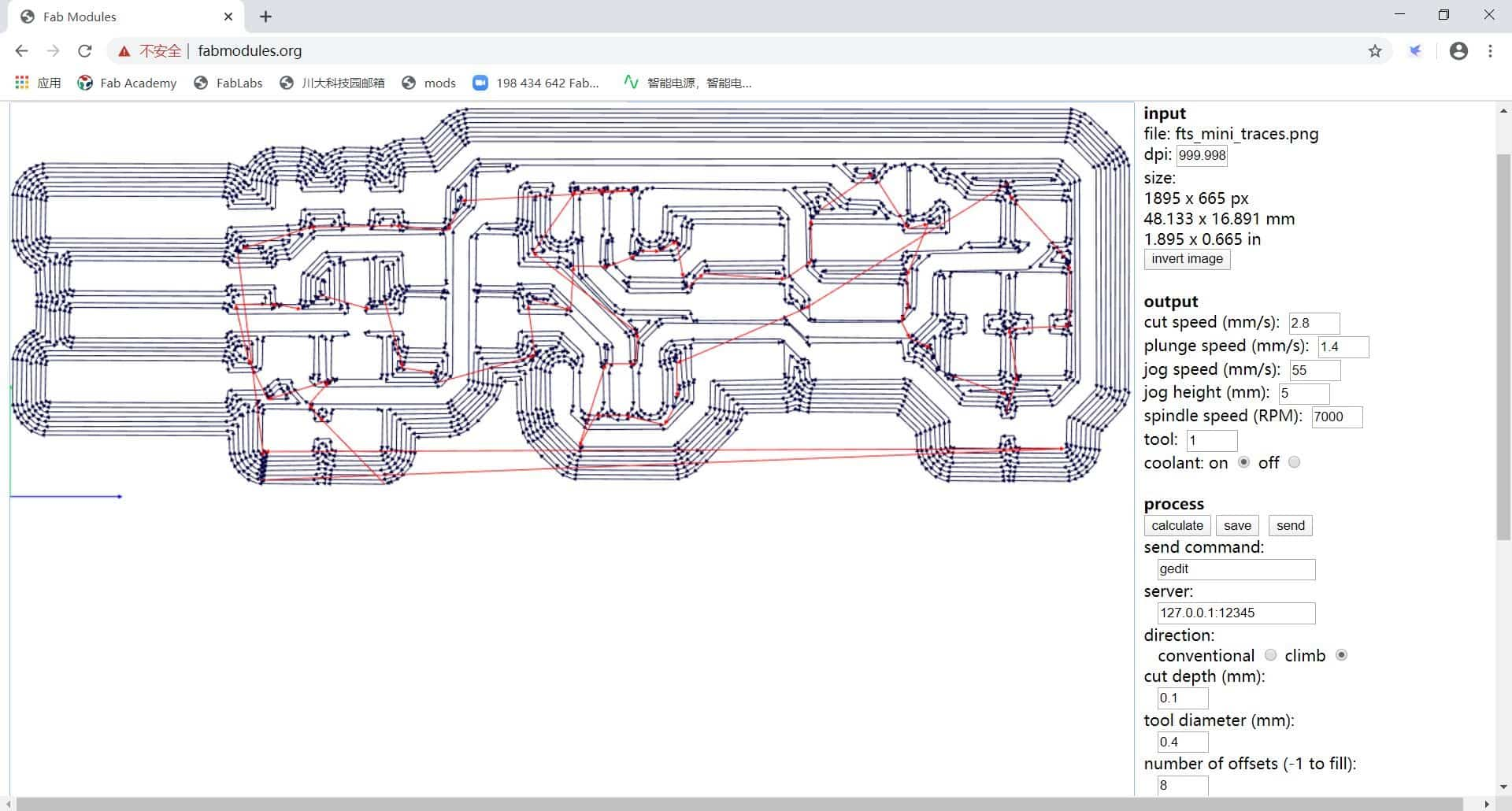
I have learned the tool that help to convert monochrome PNG file into G-code, and also I have learned the software of NX UG. The main requirement is that there should either black or white parts of on the picture. The white parts will be stay, and the black parts will be cut out by the mill. Therefore, it is important to keep the distance between significant enough so that the endmill can go between two white parts.
① Choose select PNG file. I loaded my picture of my mill traces.
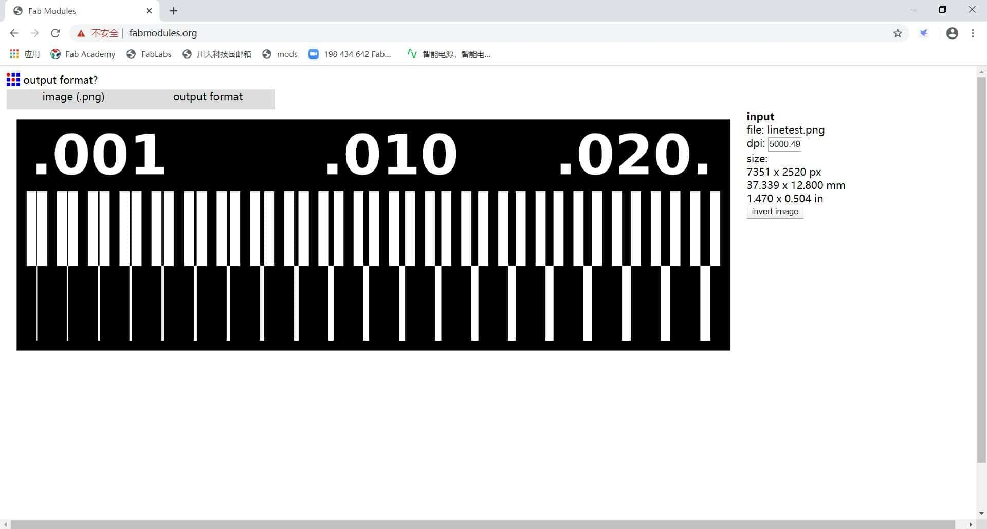
② Choose the output format, as G-codes (.nc). Then I clicked on the third labeled option mill traces 1/64.
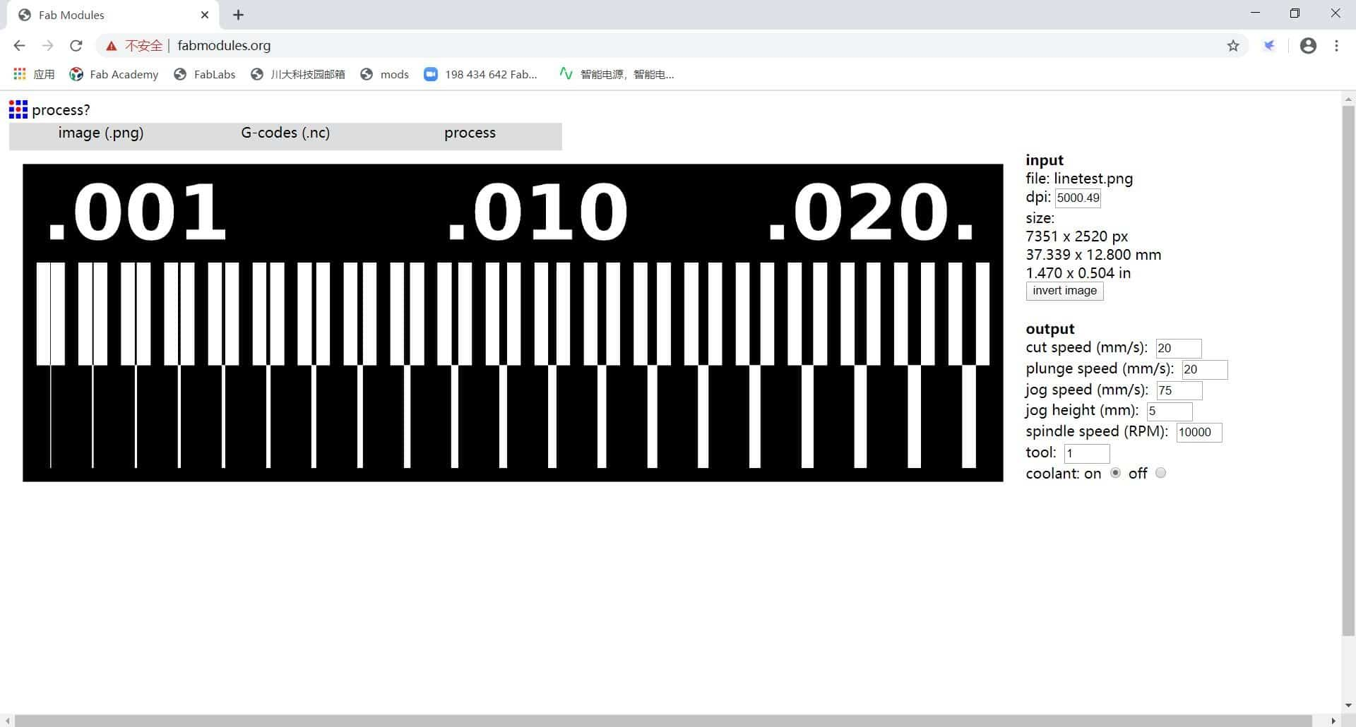
③ Then, I set some of parameters as follow:
Cut speed (mm/s) =2.8mm/s; Plunge speed (mm/s) =1.4mm/s; Jog speed (mm/s) =55mm/s; Jog height (mm) =5(means that the machine will lift the tool 5mm while not cutting); Spindle speed (RPM) =7000; Cut Depth=0.1mm; Offset-overlap=50%; number of offsets=-1. Then I go to click on calculate. This option calculated my toolpath for the machine to raster my trace.
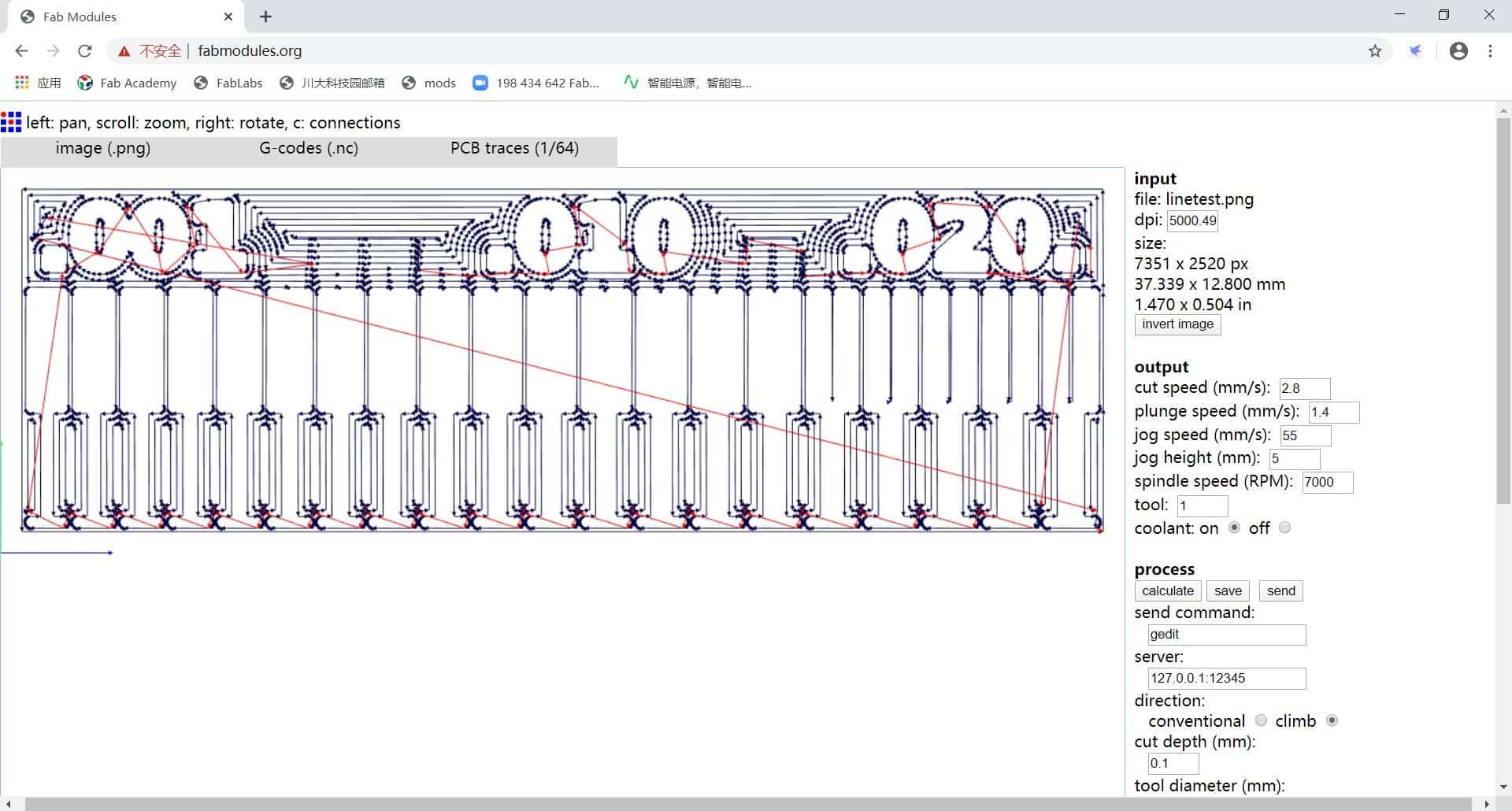
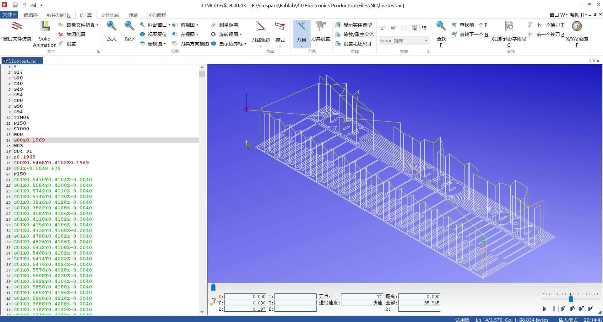
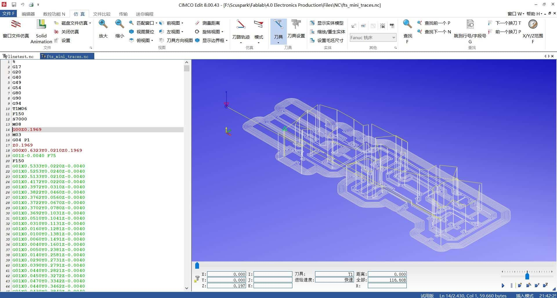
⑤ Finally, The machine is ready now just click send and the machine will start to cut. Then, I used CIMOC to check the program.
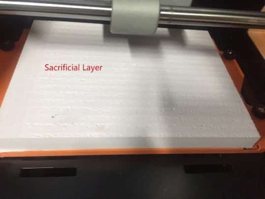
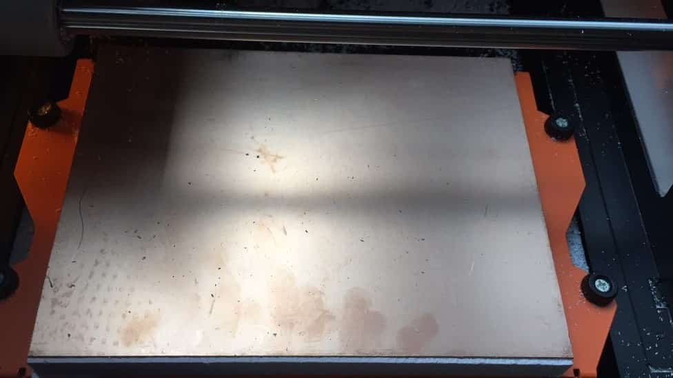
What you put on top of the machine in order not to break the tool. It is located on top of the work plate to protect the tool. Also, the Sacrificial layer needs to be level, otherwise when you are cutting your circuit it won't cut the deepness to the same level. So, I milling the sacrificial layer with a 6mm endmill to ensure the plane level.
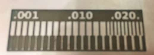
This is the result of the test:
In-system programming (ISP), also called in-circuit serial programming (ICSP), is the ability of some programmable logic devices, microcontrollers, and other embedded devices to be programmed while installed in a complete system, rather than requiring the chip to be programmed prior to installing it into the system.
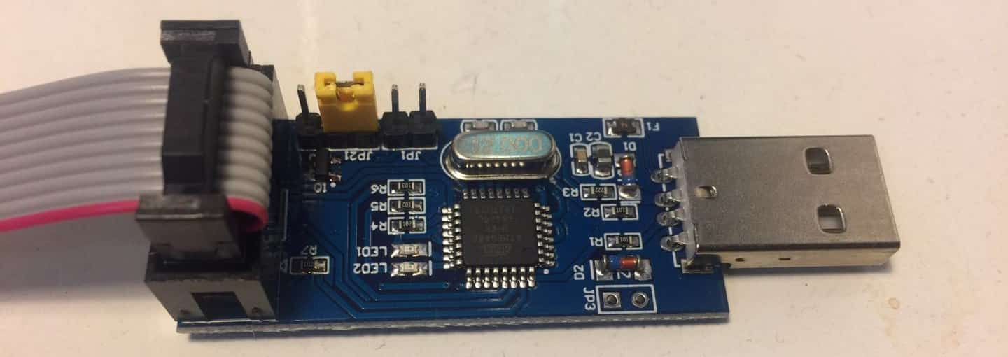
The FabISP is an in-system programmer for AVR microcontrollers, designed for production within a FabLab. That is, it allows you to program the microcontrollers on other boards you make, using nothing but a USB cable and 6-pin IDC to 6-pin IDC cable. It's based on the USBtiny and V-USB firmwares, which allow the ATtiny44 to perform USB communication in software. Programming can be done through avrdude.
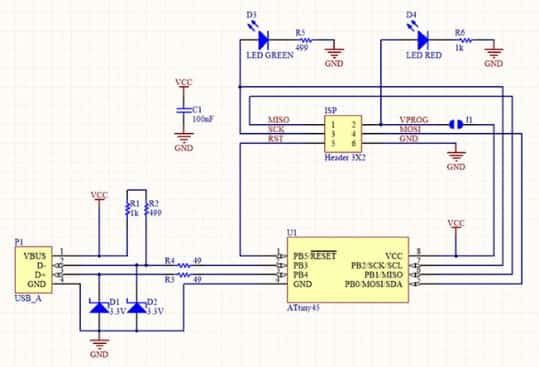
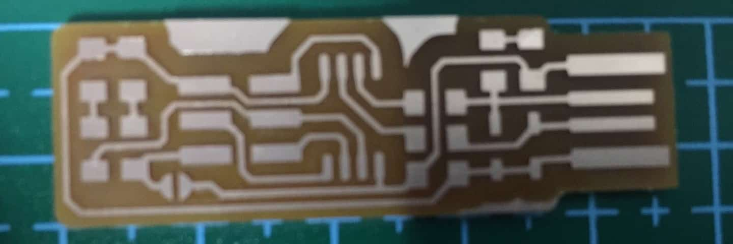
The schematic and PCB board are:
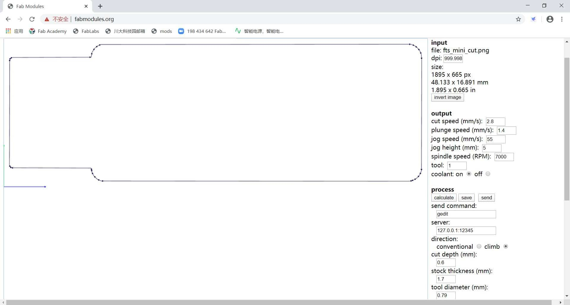
① ① Used Fab Modules. First, I download the traces image from Website. Then I imported the traces image, the image is in PNG format, with only black and white lines. I Choose the output format, as roland mill. Then, I choose the process, which is milling the traces. I finally press calculate to generate the toolpath and save the toolpath code.
② Then, I will import the outline image to Fab Modules. I repeat the process as above but this time I choose the outline process instead of the traces process.
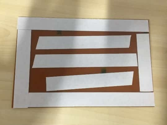
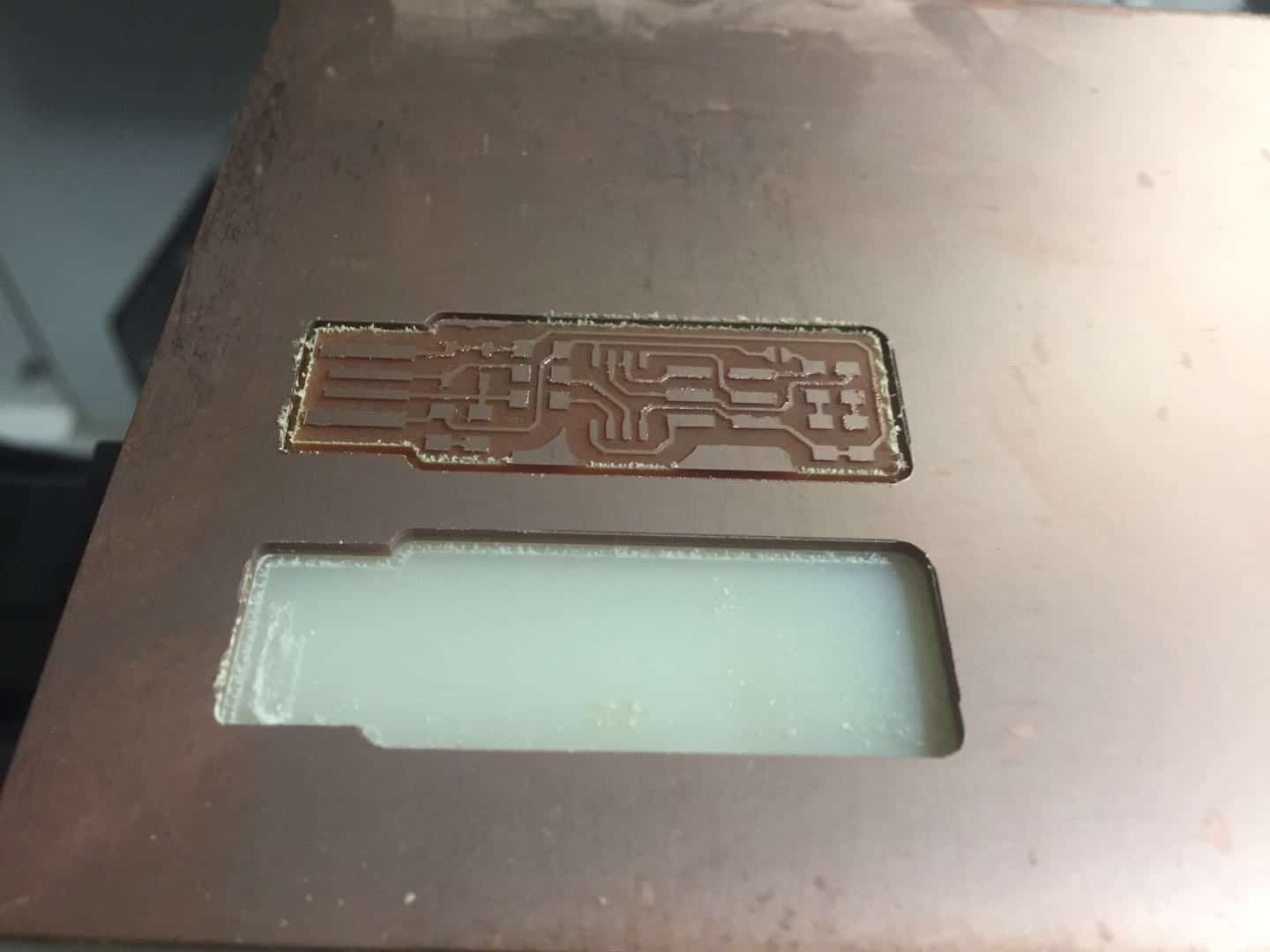
① I fix the PCB to the milling machine plate use double side tape. I need to make sure that tape layer is smooth with no wrinkles. The surface of the material must be parallel to the x and y-axis of the machine.
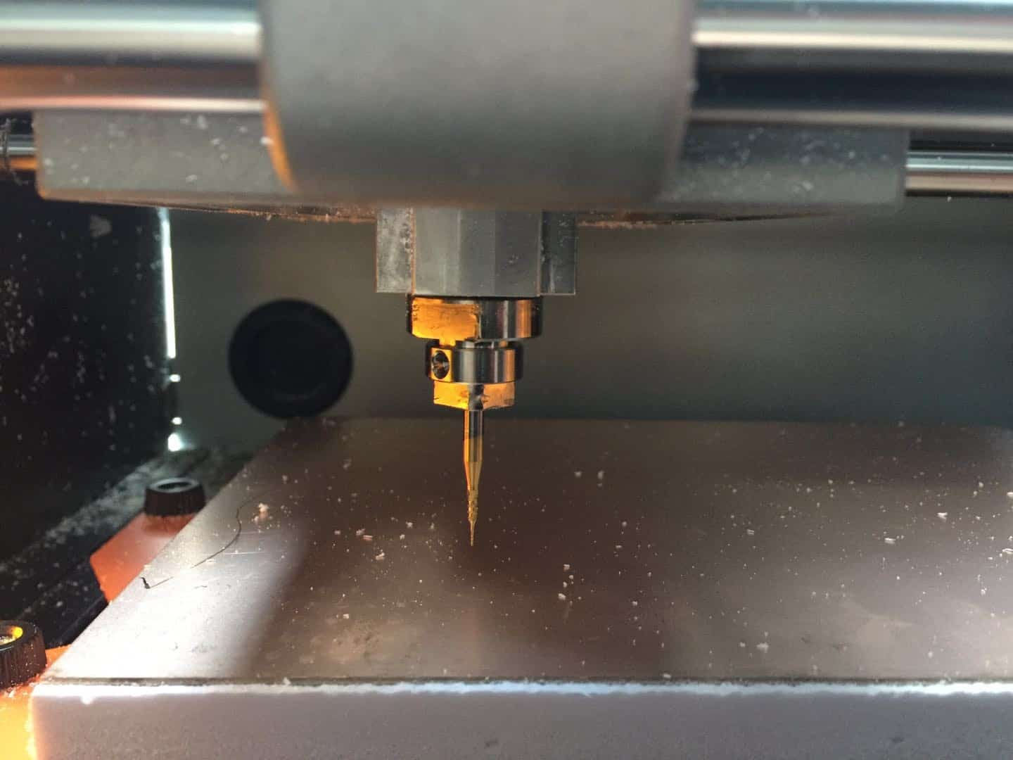
② I used a 0.4mm endmill to engrave the traces on the material surface and a 0.8mm endmill to cut through the material.

③ First, I need measure the workpiece coordinate system, that is setting the origin of X axial, Y axial and Z axial(the method of try cutting).
④④ Click on Cut to output the file to the miller. You are all set. When the milling was finish, I removed the material from the material bed slowly with a palette knife. Then remove the double-sided tape on the back of the material. Then, clean the copper face of the board with alcohol to retrieve traces of grease.
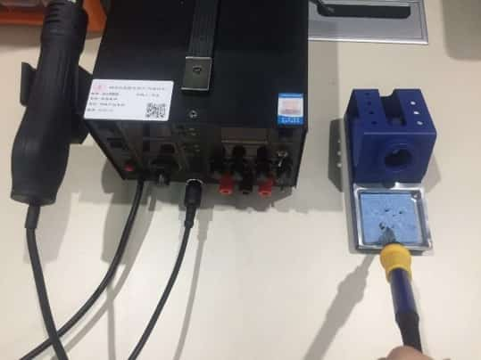
① Wet the sponge for cleaning the tip of the heater.
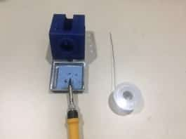
② Cut the a piece of solder from the roll to work better with it. My solder should not be thick particularly for this project, because it is a small component.
③ Start with soldering the components from starting from the middle of the board (ATtiny45), then I go to the next near to the board’s exterior. I must note the components that installed in the correct orientation:
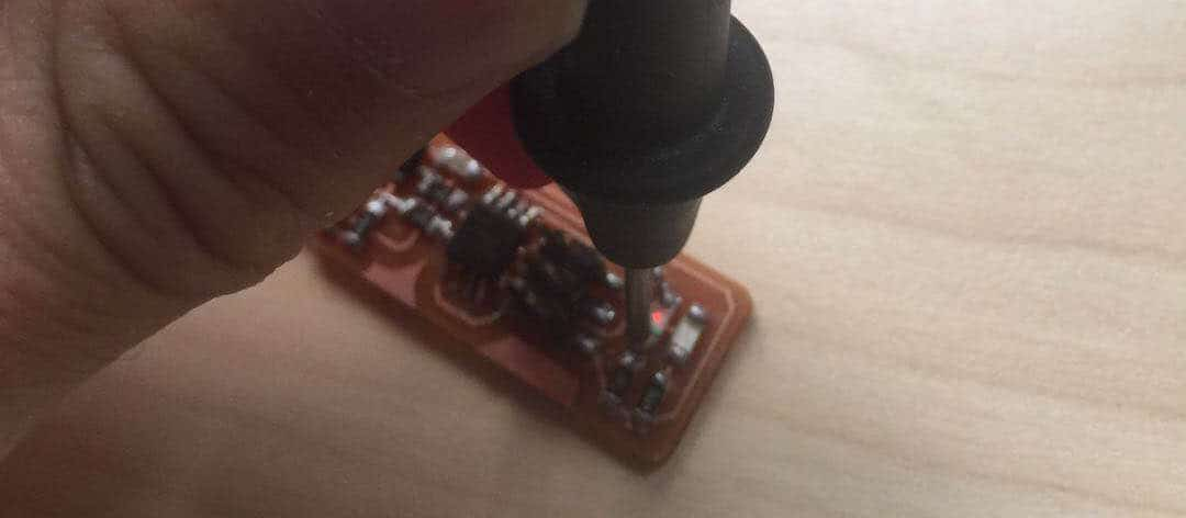
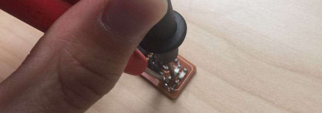
When I welding, I need to notice that don’t touch the solder directly to the tip of the iron. I need the joint to be hot enough to melt the solder when it’s touched otherwise it will form a bad connection. And also, I must note the components that installed in the correct orientation.
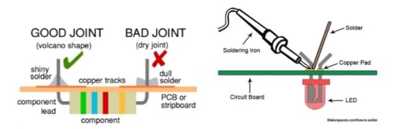
In the previous several welding, I did not grasp the welding essentials, so some joints too much or too little solder.

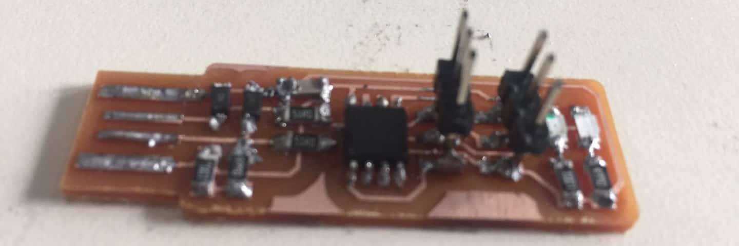
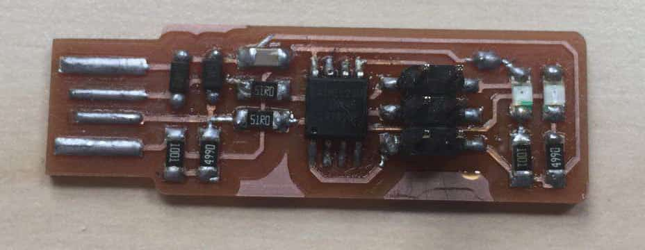
This is the product that failed before I mastered the welding skills. Then I tried to make second board, but I found that the green LED is not bright. So I use the multimeter, I found that I took long time to weld and the green LED was damaged. So I replaced the LED replaced. Just in case ,I made third board.
④ Final Product
I followed the routine on Brian’s page.
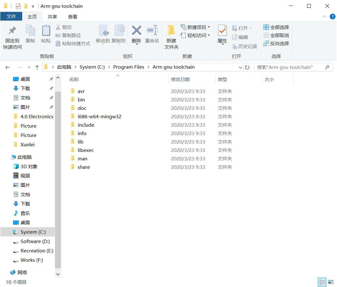
⑴ Install the Atmel AVR toolchain.
Download the Atmel AVR toolchain and extract the files in c:\program files.
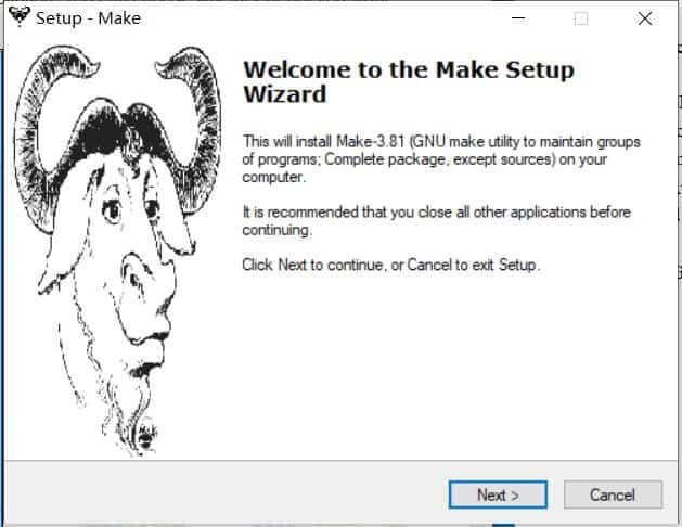
⑵ Install GNU Make.
Download Gnu Make and launch the installer. Accept the default location for the installation.
⑶ Install abrdude.
Unzip the archive, and copy the archive inside to C:\Program Files.

⑷ Update my PATH.
Now we need to tell Windows where to locate all of the tools you've just installed when you type their names on the command line. Go to the Start menu and open the Control Panel, then go to System. From the left pane, choose "Advanced System Settings". Under the Advanced tab, click the "Environment Variables" button.
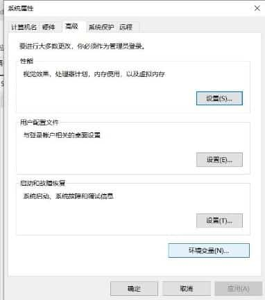
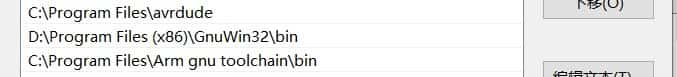
The three values to add are:
C:\Program Files\Arm gnu toolchain\bin
D:\Program Files (x86) \GnuWin32\bin
C:\Program Files\avrdude
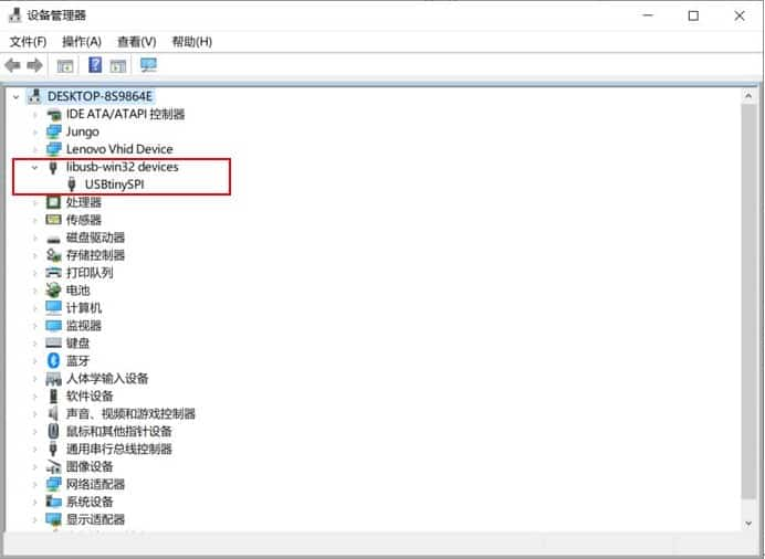
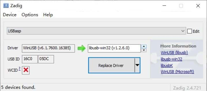
⑸ Install Drivers for my Programmer
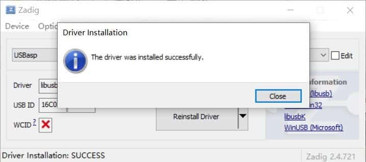
Download Zadig and launch it. Plug in your programmer, and select the "USBtinySPI" device in the list. (If it doesn't show up, go to the Options menu and click "List All Devices". The driver you want to install (to the right of the green arrow) is either libusb-win32 or libusb0. Click the "Install Driver" button. You should only have to do this once.
⑹ Sanity Check
Everything is now installed. Let's check that it all works.
Go to the start menu and search for "Git Bash" and start it. When you see instructions telling you to open your terminal in other tutorials, this is the terminal window you should use.
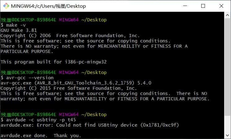
Check to make sure that the commands we installed work okay.
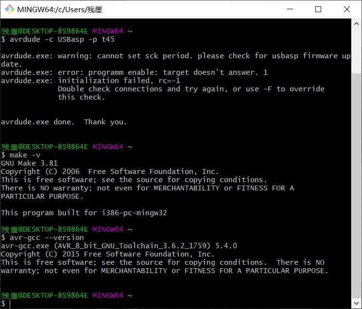
The first time I found an error which is could not find USBtiny device (0x1781/0xc9f). Then I search this in internet. I found that I may try write this “avrdude -c USBasp -p t45”. Because the name of my programming unit is USBasp.
⑺ Next step is to download the firmware file. Unzip and extract the files.
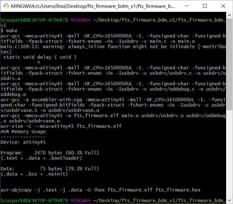
⑻ Open your terminal program and navigate to the directory(firmware) and run make command. It will generate a hex file (firmware_fts.hex).
⑼ Open the hex file and change the name of the programmer from usbtiny to avrispmkii.
⑽ Connect the board to the USB jack and programmer to the ISP header of the board. Make sure the orientation is right (MISO –> MISO).
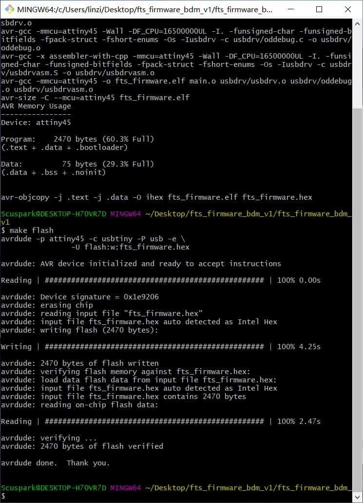
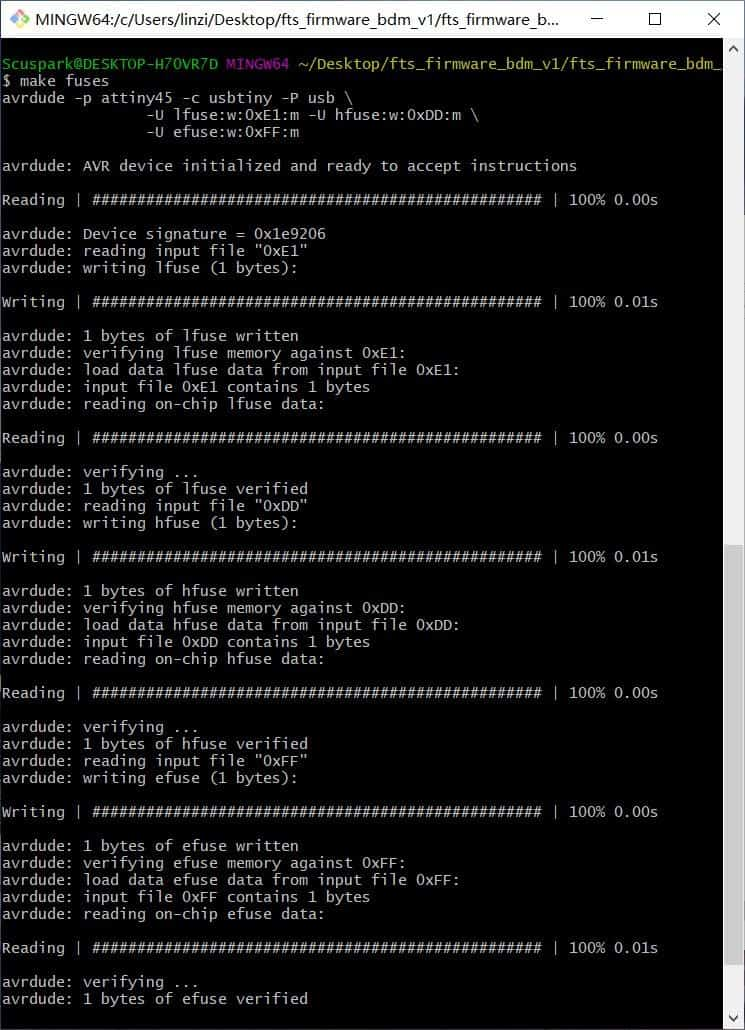
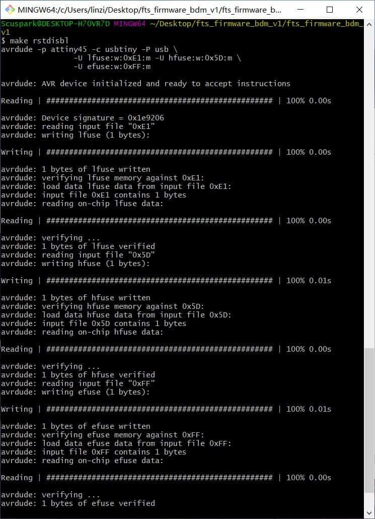
⑾ Run make flash. This will erase the target chip, and program its flash memory with the contents of the .hex file you built before. Then Run the make fuses command. This will set up all of the fuses except the one that disables the reset pin. Last, Run make rstdisbl. This does the same thing as the make fuses command, but this time it’s going to include that reset disable bit as well.
⑿ Then, check that if the fabIsp is being detected in your windows or not. For that, connect the fabISP to your usbport and open device manager. Scan for hardware changes and look for “libusb-win32 devices”, under this you will see “USBtinySPI”. If it’s there, congrats, your programmer is ready to program other microcontrollers.