week_03
Computer-controlled Cutting
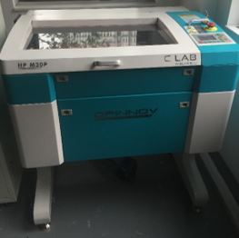
I started with the group assignment to characterize the laser cutter. At C-fablab in Sichuan university, I choose to use the LaserWork V8 which made by Dpinnov Co. Limited. It is a 610*320mm 30W machine.
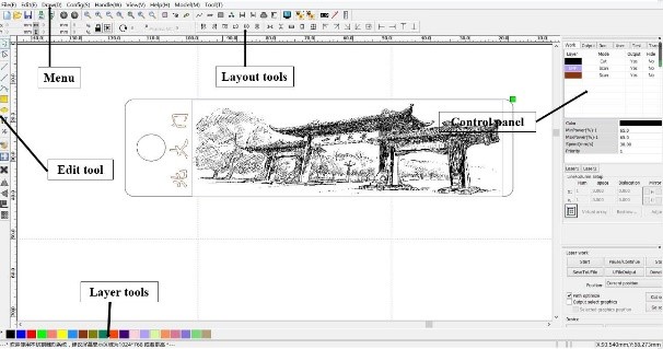
The assignments are run from a computer next to it, through RDWorksV8, USB flash disk and controller.The software is basically used for importing files and assigning colors and layers. This step is important specially if you are going to work with more than one work operation.
Laser cutting machines work with three parameters: laser intensity, laser-head movement speed, and laser frequency.
According to the desired results, the machine setting could be varied freely. The main effect on laser work results is Laser intensity and laser-head movement speed. The reasonable rule is:
Low Intensity + High Speed = marking
High Intensity + Low Speed = cutting
Setp1: Start the power supply of machine, then wait for the equipment self-check completed. The equipment is on standby, when the on-board display screen enters the control information main page.
Setp2: Edit the graphics data on the computer and send the program to the device.
Setp3: Position the materials on the cutting bed and accurate positioning.
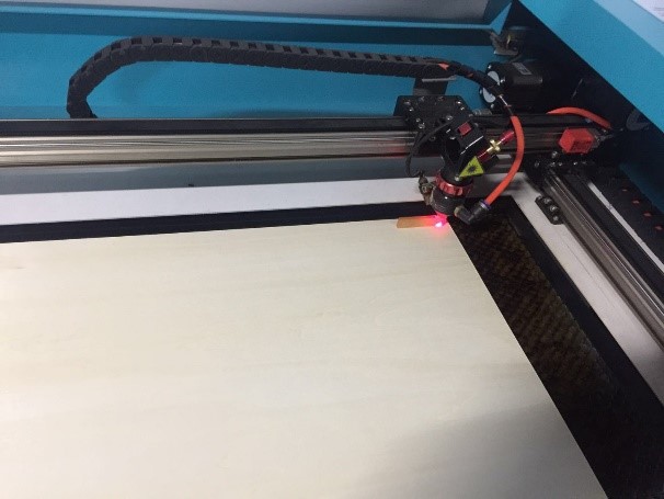
Setp4: Focus the laser using the manual focusing rod.
Setp5: Start the exhaust fan and confirm that there is a gas flow on the honeycomb platform.
Setp6: Close the door of the equipment and confirm that “protection start” does not appear on the control panel.
Setp7: The above parts have been completed without error, and finally confirm the data information is correct.
Setp8: Press "start" on the control panel to start processing.
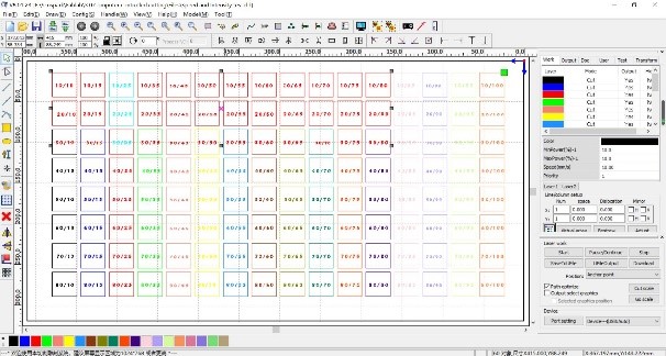
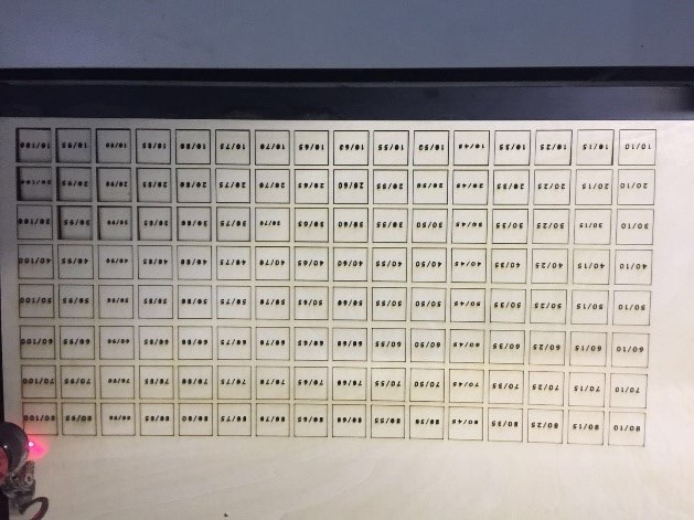
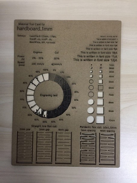
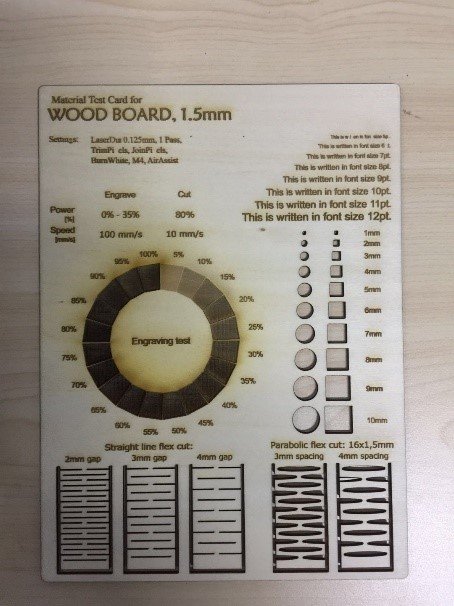
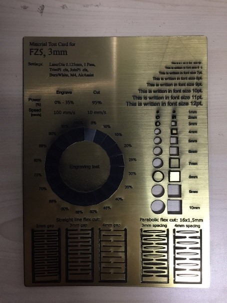
Speed and Intensity test
① Process of the test
In this test idea was to test out the speed and power combination for our laser. Key output was to check at what speed and power the material can be cut. So we cut out a grid of squares with each square cut at varying speed (10 to 800 mm/sec) and intensity (10 to 100 percent) ranges.
The tests of kerf
① What does kerf mean?
The laser burns away a portion of material when it cuts through. This is known as the laser kerf and ranges from 0.08mm – 1mm depending on the material type and other conditional factors.
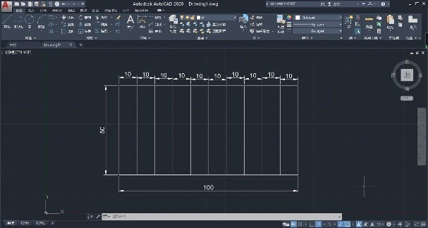
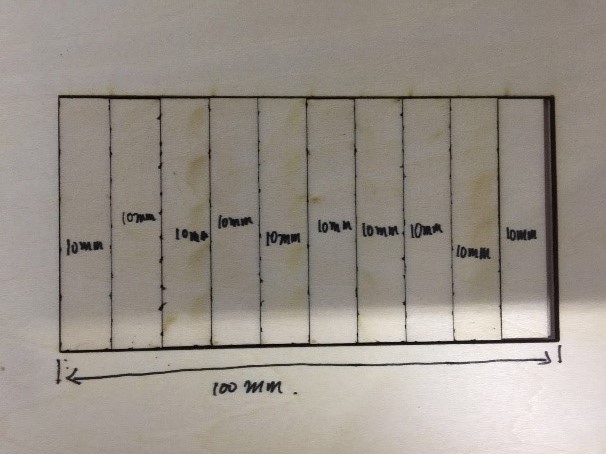
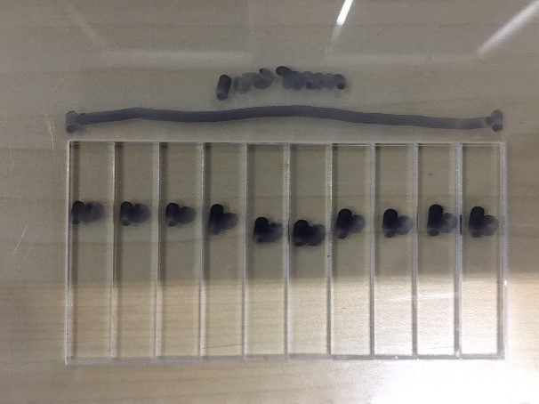
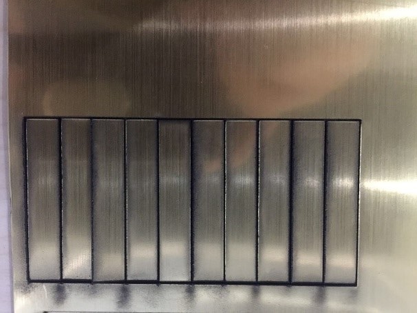
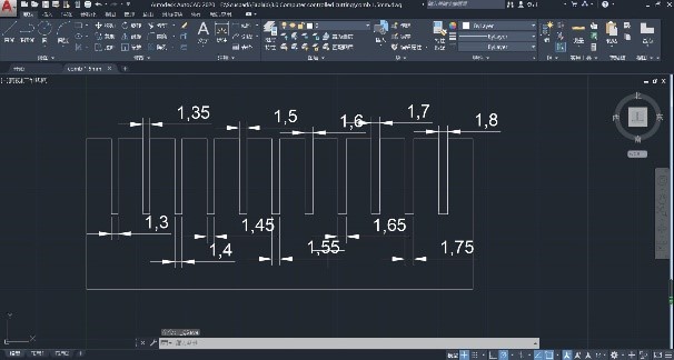
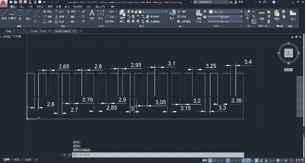
② Process of the test
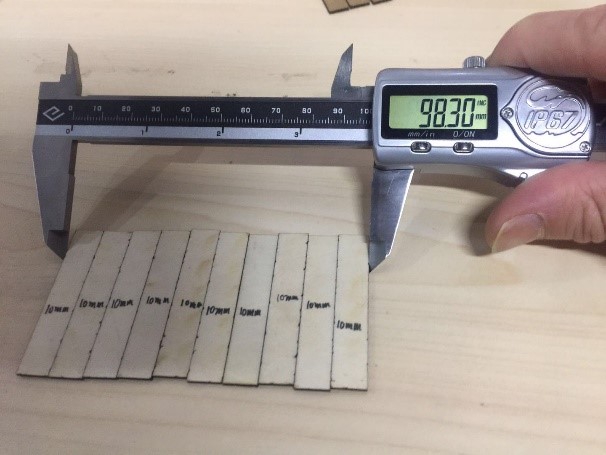
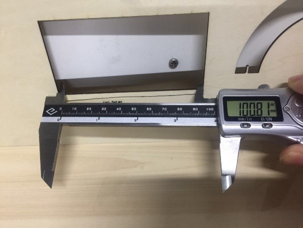
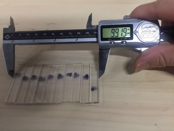
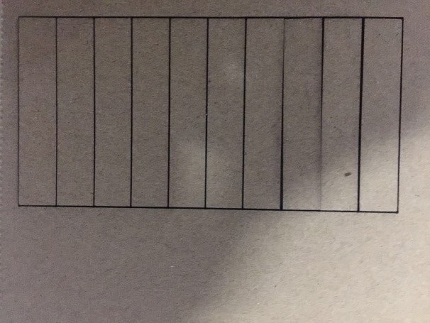
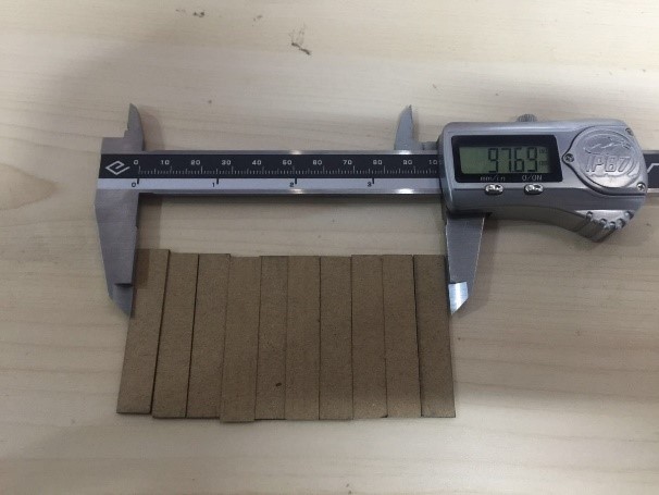
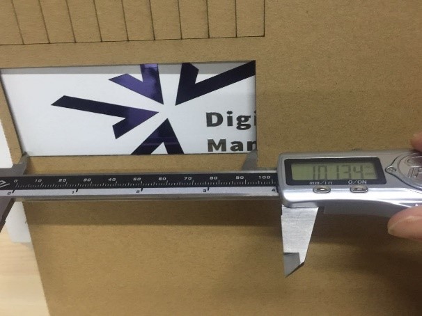
I used the template for all materials which consists of a square with 11 cuts inside, to calculate the kerf I used the formula of deducting the width of the stacked cut bars (A) from the interior width of the square they were taken from (B). So I had 11 cuts the equation would be: kerf=(A-B)/11.
③ Result of test
The kerf calculation and result for each material below:
A. The Tilia plana 1.5mm: kerf=(A-B)/1= (100.81-98.30)/11=0.228mm
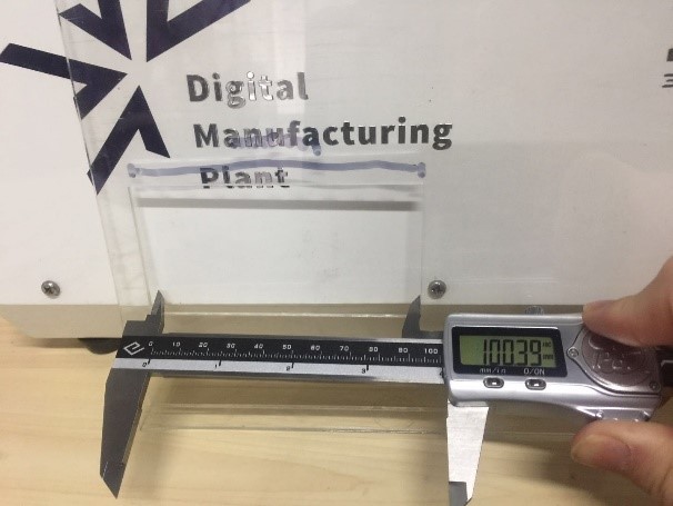
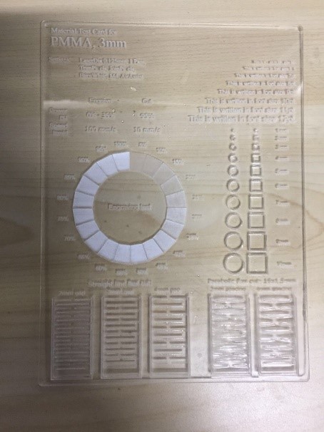
B. The acrylic plate 3mm: kerf=(A-B)/1= (100.39-99.19)/11=0.109mm
C. MDF 3mm: kerf=(A-B)/1= (103.15-100.83)/11=0.211mm

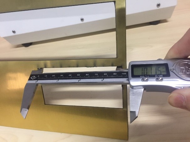
D. bicolor board 3mm: kerf=(A-B)/1= (101.34-97.69)/11=0.332mm
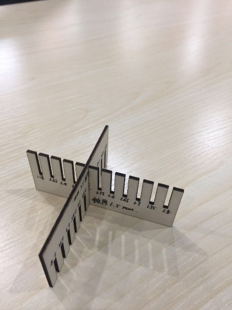
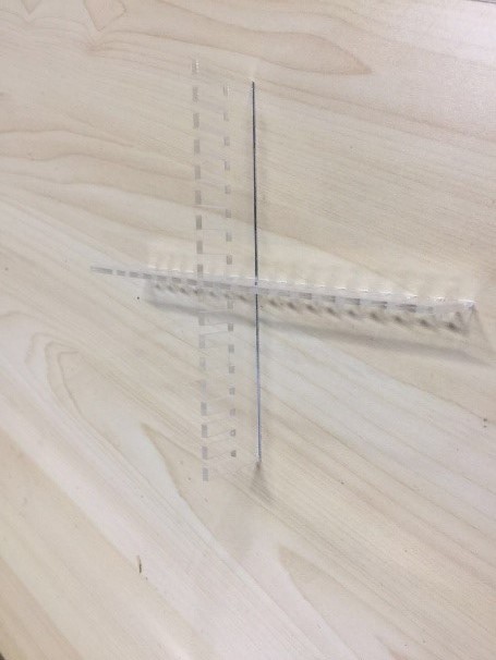
The tests of parametric press-fit construction kit
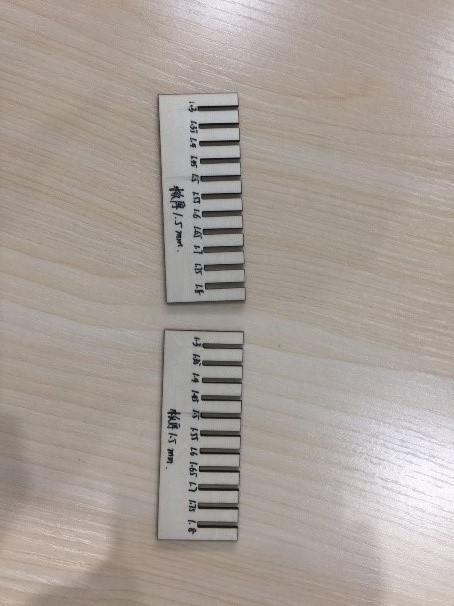
A comb with different teeth sizes was also designed as part of the laser cut preparations to check which fitting will be the most suitable for the specific material. So I decided to design the comb on different materials. One comb was made for matboard with a thickness of 3 mm and the other was comb created for Tilia plana with a thickness of 1.5 mm.
① Design
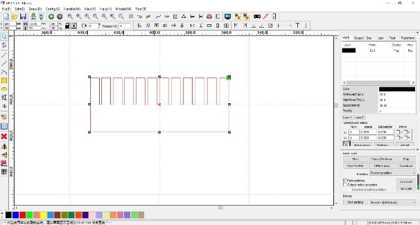
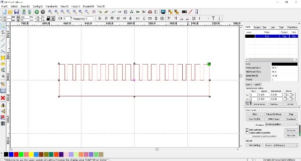
② Software of RDWorksV8
③ Cutting
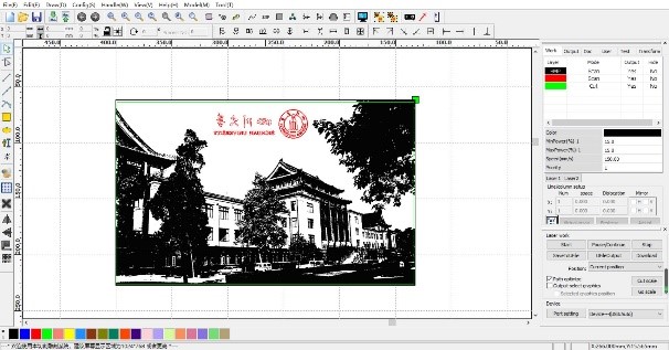
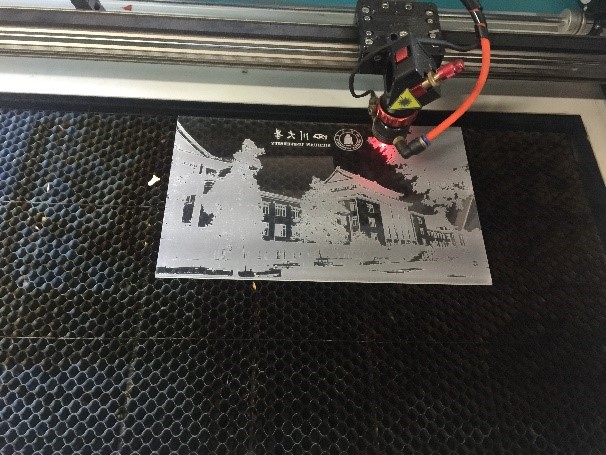
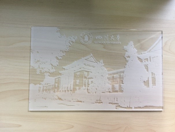
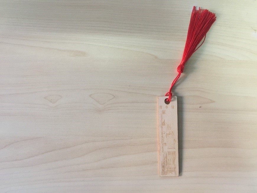
The tests of Etching
① Design
First of all, download picture Which describe the administrative building and the school badge of Sichuan University from the Internet. Then use the software of photoshop to edit photo. In the end of all, edit program of the laser cutter.
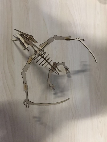
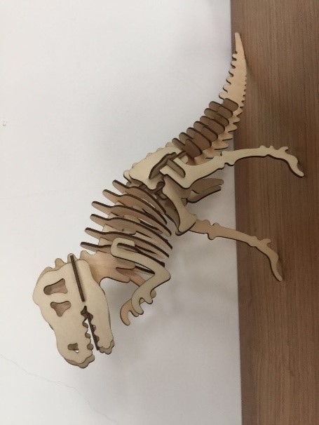
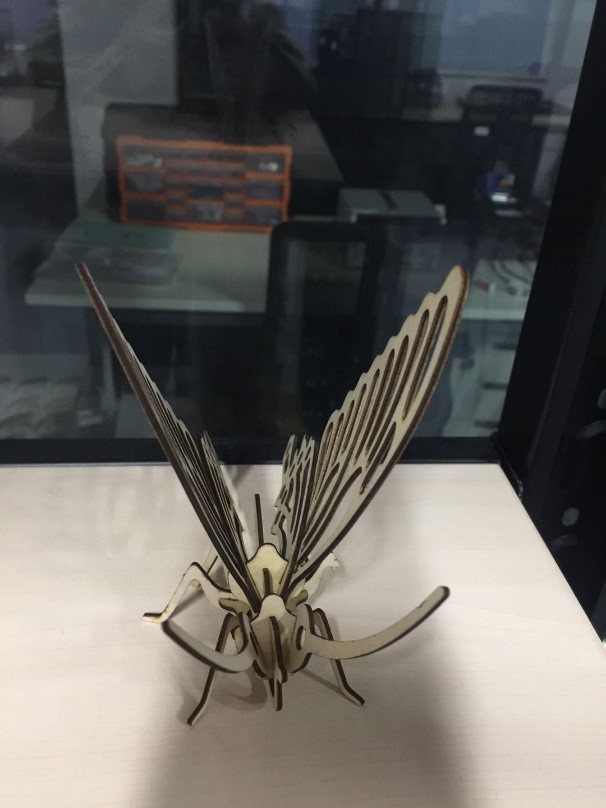
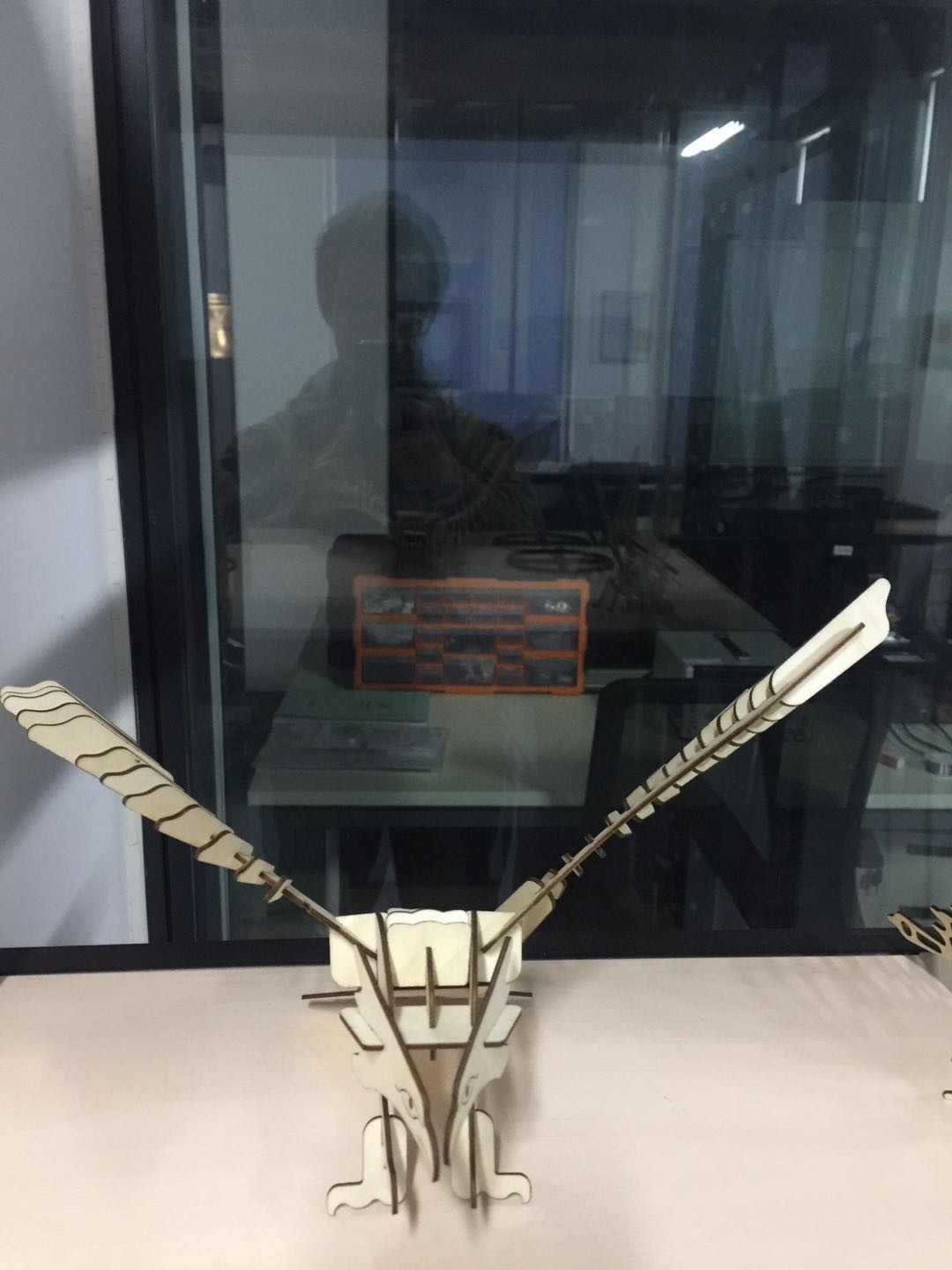
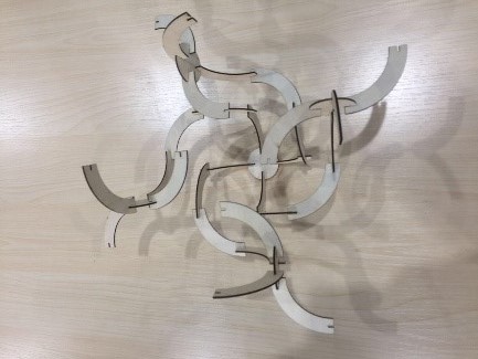
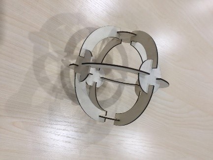
Comprehensive Test
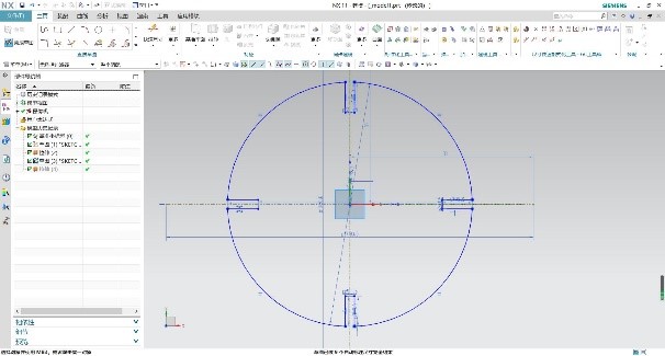
For designing this kit, I used NX UG, which I learned in college and practiced in the previous week.
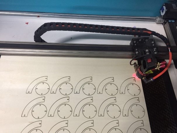
① Draw connectors sketch using circle, arc and line tools.
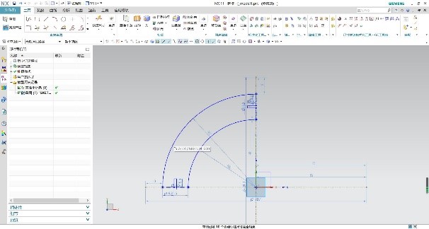
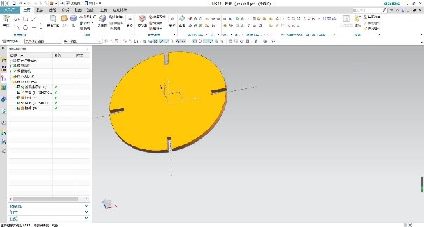
② Stretch to the thickness of the material.
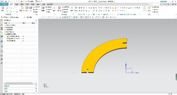
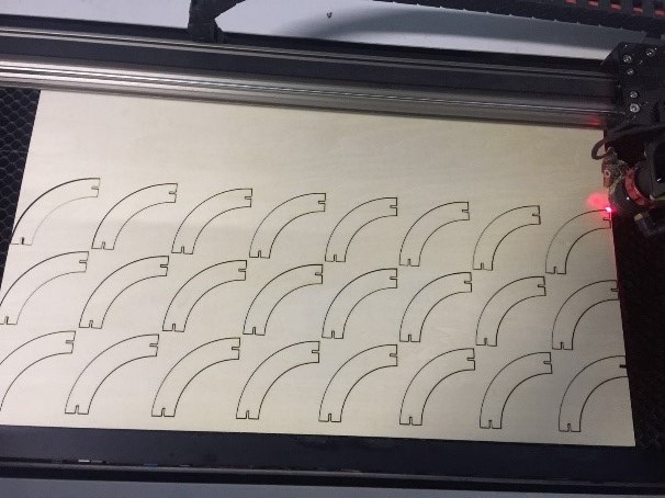
③ Draw a sketch of the main part. Like this, I also selected circle, arc and line tools. Then stretch it.
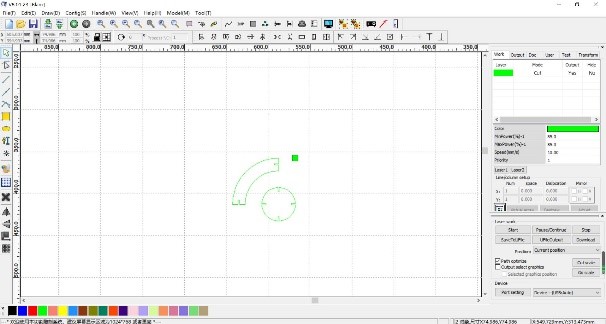
① Download RD works software for setting speed, power and cutting modes.
② Import you dxf files in the RD works.
③ Copy the required no. of parts and align them to minimize the waste.
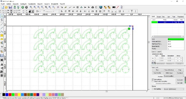
④ Open layer settings, and feed the settings. I used 30mm/sec speed and 65% laser power for cutting the 1.5mm Tilia plana. Select cut as the processing mode.
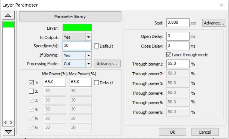
⑤ Connect the machine to the laptop using the USB wire.
⑥ Set the origin.
⑦ Check the cutting parameter by clicking “Go scale” option.
⑧ Click on “Start”.
At C-fablab in Sichuan university, I choose to use the Puma III. It is a 70*719mm machine.
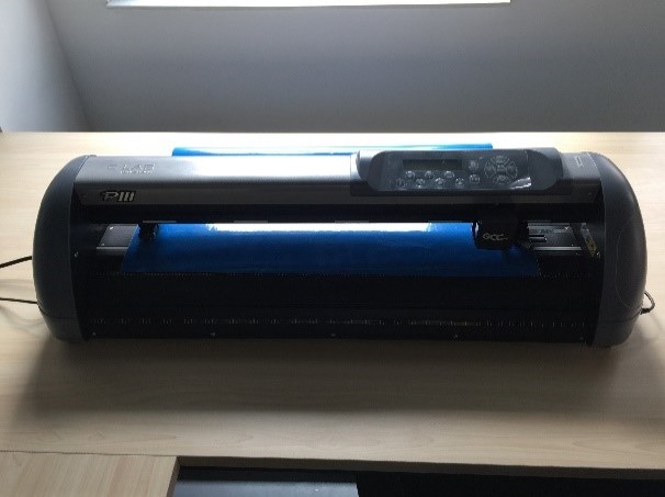
① How it works?
As a general idea, vinyl cutting machines work by cutting materials with a rotatory blade controlled by computer in 2 dimensions (width and height). X and Y are the blade movement limitation axes.
② Main parameters
Vinyl cutting machines work with 2 parameters: speed, and strength. According to the desired results, the machine settings could be varied freely. There is one basic rule to be considered to think the result of the design on the material. The reasonable rule is:
Simple designs = High (Speed + Strength)
Complex designs = Low (Speed + Strength)
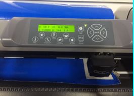
Setp1: Start the power supply of machine, then wait for the equipment self-check completed. The equipment is on standby, when the "off-line" status light is on.
Setp2: Position the materials on the cutting bed and accurate positioning.
Setp3: The absolute origin of the Vinyl cutting machines is located at the center of the first roller on the right side and the center of the first roller on the left side. So the actual processing area is the area between the two roller centers.
Setp4: If you need to customize the relative origin, press the button of “off-line” on the control panel. Then the machine is offline and the button of “off-line” is off. At this point, move the material through the four arrow keys. After reaching the desired position, press the button of "original-set" to set the origin, and then press the button of "off-line".
Setp5: Edit the graphics data on the computer and send it to the device of the vinyl cutting machine. Then the machine Start work.
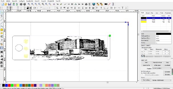
① Import an image from internet.

② Select your image and select vectorize the path. Play with the different technics and tolerance of it. Then I had great result.
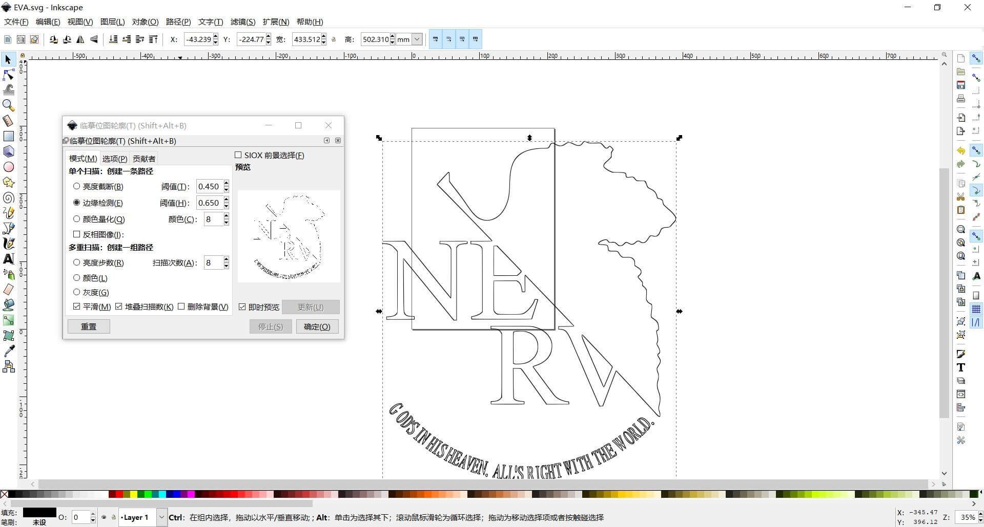
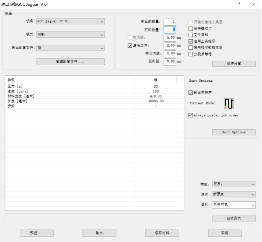
③ When I click on Cutting I can change the parameter of my machine. I start with Force:80g/f; Speed: 108cm/s.
④ Cut all my pieces I need.


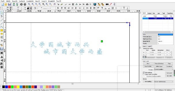
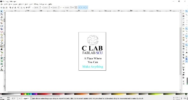
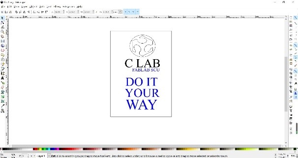
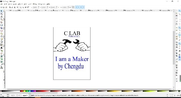
To test the vinyl cutting machine I decided to think in a logo to decorate my lab. Here is the own design I prepared and used:
Then I have to cut them, so I must adjust the parameters and start cutting. Note that the parameters that you can change are:
Speed: It is important to configure it looking at the material and the design. If it is a complicated design is better to set a low speed to not peel the paper by error.
Force: It depends on the material and hardness, if you set a too high force it will stick out the vinyl and mess up your design.
Passes: In most of the cases with one pass it will work fine, but sometimes it could help to ensure that the cut is done.
When it cut done, I pasted the picture on the KT board. So here are them look like.