Fab Academy 2020
17. Mechanical design and machine design
17. Mechanical design and machine design
Mechanical design and machine design
This week lesson was heavy for us with lots of information to absorb. Previously used to be a two-week lessons had been combined into one week.
The task for this week is to build a machine which consist of a mechanical portion and and an electronic portion.
The mechanical portion involves designing the
physical movable parts like the gear, pinion, rack, rail, or other parts. The electronic portion will automated the whole process to control all the movable parts and making them move.
On the next morning (after yesterday night lesson), our team met up online via MS Team app to discuss on the project. We have a few ideas on what we wanted to make, but one idea stood up the most.
Our team had decided to build an automatic (sensor-based) hand sanitizer dispenser machine.
In view of the ongoing Covid-19 outbreak across the world, the team felt that making a hand sanitizer dispenser machine would be a meaningful and useful project. The hand sanitizer dispenser machine would be placed in the SP Fab Lab, and
probably in other workshops within our school in the future.
The proposed machine is able to sense the presence of a user's hand and automatically dispense the hand sanitiser
solution onto the palm of the user, without the need for the user to touch the bottle. What's differentiate us from those DIY/Fab. hand sanitizer dispenser available online is that our machine would be able to hold a few bottles in the machine
and once the current bottle of the hand sanitizer solution is empty, the machine will automcatically switch
to the next bottle.
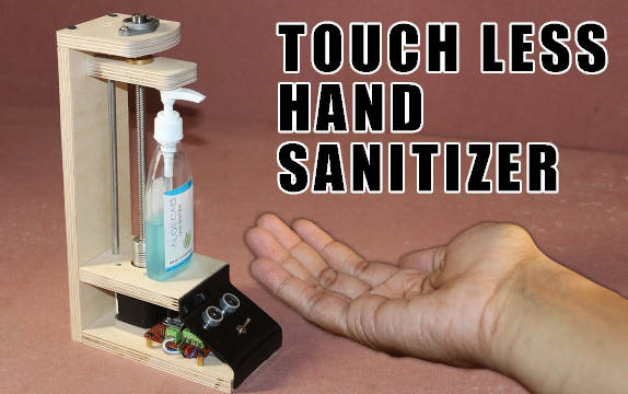
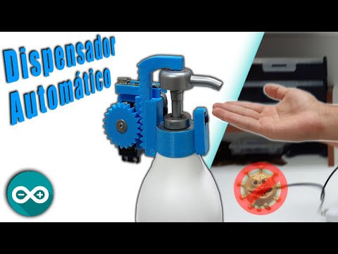
What been done before :
The team had found these videos on Youtube which provided us some ideas on how to start.
Our team members and assigned duty are as follow :
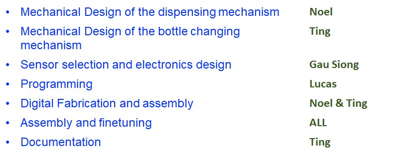
The team began to break out into two groups with one group consist of Ting Kok Eng and Noel working together on the mechanical portion while another group consist of Yeo Gau Siong and me are working on the electronics design. Each of us
in
turn also has our individual specific task to focus on. Like Gau Siong will handle the sourcing for the servo motor while I am sourcing and testing the stepper motor.
Later on when the SP Fab Lab was openned, we worked together on the other parts of the machine.
The SP Fab was still closed this week due to the circuit breaker. Our means of communication include meeting online via MS Team app., use of 'Whatapps' app on our mobile phone to communicate and share information with each other.
This web page documented my individual portion for the electronics in the project.
The team had discussed online and came up with two proposed designs, one being a long rectangular machine (where the hand sanitizer bottles will move in a linear manner), while the second design is a circular design (where the hand sanitizer
bottles will be rotated in a circular manner).
Yeo Gau Siong and I are in charge of electronics and we had came up with the following initial design for the proposed hand sanitizer dispenser machine.
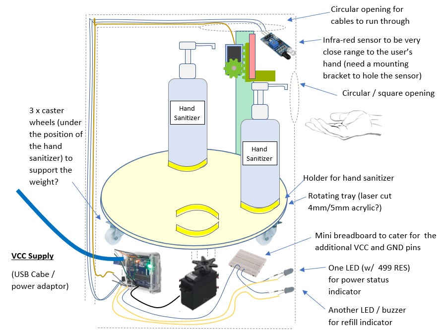
Initial electronic design drafted out on the 3rd day from Project start date (focusing only on the electronics)
Dispenser bottle :
The dimension of the hand sanitizer bottle was provided by our team member Ting :
height 183mm
Diameter 60mm
Total liquid volume is 300ml
Volume per squirt is 1ml
The depressed height is 171mm, a drop of 12mm
A counter is used to track the number of pumps carried out.
Explanation of initial electronic design :
1. 'Power status LED' lit up when machine is switched on
2. Infra red sensor will detect object at a fixed distance (eg. 7cm)
3. If sensor detects an object (the user hand), the servo motor in the 'dispensing mechanism' will be activated to pump out the liquid onto the palm of the user. This is done by moving the pinion gear down the rack, to perform a
compression.
4. A counter, eg. "pumpCount", is used to track the number of pumps made. "pumpCount" increase by "1"
5. When "pumpCount" reaches "295", or which the bottle is deem to be empty. The stepper motor in the 'bottle changing mechanism' will be activated to rotate the base by xxxx steps to position the next bottle just beneath the dispenser
mechanism and ready to be use
6. "pumpCount" reset to zero
7. Another counter "bottleCount" will increase by 1
8. When "bottleCount" is 3 (or at the last bottle) and "pumpCount" reaches "250" (or almost empty), the 'refill status LED' will light up or a buzzer will sound off to notify the Technical Executive to top up. After refilling, the system reset
all
counter to zero
Yeo Gau Siong and I had discussed and shortlisted the following electronics items suitable to be used and following is a brief description of the items. The next stage is to test out these components with its coding, observe the operation and and see if it is suitable to be used in the final product.
|
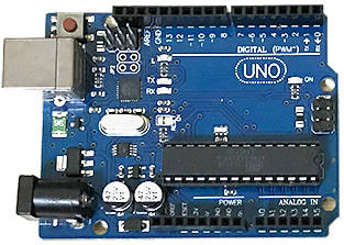
Microcontroller : Arduino Uno
Our team is using the Arduino Uno broad which is readily available in the Fab Lab and we are familiar with it. Another option is the Arduino Nano board, but we will have to purchase it online. Pulse width modulation in Arduino Uno The Arduino Uno does not have a DAC (digital-to-analog converter) which is capable of converting digital to true analog signal. What is does is using a technique called pulse width modulation or PWM. PWM is the primary mechanism for controlling most DC motors. PWM produces pulses (eg. 5V) at regular intervals (or also known as period). Pulses in a PWM have the same height and period, but the pulse width may vary over the course of the signal. The ratio of the pulse width to the period is the duty cycle. The duty cycle is the value that determine the time width of the pulse relative to the time between the pulse. The value is between 0 (always off) and 255 (always on). (Matthew Scarpino, 2016, Motors for Makers, p157) PWM allows the Arduino to create an average voltage value between 0v and 5V. The Arduino Uno pins that can be used with PWM are pin 3, 5, 6, 9, 10,11 and these pins are marked by the "~" symbol. |
|
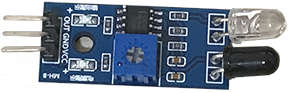
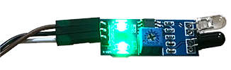
Infrared Obstacle Avoidance Sensor Module Both infrared sensor and Ultrasonic sensor are two possible sensors to be used, but we chose to use the infrared sensor instead. The infrared sensor module uses IR emitting LED and IR Receiver pair to detect obstacle in front of the sensor with a distance between 2 to around 40cm, and a detection angle of 35°. When the sensor detects an obstacle (the hand of the user), the signal LED indicator lights up, and produce an output digital signal (a low-level signal) in the OUT pin. The sensor has a potentiometer which can be adjusted to change the detection distance. |
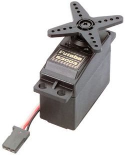 Photo from https://servodatabase.com/servo/futaba/s3003 |
Futaba S3003 Servo Motor Yeo Gau Siong and I planned to use servo motor in place of stepper motor as servo motor is easy to program and it is smaller in dimension, only require three wires, as compare to the stepper motor which will require a motor driver, a large number of wires and probably runs on a higher voltage. Motor sizing and torque When comes to motor, 'torque' is like force but acts in a circular arc and it rotate about a specific axis. Torque is the measure of how much force require to move (or rotate) the object (or load) or simply means what is the maximum load they can turn per revolution. It is important to select a motor with enough torque required to move the torque load and keeps it spinning in a desirable speed. The team selected the Futaba S3003 Servo Motors for our project which runs on 4.8V to 6V and have a higher torque. Specifications of Futaba S3003 Servo Motor Torque: 4.8V: 44.00 oz-in (3.17 kg.cm) 6.0V: 57.00 oz-in (4.10 kg.cm) Speed: 4.8V: 0.23 sec/60° 6.0V: 0.19 sec/60° Weight: 37.0 g Dimensions: Length: 39.9 mm Width: 20.1 mm Height: 36.1 mm |
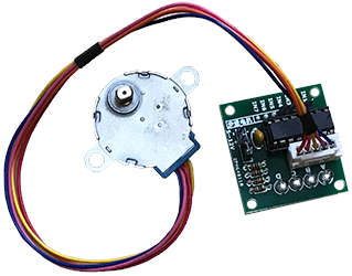
28BYJ-48 Datasheet from datasheetspdf.com ULN2003 Datasheet from electronicoscaldas.com |
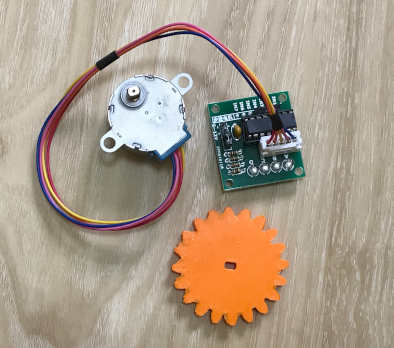
5V 28BYJ-48 stepper motor and ULN2003 motor driver The 28BYYJ-48 is a widely used unipolar (5-wire 4 phase) stepper motor running on 5 volts and connected to the ULN2003 motor driver. Stepper motor can moves more accurately and precisely than servo motor, and they can rotate 360 degree whiles a servo can only rotate up to 180 degree. Stepper motor is much easy to control. However stepper motor move in a lower speed than servo motor. The ULN2003 can produce a high current gain (eg. 5V ~ 9V) to drive the motor from the low current supply (5V) from the Arduino Uno. Specifications Motor Type: Unipolar Stepper Operating voltage: 5V Step angle: 5.625 x 1/64 (5.625°/64) Pull in Torque: 300 gf.cm In-traction Torque: >34.3mN.m(120Hz) Detent Torque: >34.3mN.m DC Resistance: 200Ω±7% (25) Insulation Resistance: >10MΩ (500V) |
 Datasheet from www.datasheet4u.com 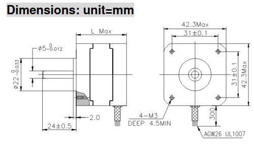 Image from Datasheet (www.datasheet4u.com) for illustration purpose |
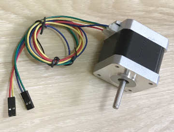
NEMA 17 stepper motor (model : 17HS4401) The NEMA 17 stepper motor (model : 17HS4401) is a bipolar hybrid stepper motor with a 1.8° step angle (200 steps/revolution). The tiny Arduino 28BYJ-48 Stepper Motor with a torque of around 0.82 kg-cm and steps at 64 steps per resolution is too weak to meet our needs, so I explore the possibility of using this stepper motor. Technical Specs : 'NEMA 17' is a very common type of stepper motor, the term NEMA 17 tells of it is of a standardize faceplate size. Example 17 means it is 1.7 inches (divided by 10). Bipolar tells of that the motor runs on a 4-wire setup, while as a unipolar motor runs on a 5-wire setup. Step angle is an important factor as it specifies how many degree each step turns, and a total of 200 steps will make a complete circle of 360 degree. Current tells of its operating current require for the desired load. Rated Current is the current limit of the motor to prevent any bad thing happening Holding torque tells you how strong the motor is. Detent torque is how much the stepper motor can hold a load in place when there is no current applied to the windings (for example, in a power-off condition). Specifications Motor Type: Bipolar Stepper 3.3 and 5 V compatible control logic Operating voltage: 8V to 35V Rated current : 1.7A Coil resistance : 1.5 ohm Step Angle: 1.8 deg. (200 step/revolution) Holding Torque: 40 N-cm (4.08 kg.cm) Detent Torque : 2.2 N-cm (0.22 kg.cm) Weight: 280g Dimensions: Frame Size: 42.0 x 40.0 mm Body Length: 40mm Shaft Diameter: “D” 21mm length 5mm diameter |
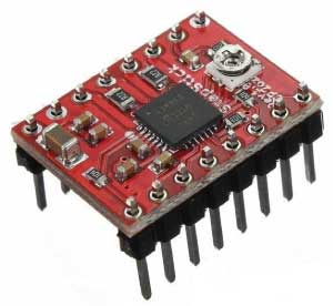 Image from https://howtomechatronics.com for illustration purpose Datasheet from www.pololu.com |
A4988 motor driver for stepper motor Controlling a Stepper Motor : The bipolar stepper motor has 4 wires and have 2 phases (A/A1, B/B1), therefore the wirings on the Stepper Motor are color coded: A-Black, A1-Green, B-Red, B1-Blue. Note: Some stepper motor might have different color coding for the wiring, but you can tell which wires are paired together by testing the resistance between them. In addition, if you connect A/A1 instead of B/B1, the motor will still turn. The bipolar stepper requires two H bridges for control. A4988 stepper motor driver : Here we are using the A4988 (dual H bridges) microstepping driver module to control the stepper motor. This way it will free up lots of processing load from the Arduino board. The A4988 is a microstepping driver for controlling any bipolar stepper motors which has 4 wires. The A4988 has built-in translator for easy operation. This means that we can control the stepper motor with just 2 pins from our controller; one for controlling the rotation direction and the other for controlling the steps. However, using the two wires setup on the A1988, the driver will operate in full-step mode. ~ Source : https://howtomechatronics.com Wiring for the A4988 with the Arduino Uno and the NEMA 17 Stepper Motor 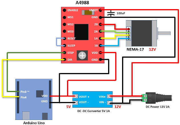
The Direction pin controls the rotation direction of the motor and we need to connect it to one of the digital pins on our microcontroller (Pin 4). The Step pin controls the mirosteps of the motor and with each pulse sent to this pin the motor moves one step. Next is the Sleep Pin is active logic low and will puts the board in sleep mode for minimizing power consumption when the motor is not in use. Next, the Reset pin is active logic low and sets the translator to a predefined Home state. The A4988 module can be powered by DC supply up to 35 V and can handle up to 2A. It is recommended to place a capacitor very near to power supply pins for decoupling; to smooth out any current surges (especially when voltage supply for the motor is very high). ~ Source : https://howtomechatronics.com Current limiting The A4988 controls one bipolar stepper motor of up to 2A output per coil and operates from 8V - 35V. One way to maximize stepper motor performance is to use as high of a voltage as is practical for your application. In particular, increasing the voltage generally allows for higher step rates and stepping torque since the current can change more quickly in the coils after each step. However, the coil current should not to exceed the motor’s rated current to avoid damage to the motor. The A4988 driver IC has a maximum current rating of 2 A per coil, but the actual current you can deliver depends on how well you can keep the IC cool, so a heat sink is required. ~ Source : Pololu.com on A4988 Stepper Motor Driver The A4988 supports such active current limiting and has a trimmer potentiometer on the board used to set the current limit. I used a multimeter and placed the red lead on the potentiometer and black on the logic GND pin beside it to measure the reference voltage. Use a very small screwdriver to turn the screw of the potentiometer to adjust the voltage. If you have difficulty with the screwdriver, you can try using a small long nose pillar but be careful not to pull up the screw. When using the driver in full step mode, the current is limited to 70% of the maximum current limit, so accordingly you have to set the current limit almost 40% higher. Example if you want the current through each coil to be 1 A in full-step mode, you would need to set the current limit to be 40% higher, or 1.4 A. ~ How To Mechatronics : How To Control a Stepper Motor with A4988 Driver and Arduino ~ Source : Pololu.com on A4988 Stepper Motor Driver To calculate amps from measured VREF: A = VREF / 0.8 Example if your stepper motor maximum current is 1A , then to calculate VREF required for a target current is VREF = A * 0.8 VREF = 1 * 0.8 = 800mV But if you are using full step mode, then VREF = 1.4 * 0.8 = 1.12 V So I set the voltage to around 1.12V, so the current limiting equal around 1A. |
|
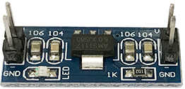
DC to DC step down power module This small and light-weight power regulator expansion module will step down a 6V to 12V voltage supply to 5V (+-0.05v error ) 800mA. |
|
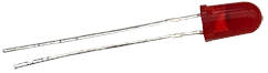
LED Two 4/5mm LEDs are used in the machine as status indicator lights and each LED to be connected to a 470 ohmn resistor. The long lead (anode) attaches to signal pin while the short lead (cathode) to GND. |
|
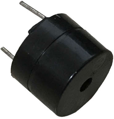
Mini piezo buzzer A mini piezo buzzer is used to generate a sound that will alert the Staff to refilled the empty bottles. The long lead (anode) attaches to signal pin while the short lead (cathode) to GND. |
|
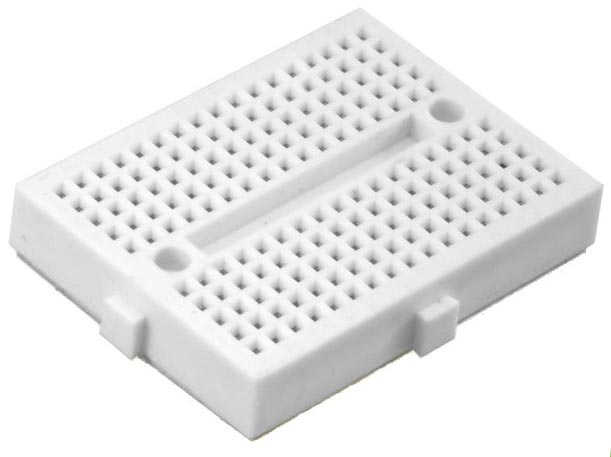
Mini breadboard A mini breadboard (white) of 170 tie-points for more VCC and GND slots. |
I am new to motors, as I have not used any motor in my previous weeks, so it took me quite a while to learn, especially the NEMA17 Stepper Motor with the A4988 driver which require a different setup, like a seperate higher voltage supply.
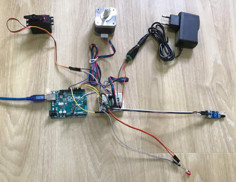
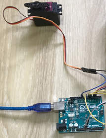
Wiring to test out the servo motor as well as the stepper motor :
I wired up the standard servo motor as well as the standard stepper motor from the Arduino kit to do my initial testing and programming, before moving to bigger or more complex motors.
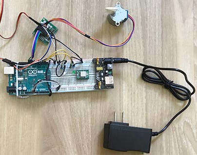
Testing on basic Arduino servo and stepper motors :
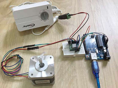
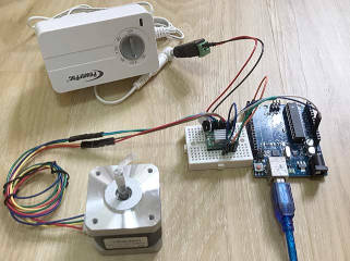
Testing on Nema 17 stepper motor :
The NEMA17 motor require a seperate power supply (like 12V, 2A). The A4988 can support up to 2A.
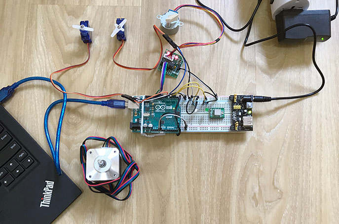
Putting all the pieces together and test :
Moving on to assembly all the pieces together and testing it out. Using a mini breadboard this time. Later on I added in the buzzer, but the volume is too soft, and so I did not put in the buzzer.
I had written down the coding for the various pieces of the hardware for useful refereence as well as explanation of our final coding. My team member GS will integrate his coding with mine later on.
|
Infrared sensor coding (draft):
// for infra-red proximity sensor module |
|
Servo motor coding (draft):
// Include the Servo motor library |
|
28BYJ-48 stepper motor coding (draft):
// Include the Arduino standard library:
// Include the AccelStepper library: |
|
NEMA 17stepper motor coding (draft):
// Include the AccelStepper library: |
On selection for stepper motor :
I decided not to use the NEMA17 stepper motor as it is quite big (1.7 x 1.7 inches), heavy and bulky, but instead used the 28BYJ-48 stepper motor. The NEMA17 is also too troublesoome to
setup and pose a danger as we would need to use a high voltage and current VCC supply near a liquid dispensing machine...
The following 'Part List' is the final selection and the actual components used in the making of our hand sanitizer dispenser machine.
Parts List :
| No. | Part No. | Part Description | Qty | Remarks | Microcontroller |
|---|---|---|---|---|
| 1. | Arduino Uno board R3 | 1 | Breadboard | |
| 2. | Mini breadboard 170 tie-points to cater for the additional VCC and GRN pins | 1 | Sensor | |
| 3. | Infrared obstacle avoidance sensor module for Arduino | 1 | DC Motors | |
| 4. | SM-S4315M | Spring RC SM-S4315M 2BB metal gear high torque servo motor |
1 | Info |
| 5. | 28BYJ-48 | 28BYJ-48 stepper motor, unipolar | 1 | Info |
| 6. | ULN2003 | ULN2003 motor driver for 28BYJ-48 stepper motor Supply Volts: 5-12VDC, Maximum Current per output : 500mA |
1 | Info | LED Status indicator |
| 7. | LEDs | 2 | ||
| 8. | 470 Ohm Resistor | 2 | Power | |
| 9. | AC to DC Power Adaptor UK plug (5.5mm connector) | 1 | Wiring | |
| 10. | Jumper wires (or a roll of dupont electrical wire to manually cut and connect with Male/Female pin terminal and dupont jumper housing) |
20 |
Tools :
The following Tools were used for testing purposes, etc.
| Tools | ||
|---|---|---|
| a. | Digital Multimeter for testing purposes | 1 |
| b. | Small screwdriver | 1 |
| c. | Test pen (Optional) | 1 |
| d. | Wire crimping tool (Optional, to crimp dupont wire and header connectors) | 1 |
| e. | Soldering tool and soldering material | 1 |
| f. | Securing means : Glue gun, electrical PVC insulating tapes, small cable ties, others if needed | 1 |
Finally the team met up in the SP Fab Lab and began to put everything together. Before assembly all together, both Gau Siong and I tested each individual electronic components (i.e the infra red sensor, servo and stepper motor) to make sure
that these individual components are working properly first. Testing was done with the Arduino board and just the electronic compenents and just running the minimum coding .i.e to see that the motor can turns.
Gau Siong and I putting in and integrating all the electronics. We also tested out the coding on my notebook testing the respective componenets.
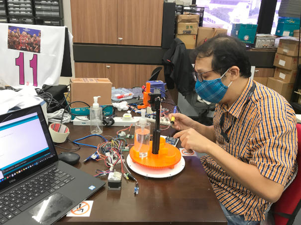
Ting adjusted and 3D printed the gear again to fit nicely onto the stepper motor.
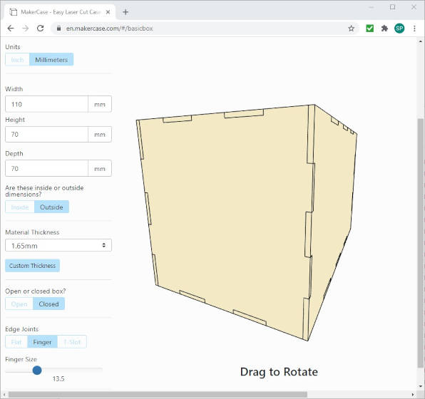
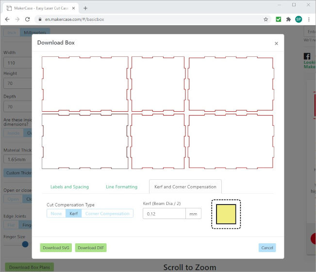
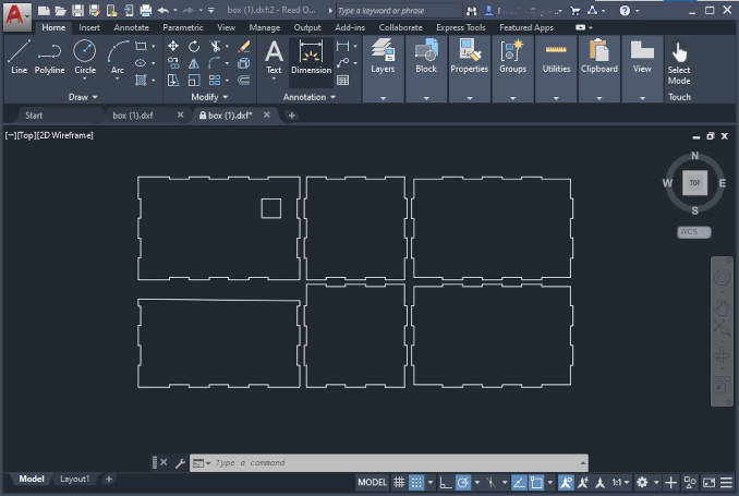
I fabricated the enclosure to cover up the electronics.
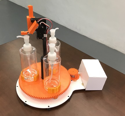
Our finished product. Gau Siong and I recorded the video demostration which is found on our group page.
The final coding for our machine and it is self explanatory.
/*
  Hand_sanitizer_dispenser.ino

  Note :
  For video recording and demostration purpose,
  the max. number of pump was set to 3, therefore
  after three pumps, the stepper motor will be activated
  to rotate the base and change to the next bottle.

  Components used :
  1. Arduino Uno R3 board
  2. Infrared Proximity Sensor
  3. Servo motor
  4. 28BYJ-48 Stepper motor and ULN2003 motor driver
  5. 2 LEDs

  The work is provided for academic purpose for Fab Academy 2020.
  Users accept all as is, no warranty is provided, no call/email
  from users will get a response. Users accept all liability.
*/

#include <Servo.h>
#include <AccelStepper.h>

#define END_STATE 3  //max compression

// for 28BYJ-48 stepper motor with ULN2003 driver
#define motorPin1  8      // IN1 on the ULN2003 driver
#define motorPin2  9      // IN2 on the ULN2003 driver
#define motorPin3  10     // IN3 on the ULN2003 driver
#define motorPin4  11     // IN4 on the ULN2003 driver

int sensor_pin = 2;//IR sensor at pin 2
int tap_servo_pin = 3;//tap servo at pin 3

int val = 0;//variable for IR sensor
int count = 0;//variable for counting compression

Servo tap_servo;

// Create stepper motor object
// MotorInterface 4 for 4-wire in full step mode
AccelStepper baseMotor(4, motorPin1, motorPin3, motorPin2, motorPin4);


void setup()
{
  pinMode(5, OUTPUT);
  pinMode(6, OUTPUT);
  digitalWrite(5,LOW);
  digitalWrite(6,LOW);

  pinMode(sensor_pin, INPUT);

  tap_servo.attach(tap_servo_pin);
  tap_servo.write(0);

  // for 28BYJ-48 stepper motor with ULN2003 driver
  baseMotor.setMaxSpeed(1000);     // The desired maximum speed in steps per second
  baseMotor.setSpeed(150);         // The desired constant speed in steps per second, use with runSpeed()
  baseMotor.setAcceleration(90);   // The desired acceleration in steps per second per second
  baseMotor.setCurrentPosition(0); // Set the current position to 0:
}

void loop() //main code run repeatedly
{
  val = digitalRead(sensor_pin); //read IR sensor
  if  (val==0) //IR sensor detected object
  {
      delay(800);// wait for sensor to stabilize
      if (val==0)//check again for object detected
      {
        digitalWrite(5,HIGH); //red led turn on to indicate object is detected
        digitalWrite(6,LOW);  //green led turn off to indicate tap servo is not ready to turn
        tap_servo.write(80);  //tap servo is turning to 60 degree i.e. executing compression
        delay(800);
        tap_servo.write(0);   //tap servo is turning to 0 degree i.e. release compression
        delay(800);
        count++;              //counting compression executed by tap servo
      }
   }
  while(val==0) //no executing compression if object remain detected
     {
      tap_servo.write(0); //tap servo remain at 0 degree
      delay(200);
      val = digitalRead(sensor_pin); //read IR sensor
     }
      digitalWrite(5,LOW); //reset red led
      digitalWrite(6,HIGH); //reset green led
  //check counter for max compression on a bottle used, when max is reached than change bottle
  if (count==END_STATE)
  {
    delay(500);

    baseMotor.moveTo(3446);       // Set the target position:
    baseMotor.runToPosition();    // Run to target position with set speed and acceleration/deceleration


    for(int x = 0;x<=5;x++) //blink LEDs x times during servo turning to 180 degree
    {
    digitalWrite(5,HIGH);
    digitalWrite(6,LOW);
    delay(100);
    digitalWrite(5,LOW);
    digitalWrite(6,HIGH);
    delay(100);
    }

    baseMotor.setCurrentPosition(0); // Set the current position to 0:

    for(int x = 0;x<=5;x++) //blink LEDs x times during servo turn to 0 degree
    {
    digitalWrite(5,HIGH);
    digitalWrite(6,LOW);
    delay(100);
    digitalWrite(5,LOW);
    digitalWrite(6,HIGH);
    delay(100);
    }
    count=0; //reset counter after bottle changed
  }
}
Note : For video demostration purpose, the max. number of pump was set to 3, therefore after three pumps, the stepper motor will be activated to rotate the base and change to the next bottle.
Duration : 51 secs
No Audio
There was a bit of delay as laast minute I had to attend to an urgent work matters, so I was rushing and there was a bit of delay on my part.
I am new to motor and now learn a lot about motor. After we took the video showcasing that our machine worked, I felt a great sense of achievement for we had finally completed our machine building project. Everyone of us was happy with it.
There are many areas for improvements include :
- buiding a strong supporting column in the center, as every time the servo turns and pump the liquid, the supporting column tend to lean backward a bit. We should have tested this earlier on.
- Since we are using the Arduino Uno board, it be great to include a wifi module and to send notification to the Technical Executive to refill the bottles
- better cable management for the wiring
- using better motors
- Coding : Hand_sanitizer_dispenser.ino
- Enclosure for electronics in dxf file for laser cutting
- Matthew Scarpino, 2016, Motors for Makers: A guide to Steppers, Servos, and other electrical machines, Pearson Education, USA.
- Jody Culkin and Eric Hagan, 2017, Make: Learn electronis with Arduino, Maker Media, San Francisco, CA, USA.
- DIY Arduino based Touch Free Hand sanitizer dispenser on Youtube
- Dispensador Automático de gel y jabón antibacterial-Automatic hand sanitizer-Arduino-FABRIcreator on Youtube
- Source : Pololu.com on A4988 Stepper Motor Driver
- How To Mechatronics : How To Control a Stepper Motor with A4988 Driver and Arduino
- iknowvations : A4988 Stepper Motor Driver With Arduino Tutoria
- Makerguide.com: How to control a stepper motor with A4988 driver and Arduino