Here is our group works : week7
● Demonstrate and describe parametric 2D modelling processes
● Identify and explain processes involved in using the laser cutter.
● Develop, evaluate and construct the parametric construction kit
● Identify and explain processes involved in using the vinyl cutter.
● linked to the group assignment page
● Explained how you parametrically designed your files
● Documented how you made your press-fit kit
● Documented how you made your vinyl cutting
● Included your original design files
● Included your hero shots
Fusion 360
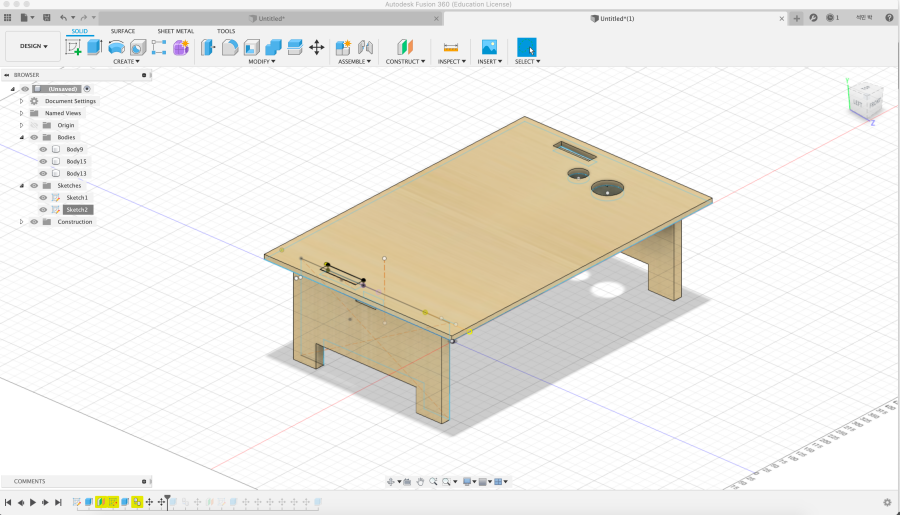
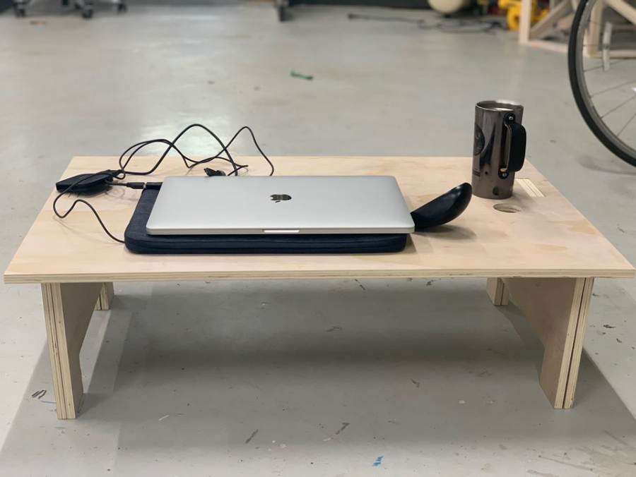
This week, I tried to make a desk on the bed using CNC.
I wanted to make a desk where I could put my laptop on the bed and put my beer on it.
When I sat down before designing first, I checked and designed the right height from my butt using a tape measure. The appropriate height was 230 mm.
● Material : ply wood 12T
● CAD : Fusion 360
And I didn't take the test with the cardboard, but I worked with the cc right away. Because there were only 3 kinds of designs.
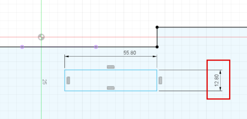
First, the Kerf value was given 0.4mm on both sides because it was designed to join the leg part and the top using a dogbone.
Just because you use 12T, you don't have to design the joint as it is. After testing the joints in group work, it was better to give 0.4 mm each.
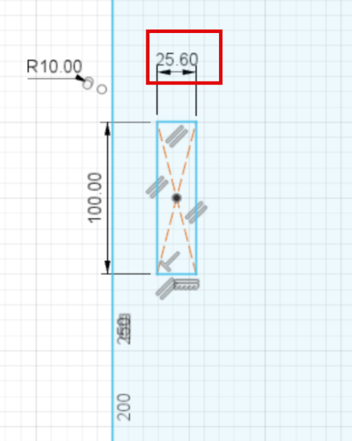
It added a joint in the middle because it would be less durable if only the top and the legs were connected. Similarly, the same kerf value was given.
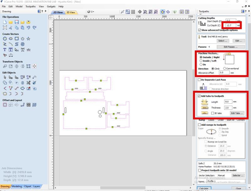
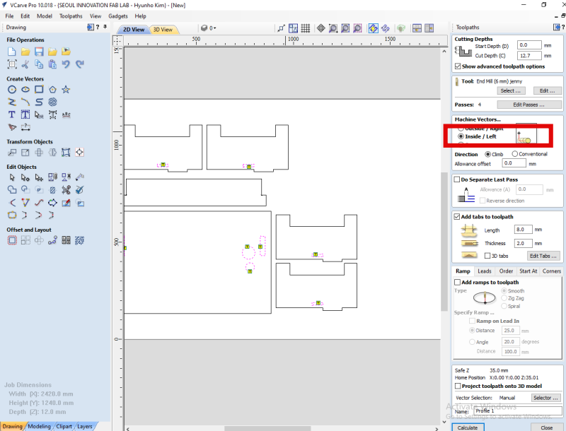
I used Vcarve software to use Shop Bot.
The toolpath that I used was outside the cutting, but I set it in two ways because the endmill had to pass inside and outside of the work.
And although the thickness of the material is 12T, it is not the same for each part due to the nature of the tree, so I worked about 12.7mm deep.
And after the milling, I put in a taps so that the work wouldn't twist.
The reason why tolerances and clearances should be considered important is that if this is not considered when working in the Shopbot, the machining should be done after the work. Because the condition of all materials is not always the same.
n addition, when cutting an object, you can set a difference in the entry method among several basic tool paths.
Also, the method of going back to where you cut and doing it again can delay the time, but it is also possible to go back and cut where you moved.
In some cases, as the end mill rotates, it may have to go slowly according to the material, it may have to go in as it rotates, and it may need to go in diagonally.
Such situations depend on design and materials, so you should refer to them.
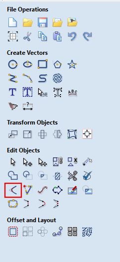
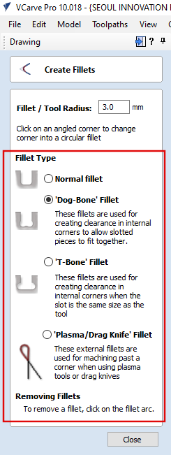
This is inside tool path. In fact, the end mill is circular and there is no right angle to the shape or part that goes inwards.
Therefore, you can use the dogbone design or other assembly features to create a design that can enter at right angles.
You can pre-design on Fusion 360 or add designs on Vcarve.
In addition, Nest function, which automatically changes alignment, is located in the lower right corner, which means that the line itself can be broken if the bagter files are not grouped. And you have to check it because it is not always arranged perfectly to save the material.
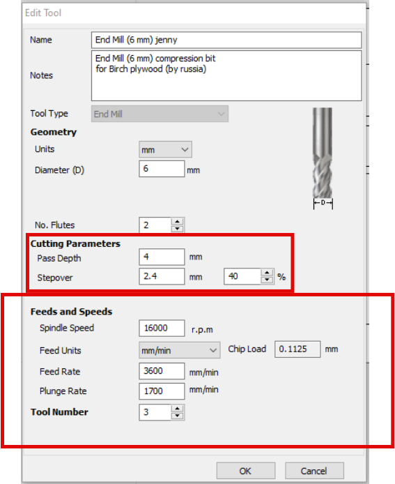
It's the end mill setting window. I used 2F 6mm Downcut Endmill and used good condition values among the result values of our group work.
●Pass Depth : 4mm
● Stepover : 40%
● Spindle RPM : 16000r.p.m
● Feed rate : 3600mm/min
● Plunge rate : 1700mm/min
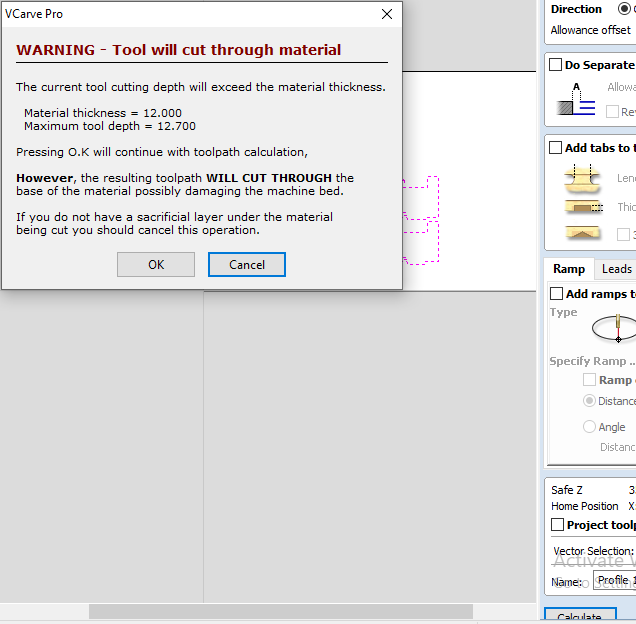
This warning is a message warning that the depth of the cut is different from the thickness of the material. I did it on purpose, but I always need to check the message.
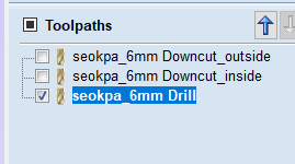
Work is carried out using three toolpaths.
The order is Drilling-> Inner -> Outer. The reason for putting the inside before the outside is to prevent the work from shaking.
There are two ways to get zero on the Z axis with a Shopbot.
This is the case of setting the zero after manually adjusting the material or the bad through the electric signal.
I got a zero on the material.
For settings through electrical signals, refer to Groupwork.
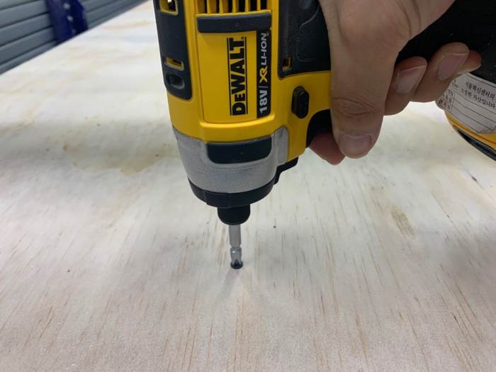
he reason for using a screw is to keep the bat and material in close contact.
Make sure that the screw is at right angles and rotate it without strain.
You may not miss it later!
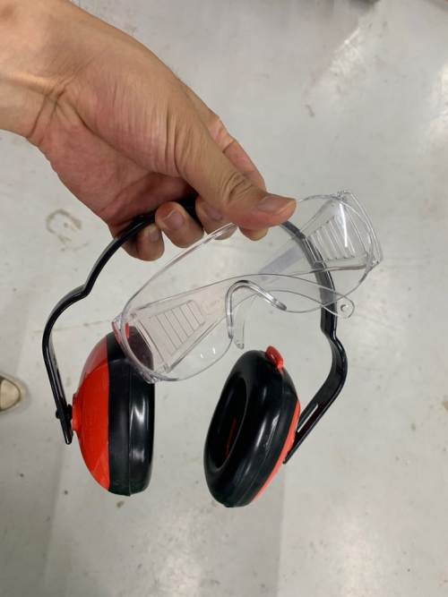
Prepare safety supplies before CNC starts!
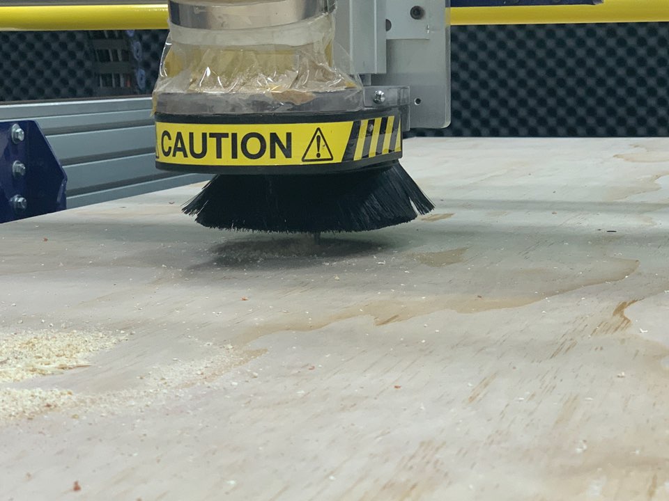
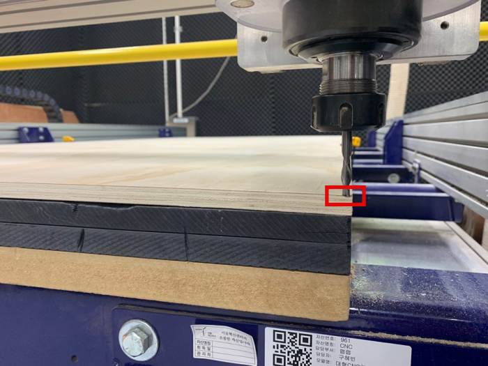
When milling is started, make sure that the end mill is well set at first start. Occasionally, accidents can occur further than zero. After that, when the milling starts, you can check it out by listening to the sound.
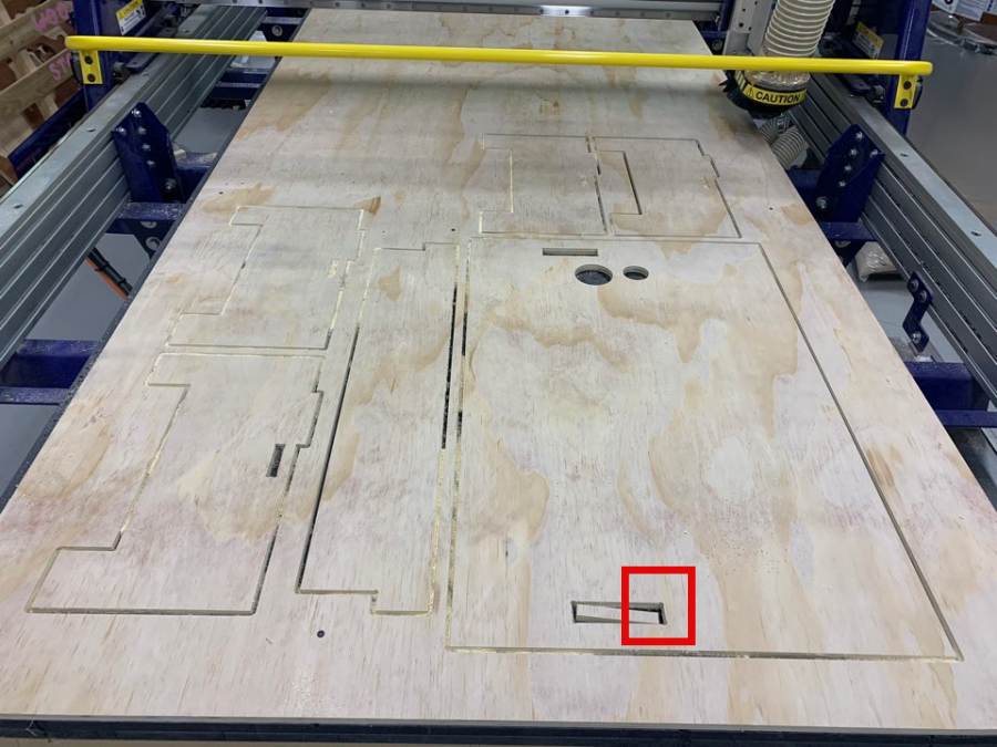
This is the scene after finishing 3 tool path. The size and number of Tab was insufficient during inside tool path.
As an option on the tabs, the length was 8mm thick and 2mm thick, but the thickness should be set to 4mm next to avoid leaving.
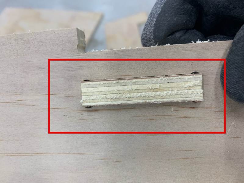
I checked Clearance while assembling. Experience in group work shows that the appropriate value has been set.
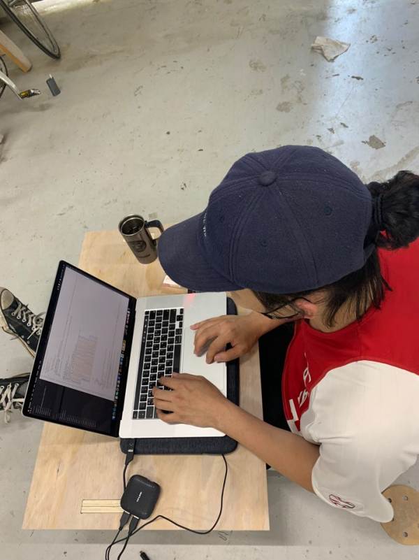
I sat down and checked the height and size.
It seems a little big on the side, but it seems to be the right height to use on the bed!
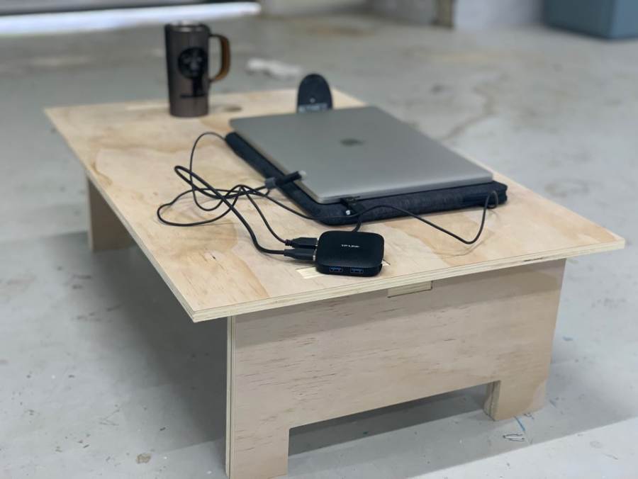
I checked to see if the tumbler was suitable for fixing the cup.
I used two trees in the leg part because it is easy to shake and cannot be fixed with just one leg.
DXF : Download
Fusion 360 : Download