3D Printing
Here is our group works : week5
This week, I tried the new DP200 3D printer. And the software used 3DWOX. First, I tested various printers with group work, and the link is on top.
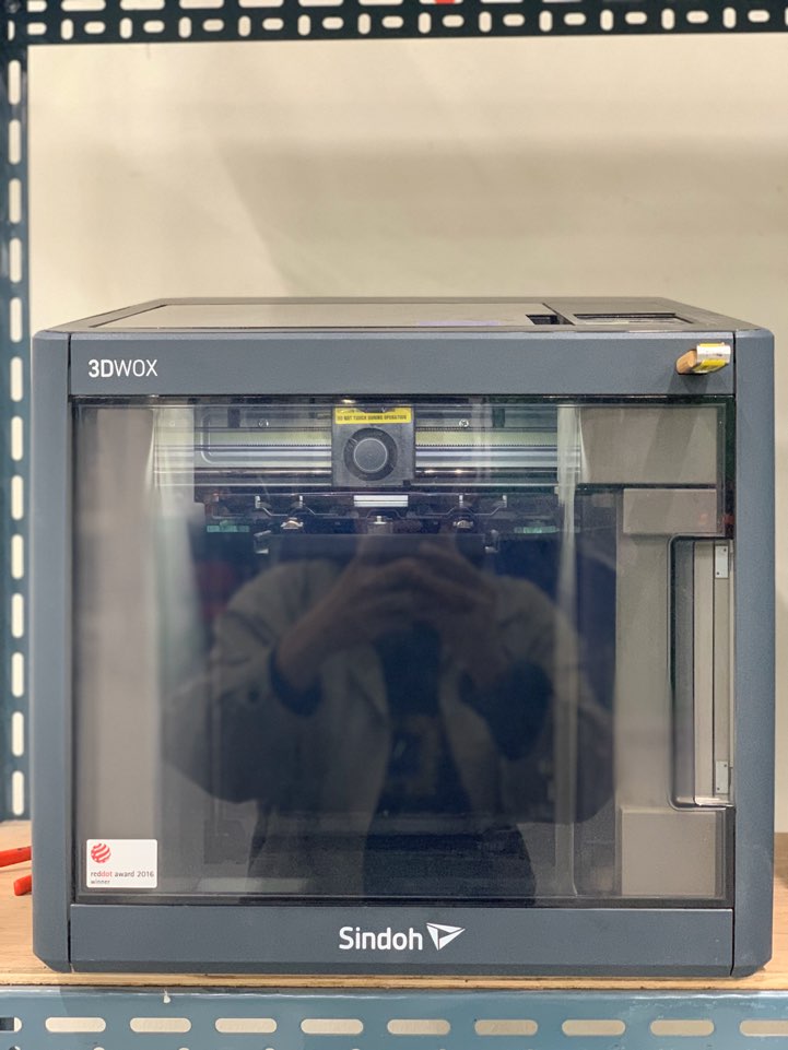
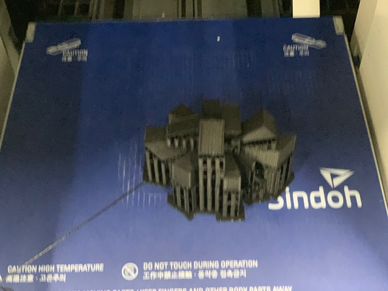
This is the DP200 printer. It is not an open type,it is enclosed to prevent so that it can prevent temperature and humidity well.
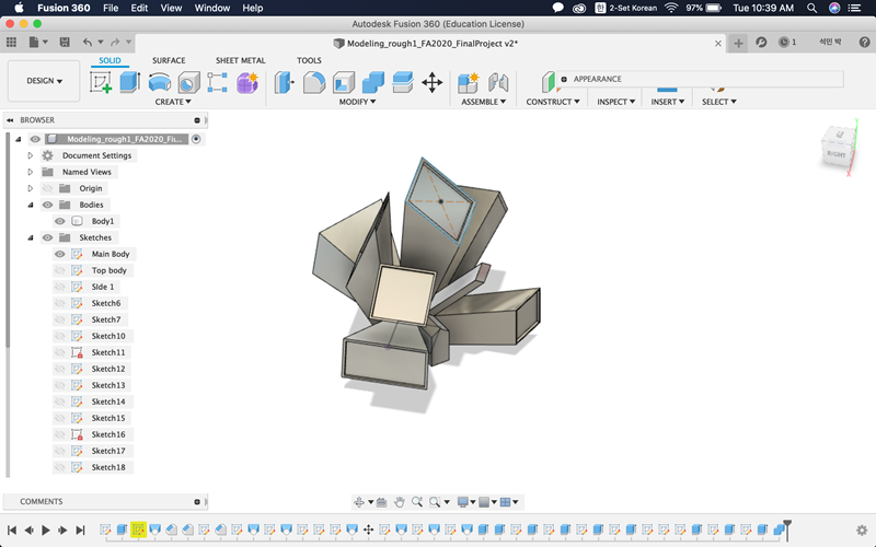
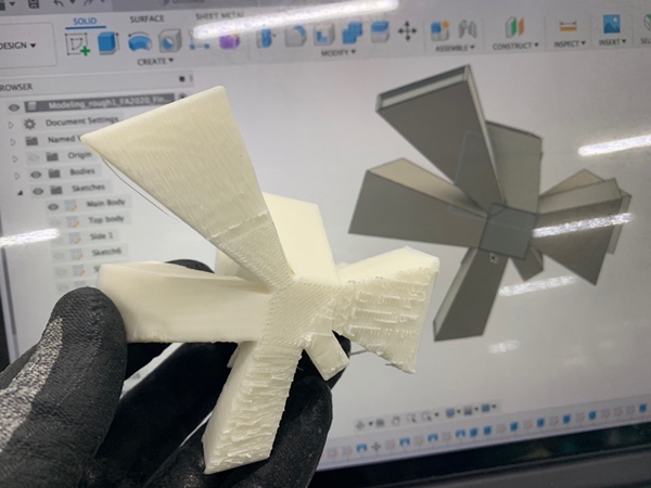
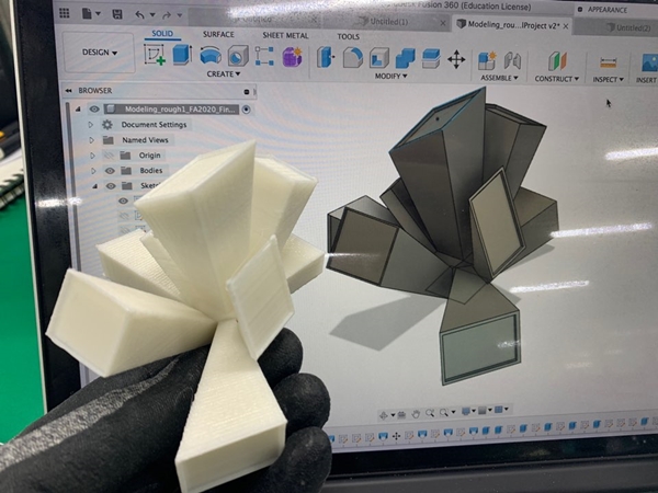
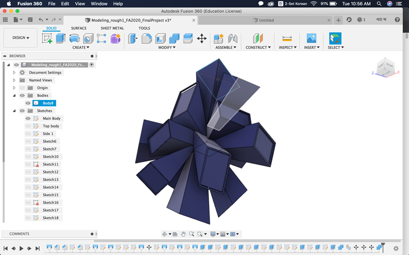
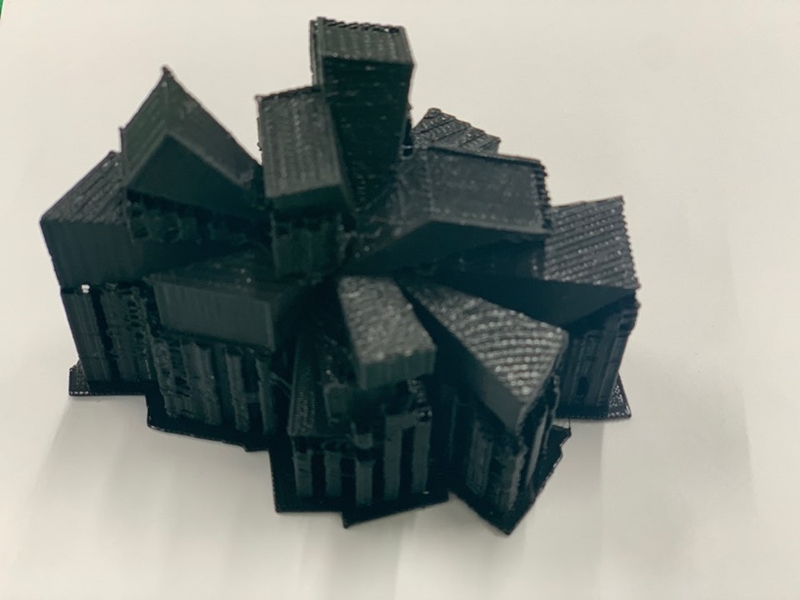
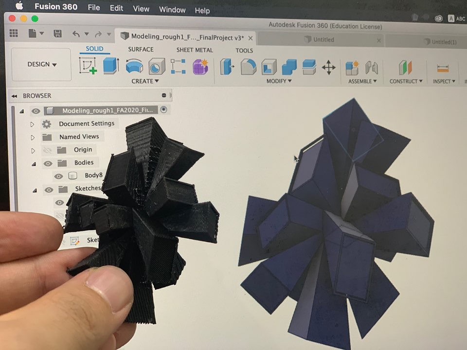
This week, I designed the final project sketch in about 1:20. Because the size of the top and bottom sides are different, the model was shaped using loft commands, and each of these lofted objects was made by rotating them. The shape itself is sharp and there are many gaps, so I wonder how the printing will turn out.
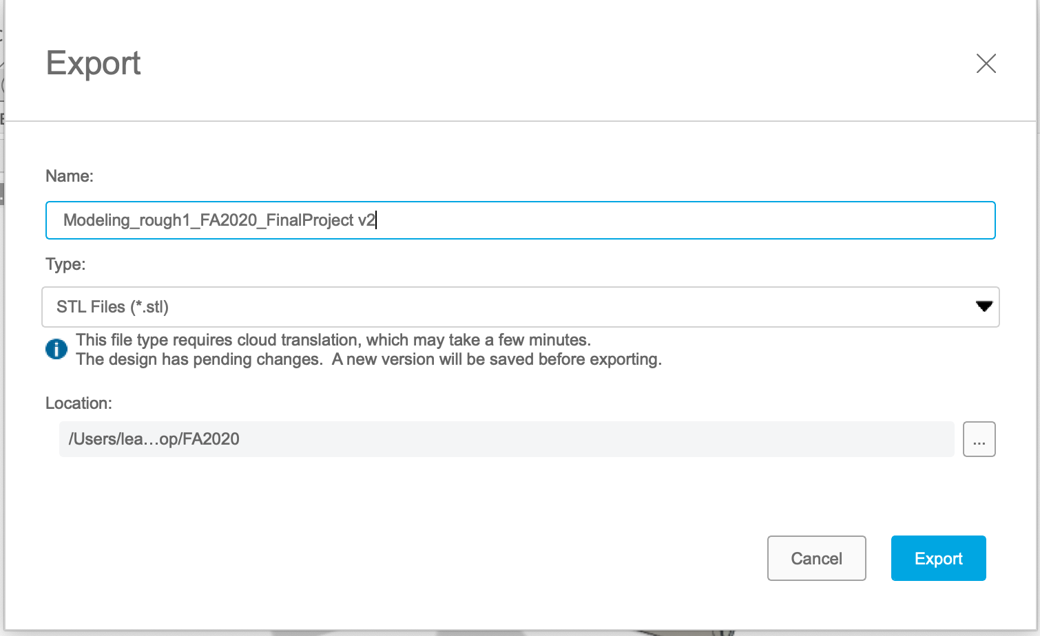
Export modeling on Fusion 360 and save it as STL.
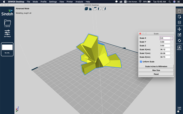
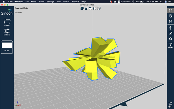
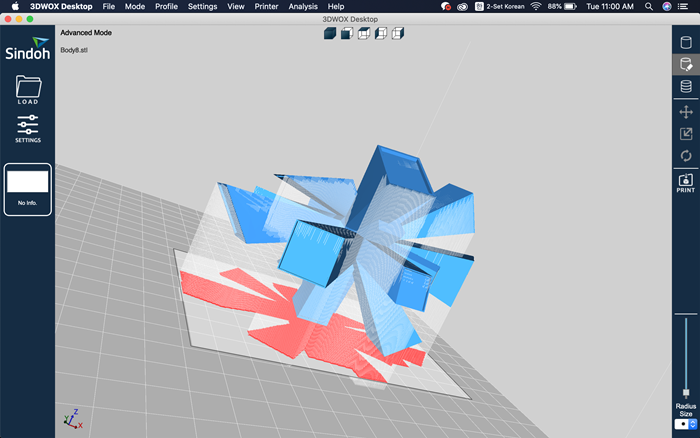
This is the first scene of 3DWOX. I called STL file through Load. And the size of the modeling was so big that we halved the size using scale change on the right.
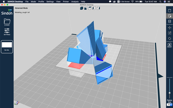
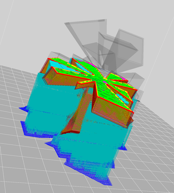
This is the scene where the supporter is added to the modelling. My modeling often required a lot of support because it was reverse-badged.
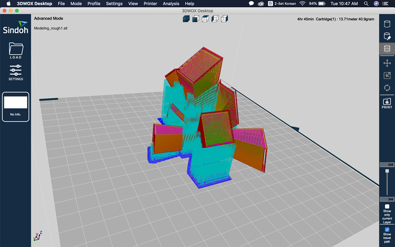
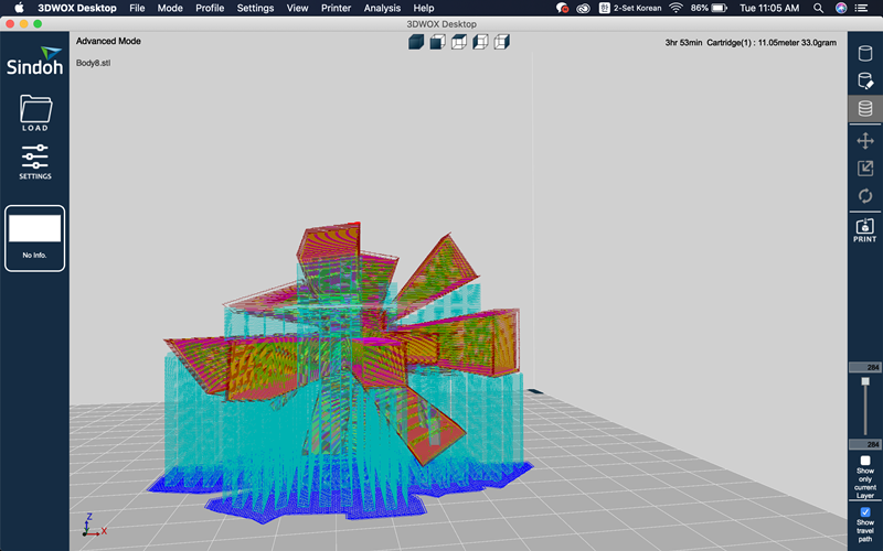
It's a screen that creates a supporter and looks at the G-code layer. It also shows the time and capacity it takes.
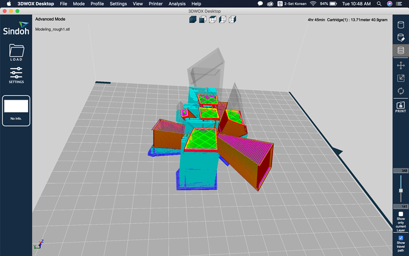
We can also see how the layer works.
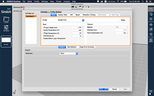
This is the 3DWOX output setting window. You can set layer height, nozzle temperature, bad temperature, infill, etc.
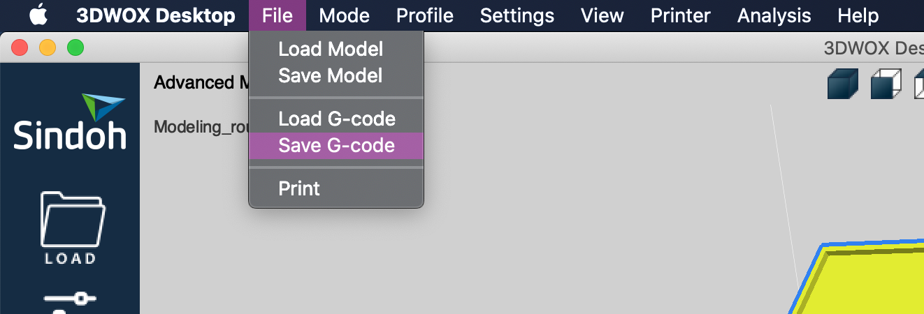
And set up with information obtained through group work and save as G-code!
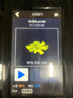
And after putting the G-code into the USB and recognizing it in the printer, selecting a file with the modeling name gives the above preview, including the percentage of additive time, temperature control, and completion!
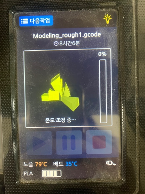
It's the printer that's making Raft. I think it's kind of a supporter that helps the production sit well on the bed.
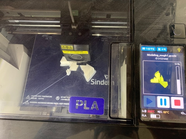
50 percent course!
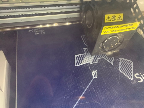
About 70% of the process!
And 100 percent! The bed can be hot, so be careful.
When removing the result, do not apply too much force and apply moderate force.
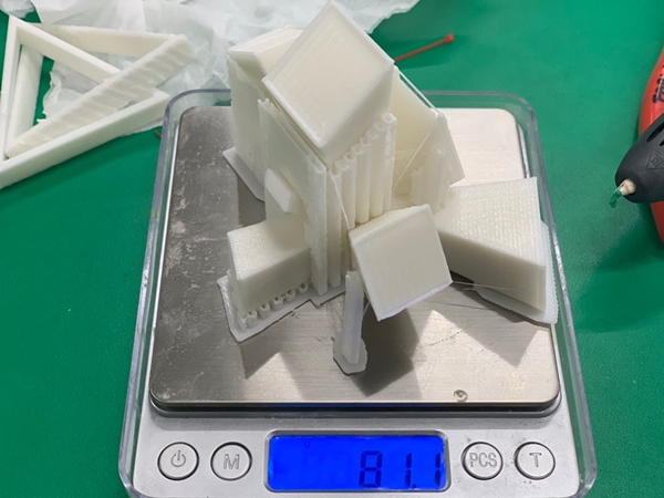
We weighed the supporters and the work together. It came out similar to the value shown in 3DWOX.
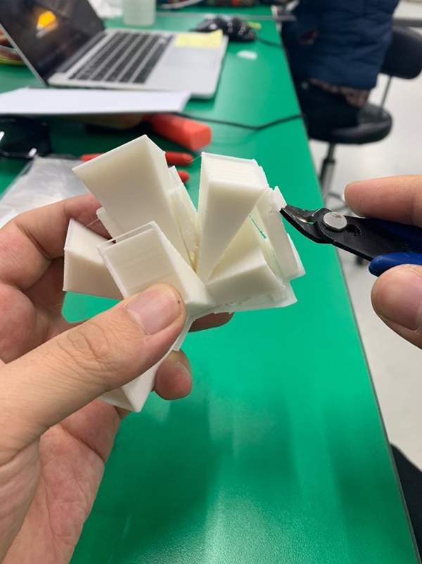
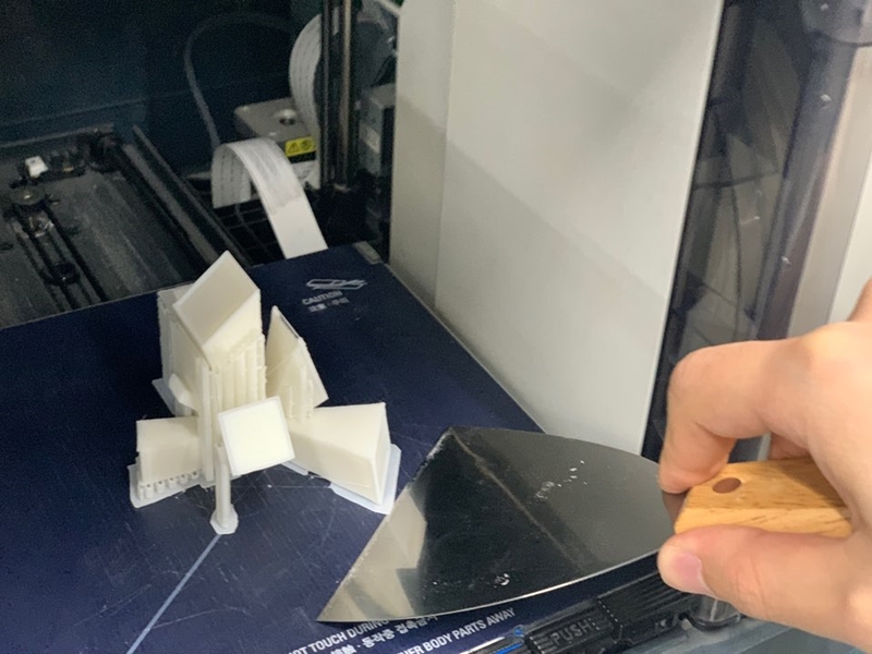
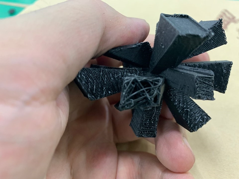
Use a nipper to remove the support. Be careful not to hurt your hand.
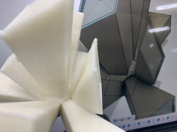
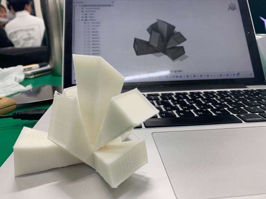
After removing the support, we compared it to the modeling to see how neat it came out.
It looks like the bottom. Removing the support leaves some residue on the surface. Post-processing seems essential.
I also checked other parts.
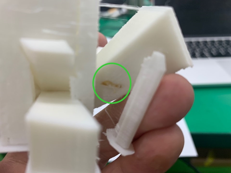
There was a little bit of burnt material here. It is not known whether the nozzle is a temperature problem or a filament problem. Do you happen to know?
I made a 3D printer to reduce the scale. Using surface surface, it seems that post-processing is necessary and useful equipment to preview the modeling of work.
Material - PLA
Bed fix form - raft
Layer height - 0.2mm
Wall thickness - 0.8mm
Top/bottom thickness - 0.8
Infill density - 30%
Nozzle temperature - 200℃
Bed temperature - 60℃
Filament diameter - 1.75mm
This time, Craig of Innovation FABLAB will be advised to print more complex structure modeling.
Similarly, 3DWOX was used to prepare the output.
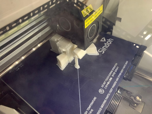
This time it's almost in the air.You have to print them out, so you can see how much the supporters need.
Check each layer through G-code formation.
Save and print G-CODE, hoping to fully implement so many supporters in need!
This time, it was made by reducing the amount of Infill to 10, because it took too long, so it started with a shortened version of 5.
This is what it looks like before it's finished and taken off the bat. It looks like some labor is needed..
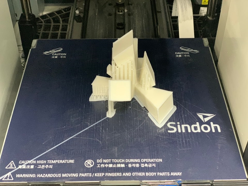
The appearance before the supporter is stable. I was curious about the inside, so I quickly removed the supporter.
There seemed to be a part here that failed to make a supporter. So the surface was distorted....
First of all, there are so many supporters, so I think it's inevitable that there's a lot of residue on the surface. While the shape itself is invariably good with modelling, the layer of the backbad part needs to be fully verified before G-CODE is created.
Material - PLA
Bed fix form - raft
Layer height - 0.2mm
Wall thickness - 0.8mm
Top/bottom thickness - 0.8
Infill density - 10%
Nozzle temperature - 200℃
Bed temperature - 60℃
Filament diameter - 1.75mm
Qustion and Explain
Q.Choose to use a raft for your object. What other adhesion options could you have selected?
Raft is an option to create layers so that objects can settle on the bed. So it takes longer to produce the result, but it can be stable because it does not attach itself to the bed. In addition to Raft, there is also a way to settle on a bed using Brim.
Q.Choose to use a 30% infill setting. Would you use the same setting if you printed this object again? Why / why not?
The reason why I gave 30% of the infill value was because I was curious about how strong the model was. There is no reason to choose this model again at 30 percent. 15 percent is strong enough and saves time.
Q.Printed a second object. What was its purpose, was it successful?
The second printing is to control the amount of support needed to print more complex structures, and to try how neat it looks when the design is complex. It wasn't successful. I think I didn't make good use of the information I got through group work. I think I missed one spot to give you a supporter.
Q.What did the group tests tell you about the amount of support your design would require. Which test most closely relates to your design? Would you use the same support settings if you printed this object again? Why / why not?
In Groupwork, we could see several values that could tell the moment the filament was broken when the 3D printer layered. Strength test,Surface test,Thickness test,Bridge test,Overhang distance test,Tolerance test etc The tests that could be referenced in my design were the support test and the Overhang Distance test Overhang, angle test.With that in mind, the next printing could reduce the number of supports, which would give us a little more time.
Modeling_v1 : Download
Modeling_v2 : Download
Here is final project for 3D printer : Link
3D Scanning
I tried 3D scanner. Actually, I haven't used it completely yet. But as Professor Neal said, it was not easy to make a shape with many pictures.
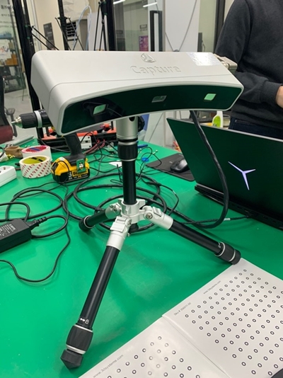
This is a 3D scanner model called CAPTURE from 3DSYSTEMS. Recognize the shape by rotating the model to be scanned 360 degrees.
This is a spinning wheel. If the bottom is fixed, turn the board and take a picture while holding the position. The white bat next to it is like a background without any reflection.
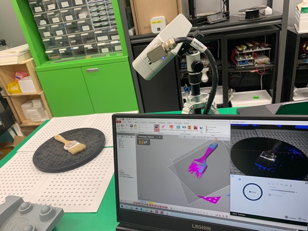
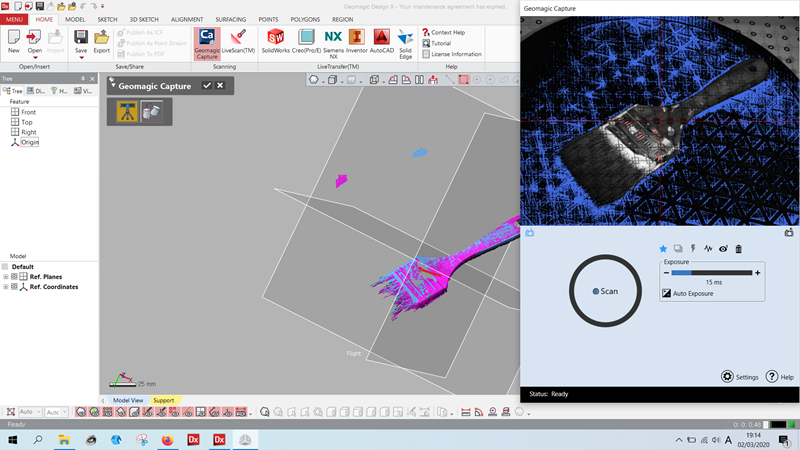
This is a picture showing how to work. I tried, wondering if I could scan the front of the brush well.
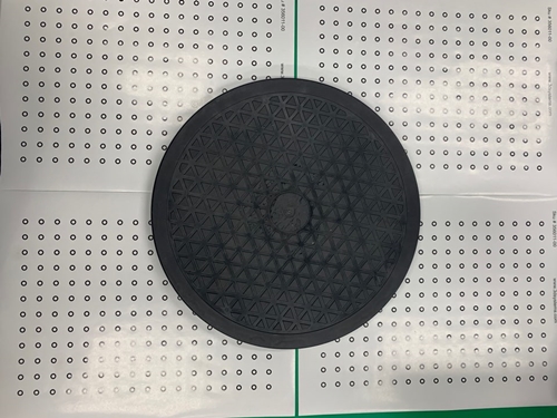
For 3D scans, it should be set up so that the background can only be scanned on a black circular plate.Create continuously overlapping scans. Scanning by slowly turning the angle (about 10 degrees) and repeating the process again to make the shape perfect. Occasionally, the scanned screen turns off, which requires turning the angle inside the software.

The above brush was missing the scan file, so I tried a new 3D scan. It's an application called Bellus 3D and you can download it for free!
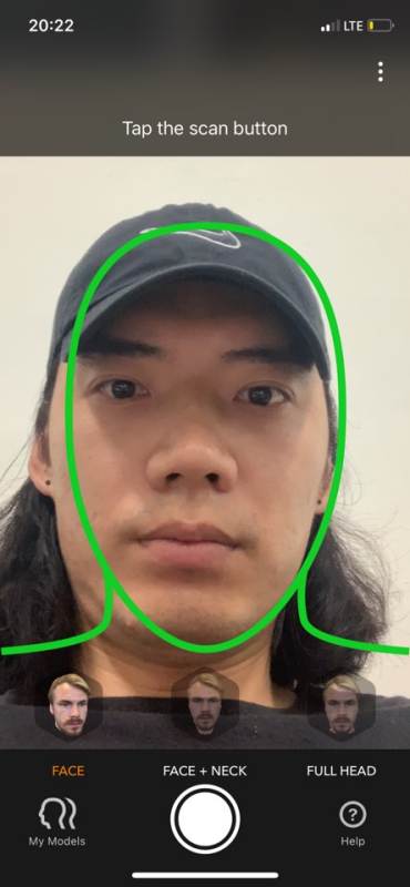
To scan the face at first, put the face on the green line as shown in the picture.
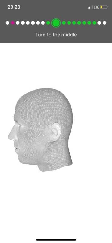
Then slowly scan the contour of the face from side to side as you move on to the next screen. It is mostly similar to other 3D scanning methods. Slowly scanning each frame was of good quality.
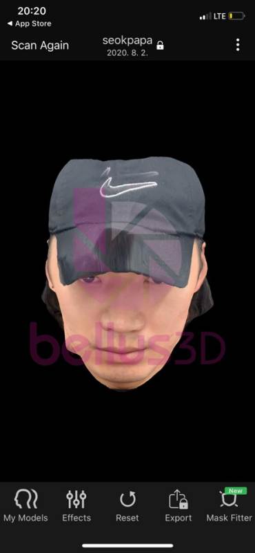
After scanning, there is a window that allows you to turn it in various directions.
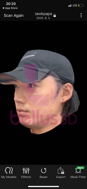
Check to see if it's scanned from side to side and from top to bottom.
Here is complete Scanning at our fablab(Jihwan's page) : Link
3D Scanning STL files : Download