3D Design by Fustion 360
This week, I tried to design using a fusion so that I can make both mold and casting.
Then, I tried to make a toolpath using Vcarve software, and after milling, I tried to make a mold and casting by selecting from some of the materials that I had checked during the group work.
Here is our group works : week15
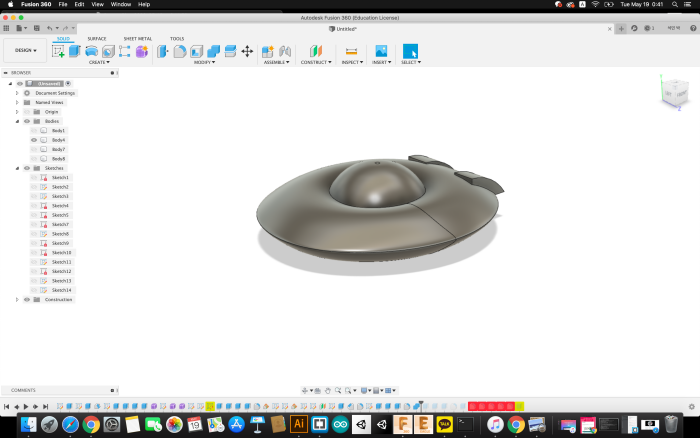
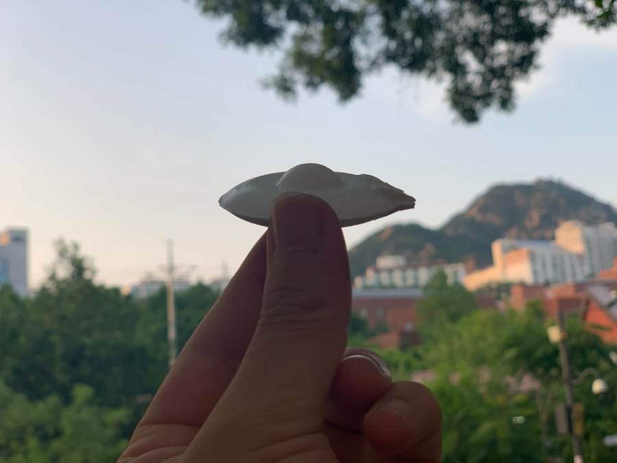
3D Model : UFO
I modeled for UFOs that float on the water. in fusion 360
Mold milling plan
● 145 x 85 x 37 Wax
● Check the End mills (Avoid collision with materials)
● Roughing Milling
● Finish Milling
● Use the Vcarve Running preview
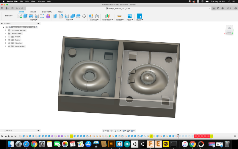
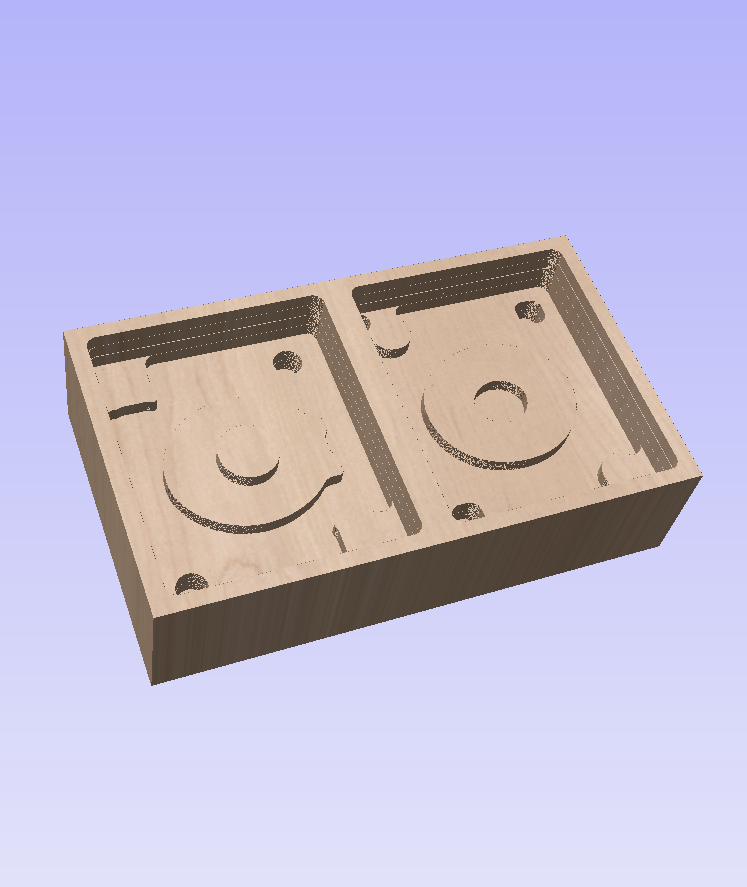
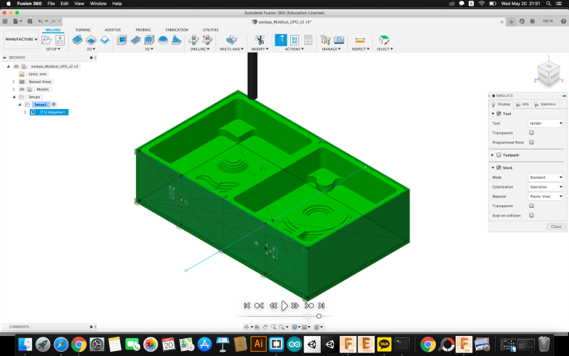
This is a 3D modeling of the mold.
Due to the large number of curved sections, ballnose end mill will be used, and dog-bones were also added to ensure that the top and bottom parts of the molds fit well.
To reduce friction when loading and removing moulding materials, 2degree draft angle is set.
the pour hole for casting material was modeled as 5 mm.

I used the Vcarve program and made Toolpath by exporting STL 3D file.
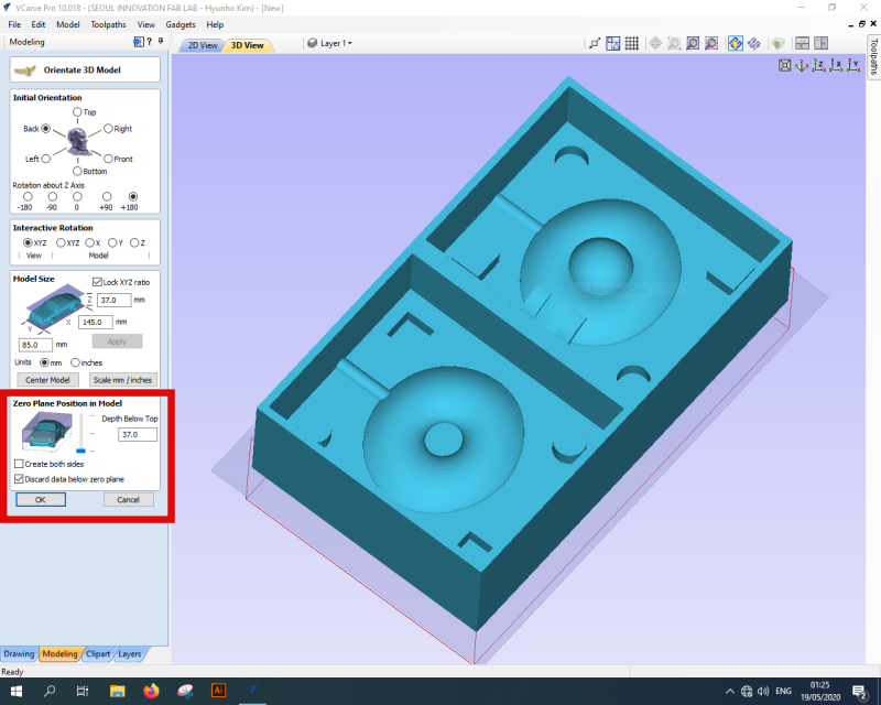
This is the first screen of when you call up a 3D file.
When I first called it up, the file wasn't exactly attached to the bed.
I could attach it to the floor through the top lotate and initial orientation.
Modeling size and Z-axis position can be set.
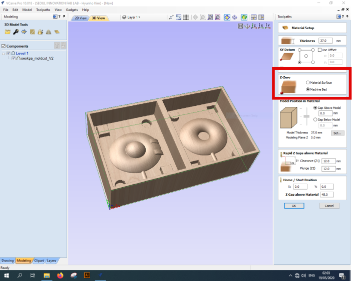
The next screen is a window for setting materials, and it is important whether the Z-axis origin is on the material or on the equipment bed.
It can cause a collision at the same time as it begins.
Don't forget what you've set up and set it up well before you work!
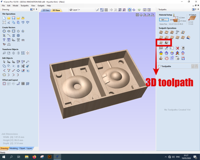
The top part of the 3D file is toolpath routing and finishing.
The part of the 3D file is toolpath routing and finishing.
First, we used the rolling toolpath 6mm end mill, and the finishing tool set the ballnose 3mm.
Toolpath preview
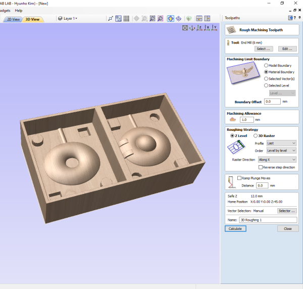
Roughing toolpath preview
● 6mm Endmill
● Running 31minuate
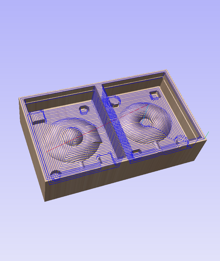
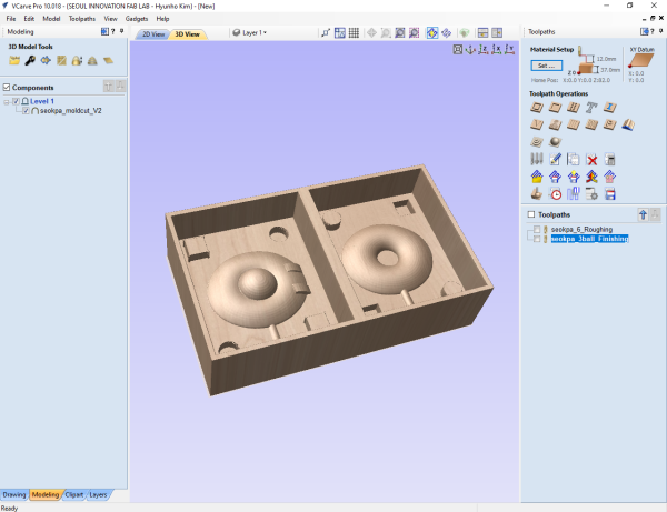
Finishing toolpath preview
● 3mm ballnose Endmill
● Running 37minuate
Use CNC
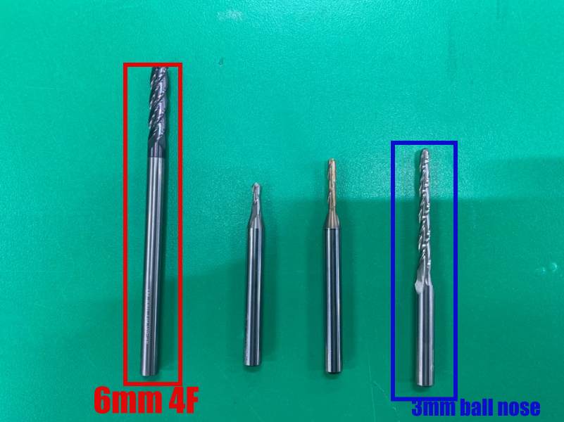
TI used one of the two endmills on the picture.
The reason why 3mm ballnose long wings are used is because of collision prevention. The reason why the left side 3mm ballnose end mill was not used was because the depth was deep and could collide with the wall, so the right wing was long.
Setting the boundering time is to reduce roaching and finishing time.
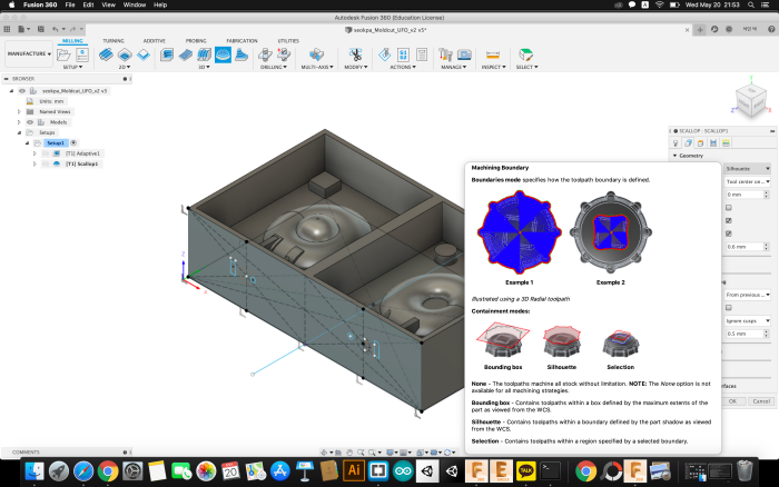
I also tried to set it up in Fusion 360 Simulator mode. The simulator was able to generate the end-mill setup and G-code immediately.
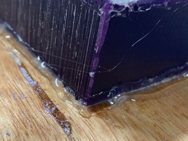
Fix Wax with a glue gun on the plywood board.
Here, the caution is to adjust the vertical level well and use the glue gun.The wood below used to hold wax used waste wood thrown away from the wrap.
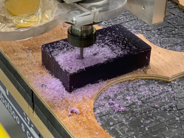
The reason why I used Shop Bot was because We have ER16 collets in that size (see picture above). Rough 6mm 2F downcut took 37 minutes and Finishing 3mm ballnose took 1 hour and 30 minutes.
Because the design of the mold I’m going to make is 20 mm deep and the length of the other ballnose field is short, I used the end mill of the picture. That end mill has a blade length of 30mm. I fixed follwings !
Wax, the material of mold making, can be melted and reused. Therefore, chips created after milling can be collected and melted into slow cookies or large bowls for reuse. The storage method should be stored in a sealed container so that impurities do not mix. When impurities are added and melted, it is difficult to reuse wax.
And I think it would be better to work in a working environment where the dust from wax may not go out than in an open environment. In a situation where air is not coming out of the end mill as it is now, I thought that the wax might melt as it milled by the fast rotating end mill and affect the outcome. Therefore, I think it is appropriate to manufacture from a covered equipment in the following tasks. The spindle rate was set to 10000 RPM and the feed rate was set to 750mm/min.
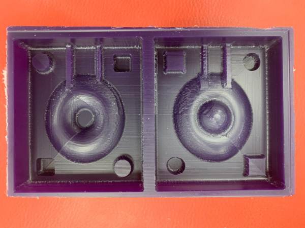
This is the final appearance after milling. It looks like we need a little more finishing.And if you look at the picture above, I milled the holes into two and redesigned them. There must be an inlet and a hole in the air to make more details of the result.
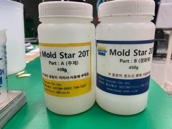
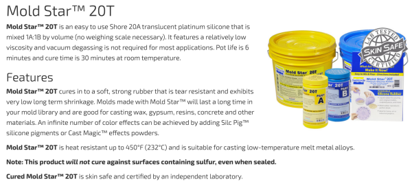
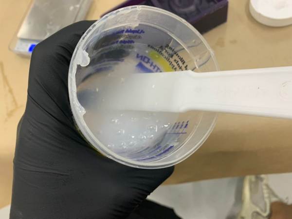
Mold Star 20T was used as silicon for mold production.
Mold Star 20T is difficult to use vacuum equipment because of its short work time but short time.
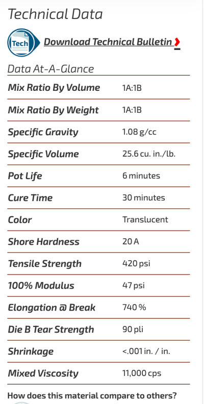
The above are data sheets and safety points.Please refer to
●mixed 1A:1B by volume
●Pot life is 6 minutes and cure time is 30 minutes
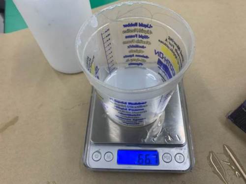
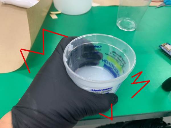
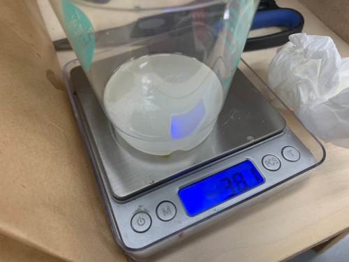
It needed 66 grams per part. It used 132g because it was 1:1 ratio was 1:1.
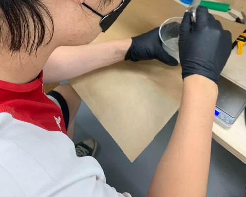
After adding part B, check the pot time and stir well.
Since vacuum equipment was not available, cups were removed with some force on the floor to remove any air bubbles.
I don’t have enough time, so I have to work quickly to use my pot life well.
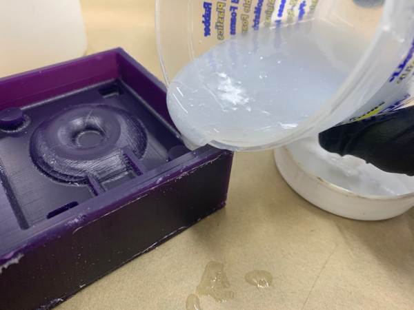
And then pour it into the mold, slowly pouring it over the wall to make the most of the contact with the air, rather than pouring the ingredients too high.
was a little short, but I waited for Cure time. I checked.
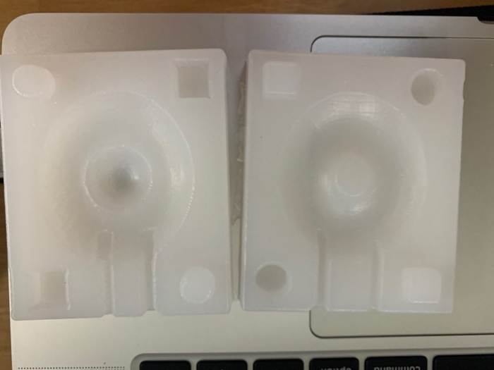
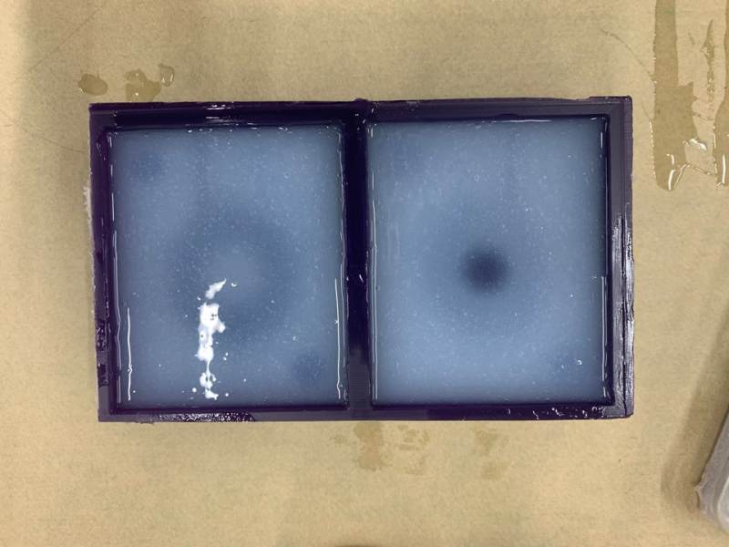
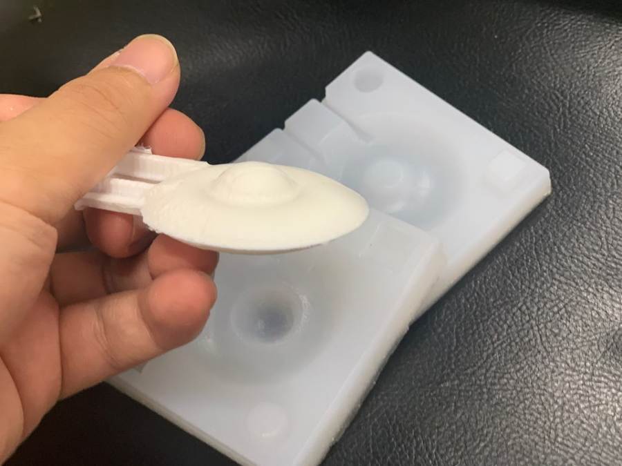
This is the result of taking out Mold after about one o'clock. It is fortunate that there are no cases where the amount is insufficient to fit each other.
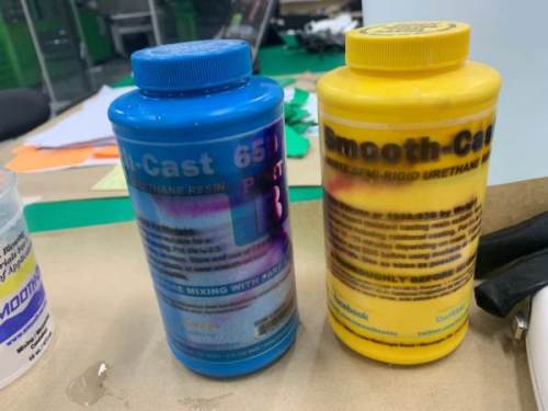

This time I used Smooth Cast 65D to cast my UFO.
This material has a shorter pot life and a shorter Cure time than the previous silicon.
And when you actually mix it, you can feel a lot of heat generation.
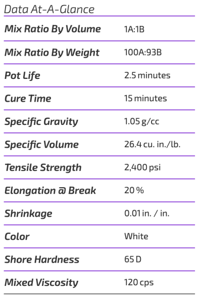
●mixed A 100 : B 93 by volume
●Pot life is 2.5 minutes and cure time is 15 minutes
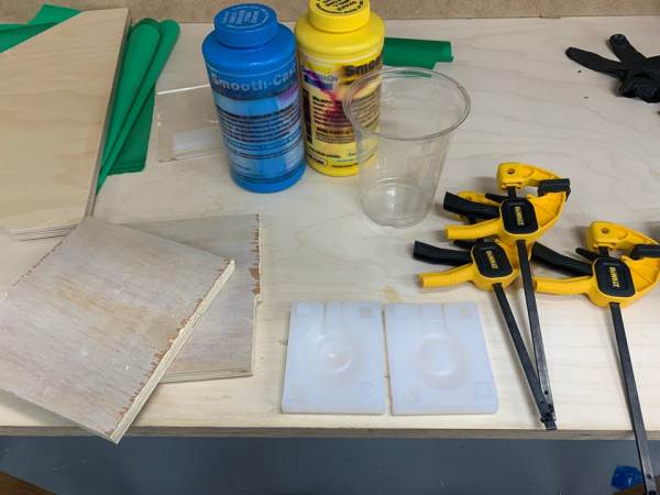
A ssmall clamps and a wood backing were prepared to support the mold before work. Because it was a silicon mold with less rigidity, it needed materials that could be fixed.
This is what it looks like when the mold is overlapped. I had to put it in slowly because the filler door was designed small.
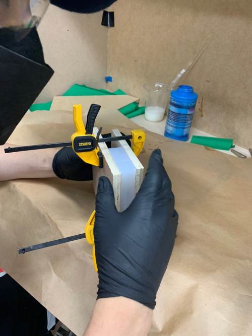
As shown in the picture, I fixed it with a clamp and then mixed the ingredients. The pot life was very short, so we had to efficiently arrange the work flow.
This time, the total was 50g and the top was part A (32g). It's a little over, so add more part B.
Stir quickly due to short time, then pour into the mold before hardening.
Because of the short working time, I could feel the heat occurring and hardening quickly.
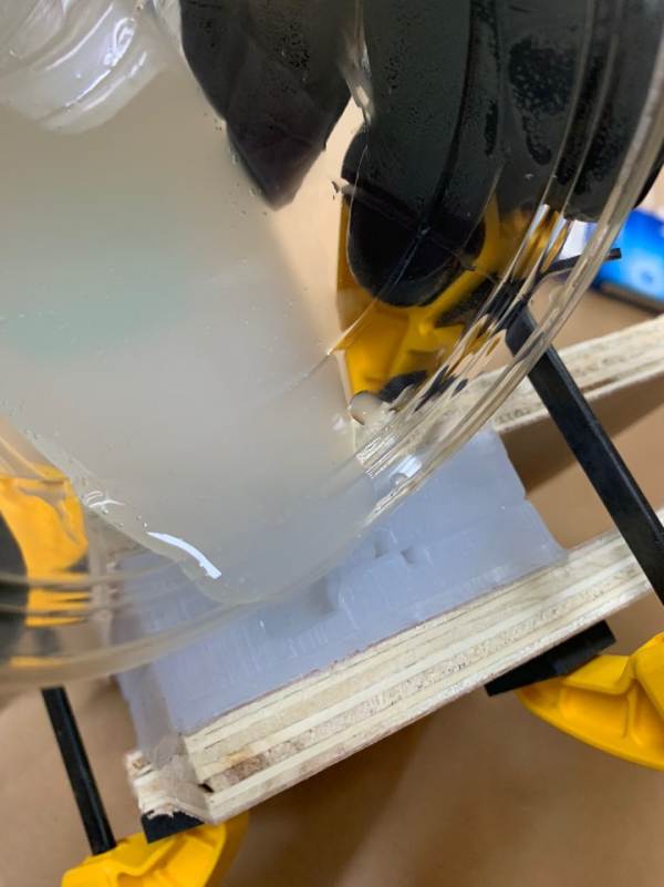
Pour slowly over the filler hole.
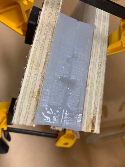
As time went by, I was able to find a little swelling. Air holes were also filled with materials.
Five minutes later, it swelled up even more, as shown in the picture. It seems that the volume expanded as it hardened. I wonder if the results...
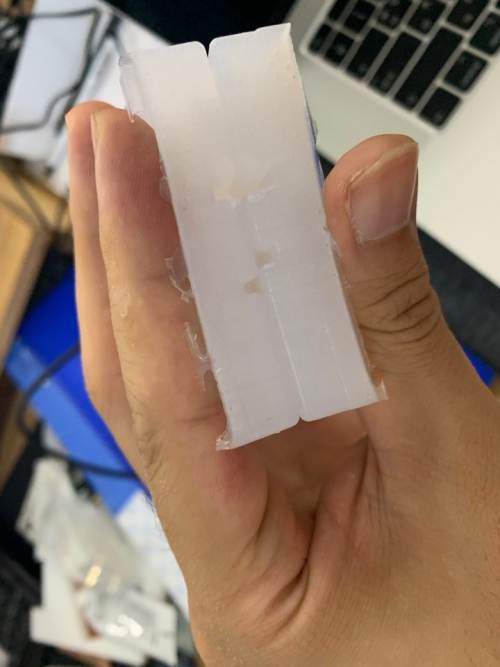
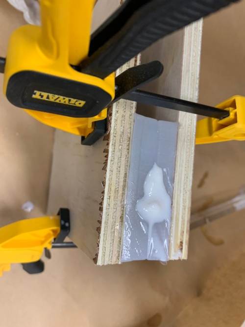
About half an hour later, I took out the ingredients from the mold.
There was no inconvenience in taking it out, but it was a little overflowing as shown in the picture, so it was cast in an unnecessary place.
I learned that I should be less swollen next time.