
Week 3
Computer-controlled cutting
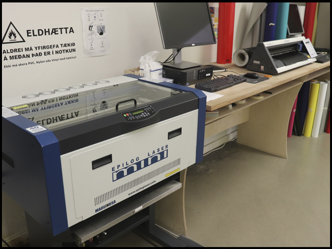
>Turn for the cutter machines.
The vinyl assignment consists on design an illustration and set it for the vinyl printer.
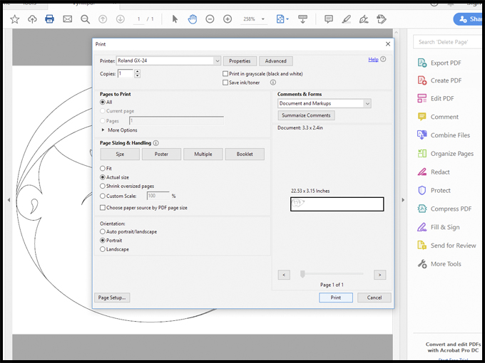
In this case, the printer set in the lab is the Roland GX 24. The steps to follow are:
- Draw on Inkscape the figure, cartoon as you which. My choice was the face of one character called Vicentita.
- Be sure that the lines that need to be cut are in 0.02 mm.
- Keep like a PDF.
- Choose the color and kind of vinyl. Set it in the printer. Like you can see on the second picture below for this assignment was black.
- Set the printer speed on 20 cm per seconds and power of the cut 100 of pressure of the knife.
- Put the vinyl straight and fit it the wheels properly.
- Check the roll setting move and find the origin or position 0.
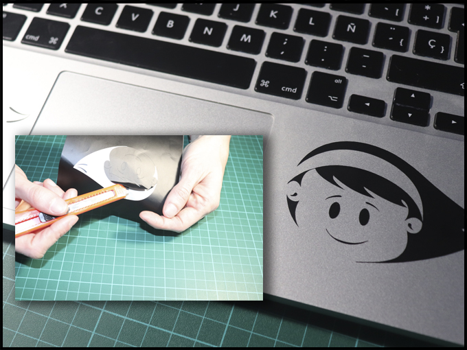
Once you have the print on your hand, be careful when you spill it out from the vinyl to paste it on the main body, like I said before, it can break.
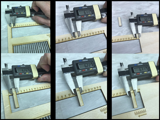
The other task of the week is divided in three part:
1. The group assignment where we will check the cutter machine of the lab with the same pattern and material: wood 3 mm.
To do this assignment the Iceland group will test the machine of each lab and see the results each of us get. Like you can see on the picture, the design consists in a rectangular piece divided in 19 small pieces of 6 mm. each. I set my machine to print on plywood of 3 mm.
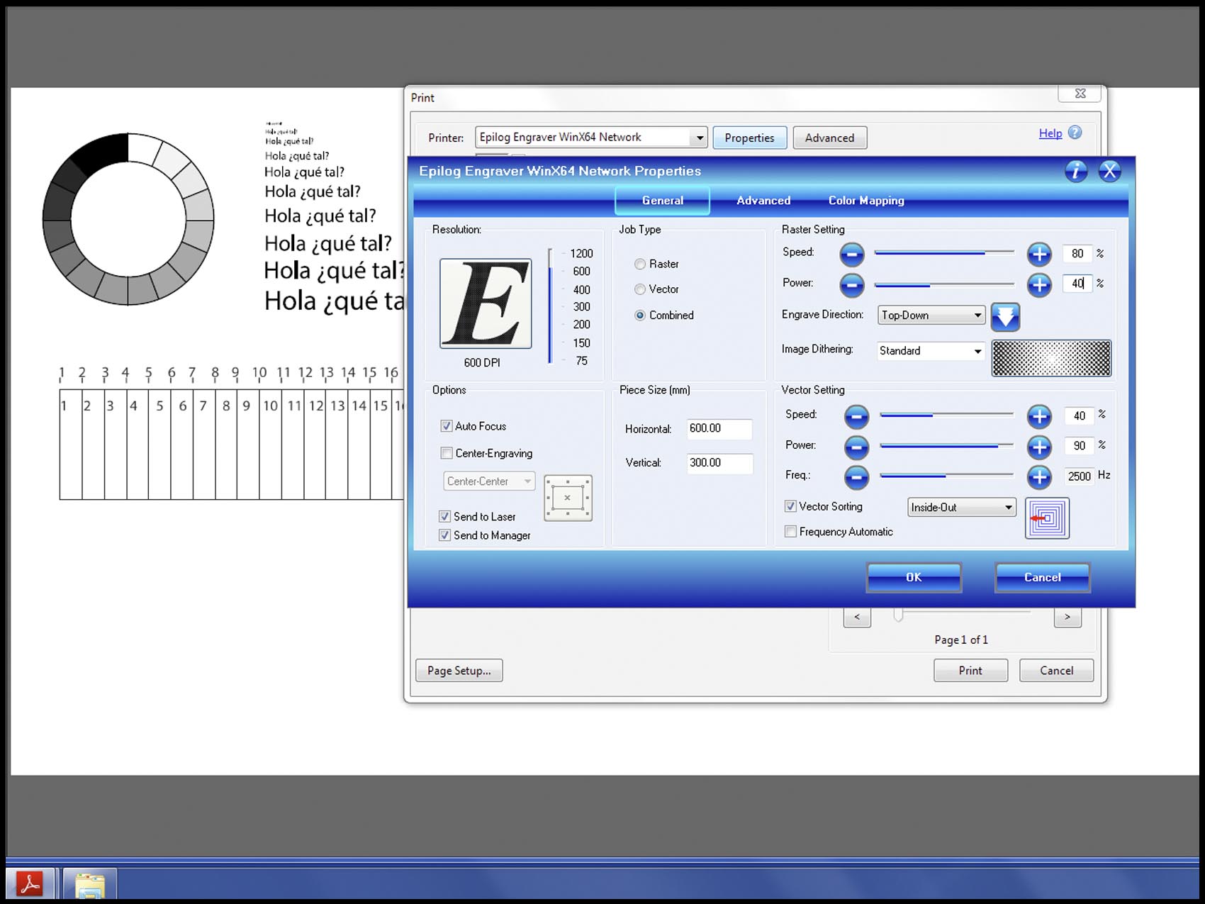
The next picture shows the setting of the laser cut to rater and vector the material. In this case, was plywood of 3 mm. The Epilog Laser mini that is on the lab is working with autofocus, so that option hast to be marked. After that, it is necessary to follow the next steps:
- Combined because it is going to raster and cut.
- Size. For this one was 600 per 300 mm even though it was used just 297 per 210 mmm.
- Raster speed of 80% and power of 40%
- Vector speed of 40%, power of 80% and frequency of 2500 Hz. The right vector setting for this kind of material is 14% of speed, 100% of power and 1000 hz. of frequency. With this you will be sure that is easier to cut the pieces.
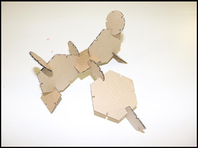
2.Individual assignment where we need to design a construction kit using parametric and cut it on cardboard.
This was my first experience with parameters. So, at the picture below I am showing where to find the setting to create a parameters measurement to use in your design after.
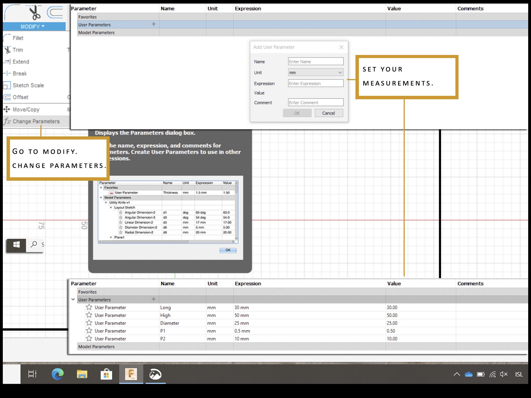
At the beginning I said to myself that I will never use it again because it had not sense for me, but not so long I used it after this assignment and I started to understand why the people say that when you use parametric once, you will not want to come back to the normal design.
The point is to use the parameters when you are going to use different kind of measurements and you do not know if you will need to change it after. I mean, if for example I have a size of 0.5 mm for a small detail on my design but, I realize when I finish all that it is not working, and I would like to put 0,3 mm more I just need to go to modify and change parameters. Then all the sizes will change to the new mesuarements.
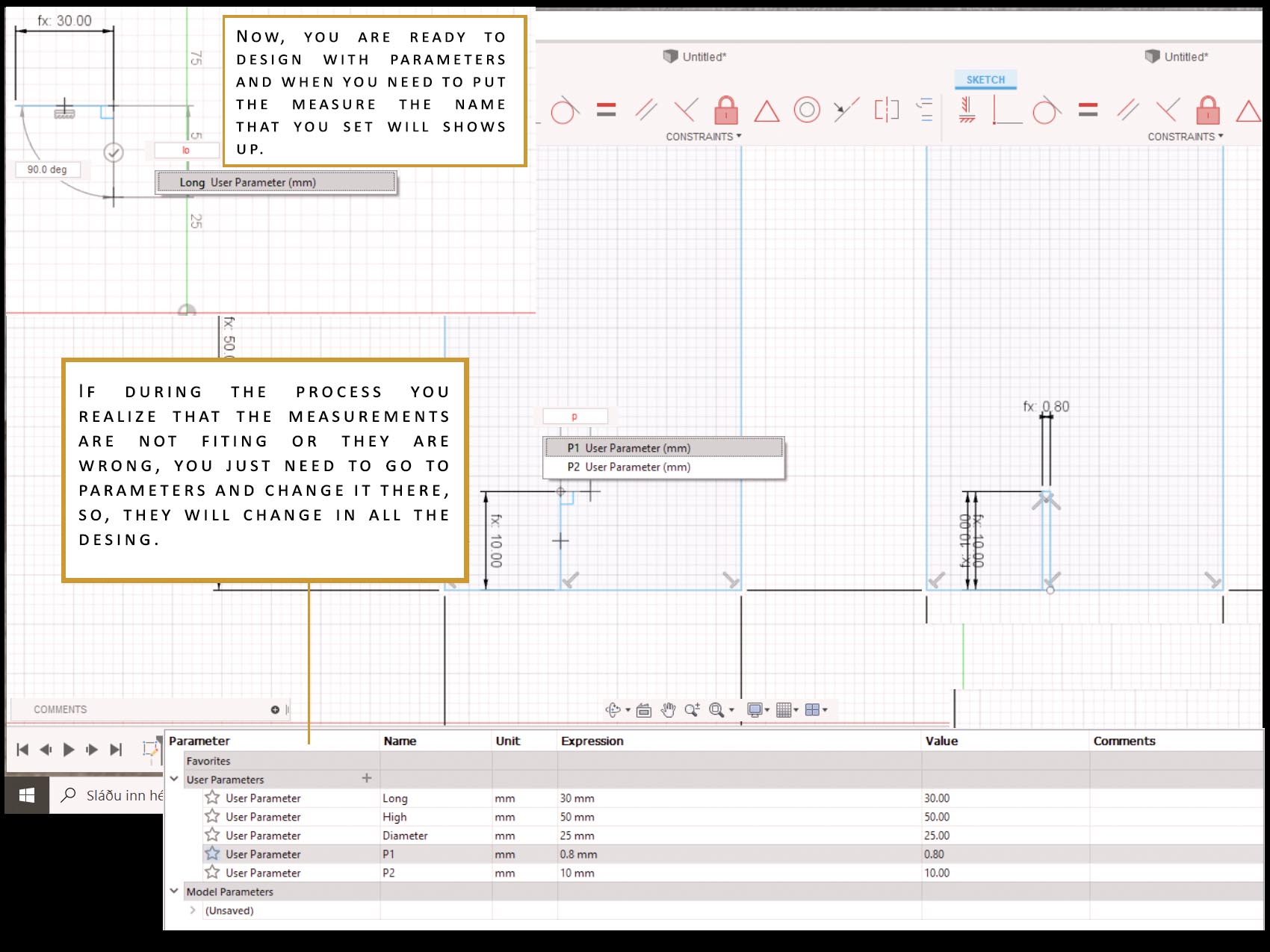
It is important to not delete the guide constructuon or the parameters will not work.
The principal advantage is that you will save time. With this technique I design the assignment of the "Construction kit", like a first experiment with it, it is worthy, but I will need to get into it to be able to use it well and with all the benefits that you can get from it.
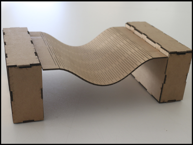
3. Extra assignment where we design a flexible construction with a pattern. Also using cardboard of 2.5mm.
During this assignment I stuck a couple (million) times because I was not sure about what to do or show. I was looking for pattern to use, that gave to me ideas for my final project. When I got the design, I forgot how to save from fusion 360 to Inkscape. At the end, I found it
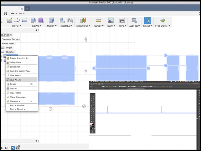
Once you finish all your designs and everything is right and ready to send to the cutter / laser machine, it is the moment to export the file from fusion360 to illustrator or inkscape (whatever you use). For that, you need to:
- Go to the sketch.
- Click right button.
- Safe as DXF. file.
Now you have a file compatible with the other programs. However, I would like to make a point to: when you export from fusion360 and open on Inkscape, sometimes the design has more line than supposed to have and it is necessary to clean it before printing it. Also, take a look if it is some gaps or lines that are not closed.
After that, prepare the lines to be able to cut for the laser (0.02 mm) and safe as PDF. file.
Depend on the material that you are going to cut and the laser machine that you are using the setting of raster and vector (or both), and also the power, frequency and speed can change.
For the last two assignments: construction kit and flexible test was used cardboard instead plywood. When the material to use changes, the setting of the laser could of that the setting for the laser cut must change. Like it read in the picture below, it needs to set just the vector part to be able to cut the cardboard: speed of 40%, power of 90% and frequency of 2500 hz.
It is important to know how much kerf the laser has because this mean that the material used will lose some minimum part and that can damage the final art. In this machine, the kerf is around 0.08 mm in both materials. The kerf can also change depend on which material you use.
Files
Vynill
Cutter test. Illustrator
Construction kit. Illustrator
Construction kit. Fusion360
Bridge. Illustrator
Bridge box. Fusion360
Patterns. Illustrator