Electronics Design
Week 06
Machines and Materials
Softwares
Files
Group Assignemt
During this week we started designing (re drawing) the echo hello-world board, Attiny 45, since is the one we have at the lab. We milled it, soldered ir and finally programmed it.
Individual Assigment
Redraw an echo hello-world board,
add (at least) a button and LED (with current-limiting resistor)
check the design rules, make it, and test it.
I followed the next steps to make my hello-world board and added a led and a bottum.
1- Download Eagle (there is a free vesrion)
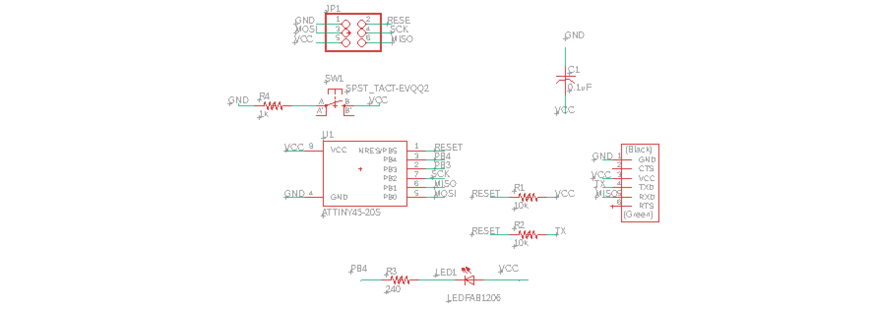
2- Click "add parts" and add the parts following the hello-board reference.

This is the list of what I used:
- Attiny 45
- Led
- Resistor 240, 10k, 10k, 1k
- 2x3 pin holder
- Capacitor 1uf
- Push button
- 1x6 male pin header
3- Not all the components are in the library so you can download it from here and add it to your library.
4- To add a library you click -> Add parts ->Open Library Manager-> (the name of your new library) -> use.
5- After adding all the components is time to start conecting them. To do so click on "net" and you can either draw a line to conect manually or write a name with the "name" option. After adding the same name to 2 parts it will automatically conect.
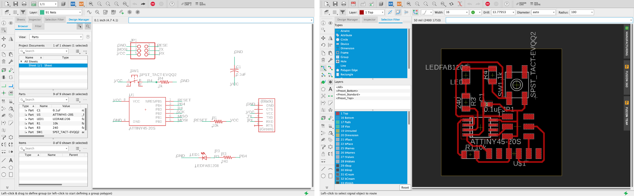
6- When done with your schematic click on "Generate/Switch to board" and start routing.
Note: Avoid 90 degrees edges, line width should be 16, rotate and organize the components before you start routing.
7- Follow the yellow lines and start manually routing, routing might take some time.
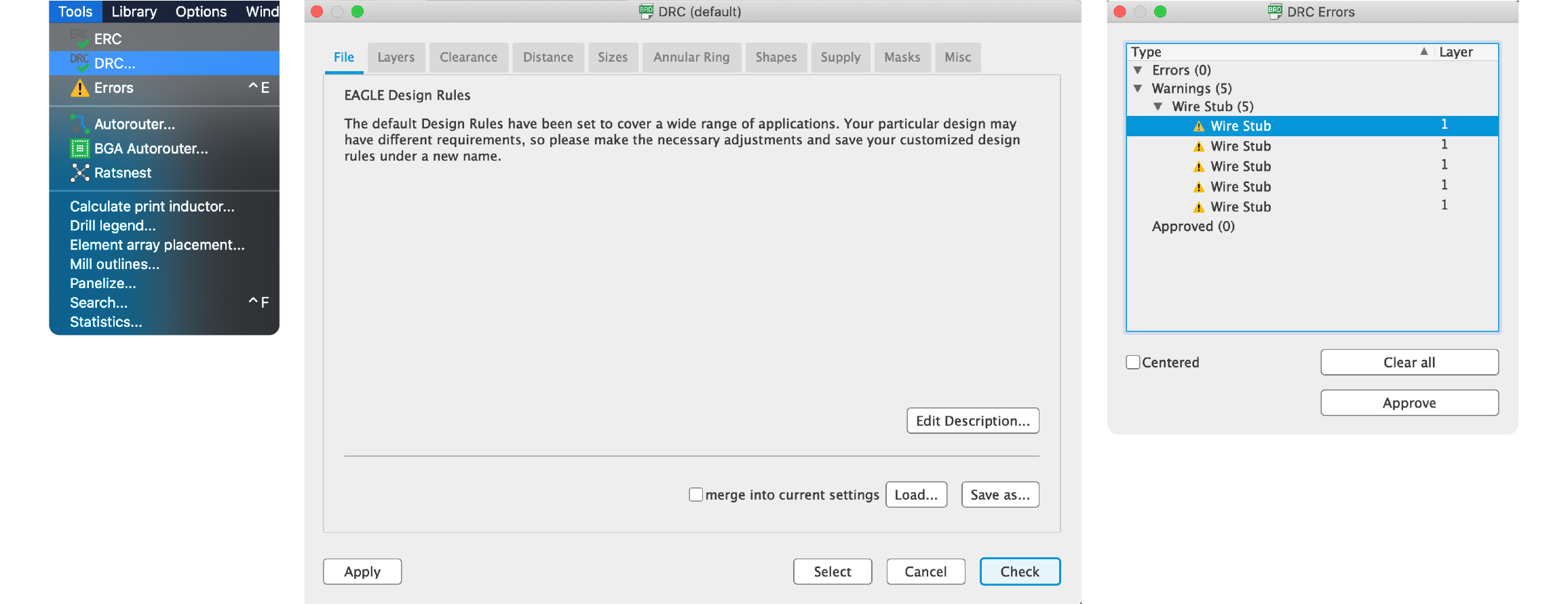
8- Make a "Design Rules Check" ->tools ->DRC -> Check .
9- Save.
This was my first attempt but its WRONG! so DONT copy it:
( A tinny was not properly connected)
Second try (corrected)
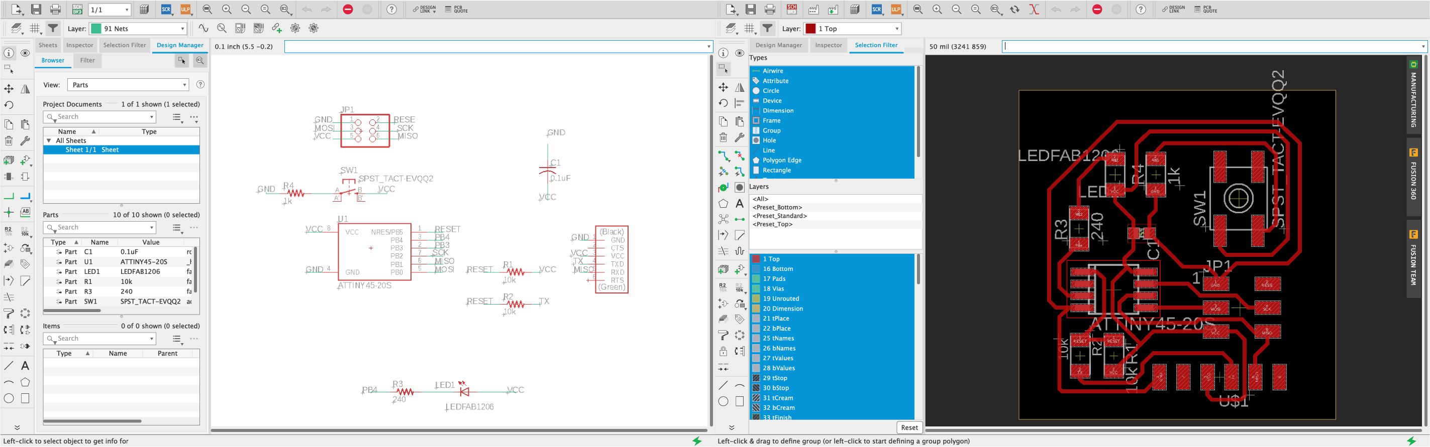
Before perparing the files for milling we run a DRC (Design Rule Check):
- Tools -> DRC -> Check -> fix manually one by one.
Prepare the files for milling:
Note: If you prepare them from Mac it might lose the domension, it is better to open your file in a Windows computer and prepare the files from there.
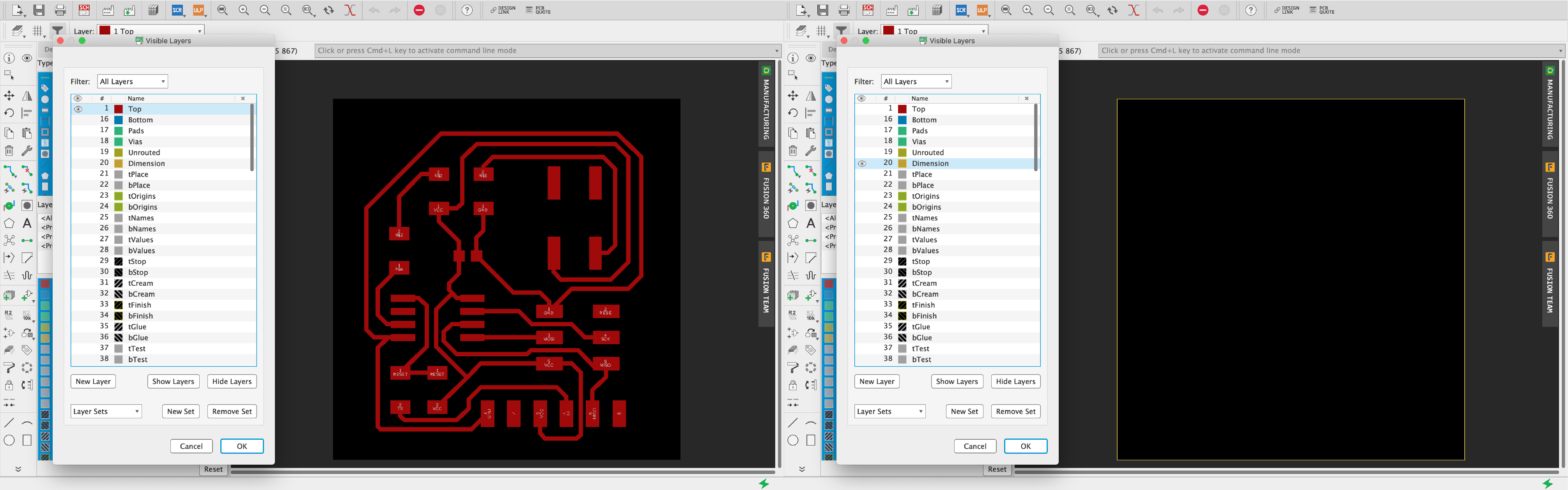
1- View -> Layer settings -> Hide Layer -> show "top".
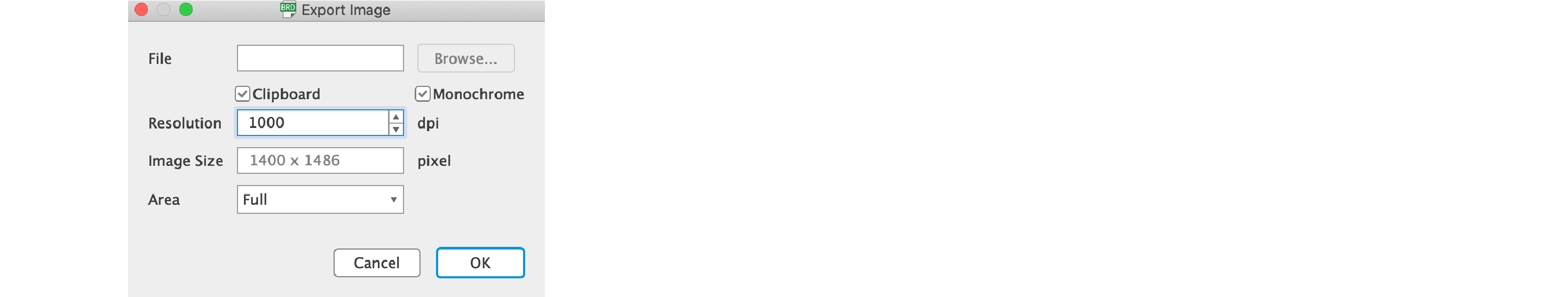
2- File -> Export -> Image
Resolution: 1000 Monochome.
3- We do the same for the dimensions: View -> Layer settings -> Hide Layer -> show "dimension".
4- File -> Export -> Image
Resolution:1000 Monochome.
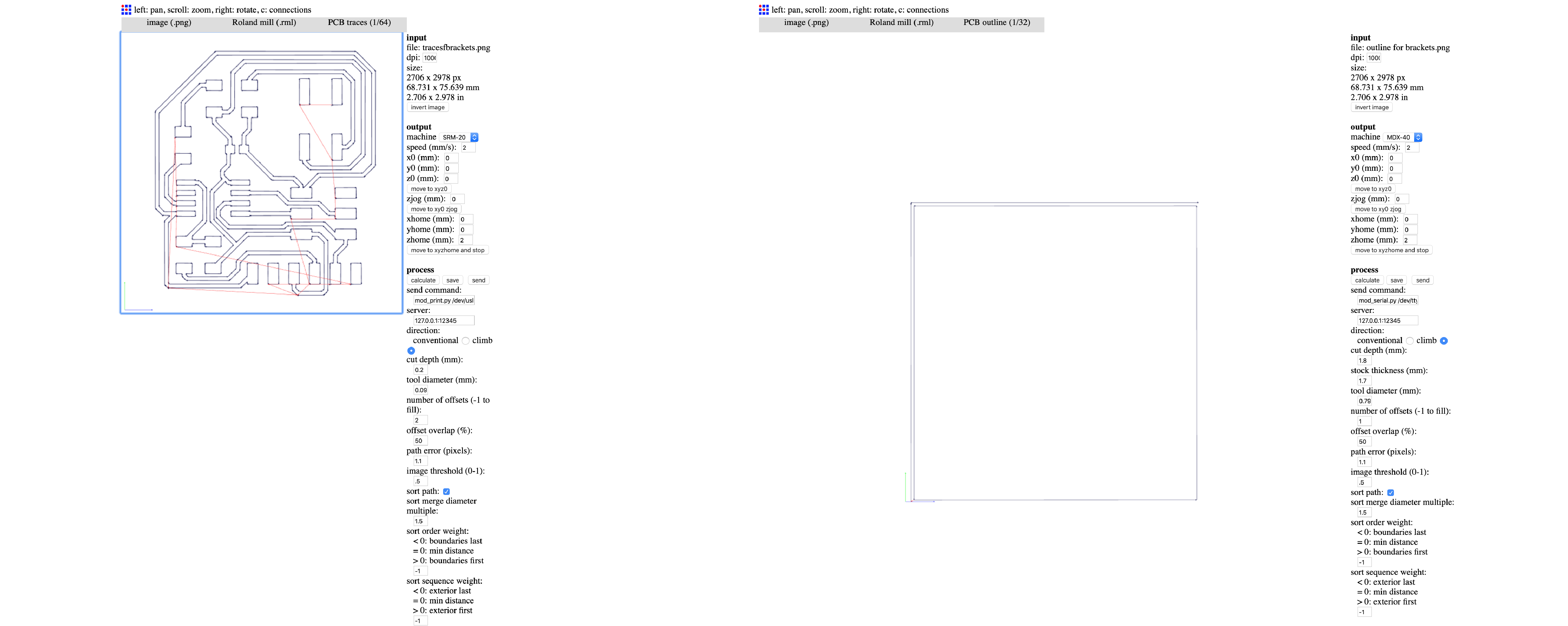
Open Fab Modules
For traces and outlines these are the settings we use at the lab:
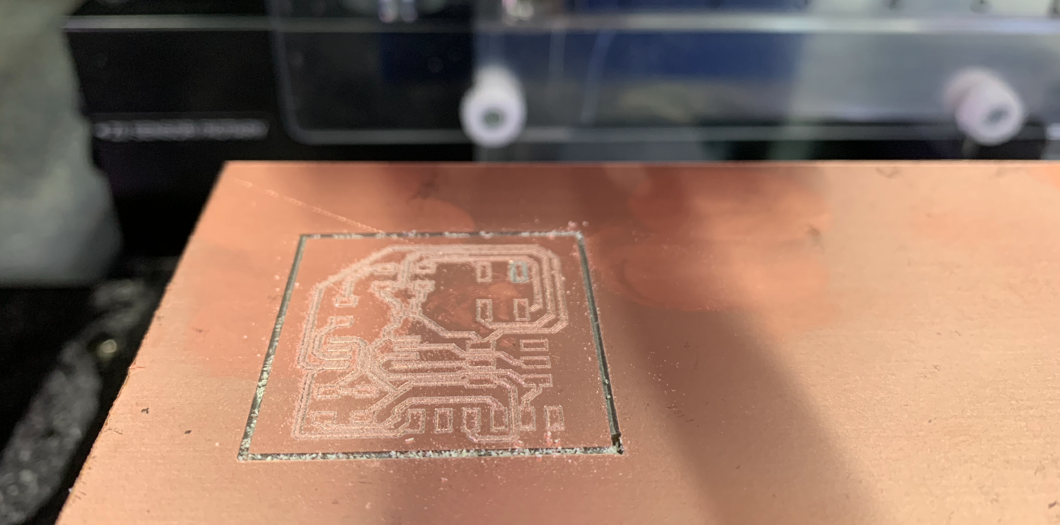
Milling process
As explained in my past assigments, we open the software for the milling machine (Roland 50 in our lab) we select the X and Y origin and make de Z sense.
In the software we click on output, select our file and it will automatically start cutting with the tool we last selected.
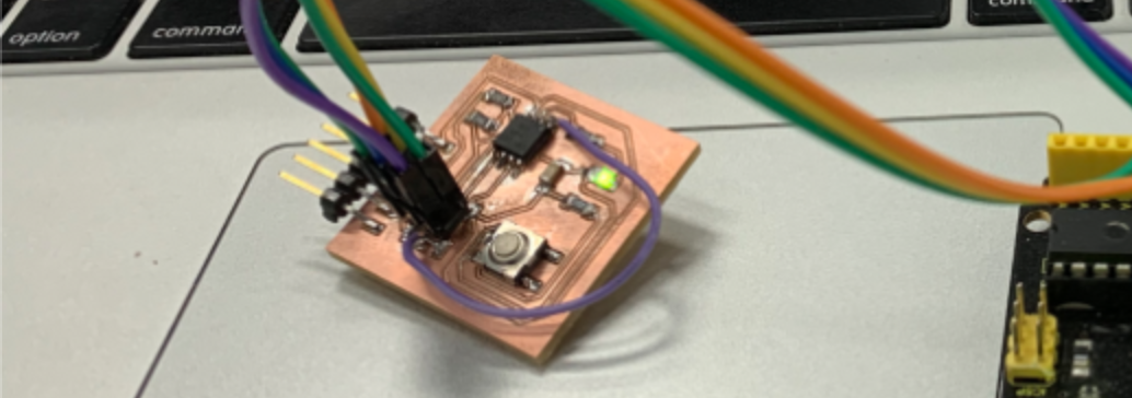
Here are the results of the soldering process:
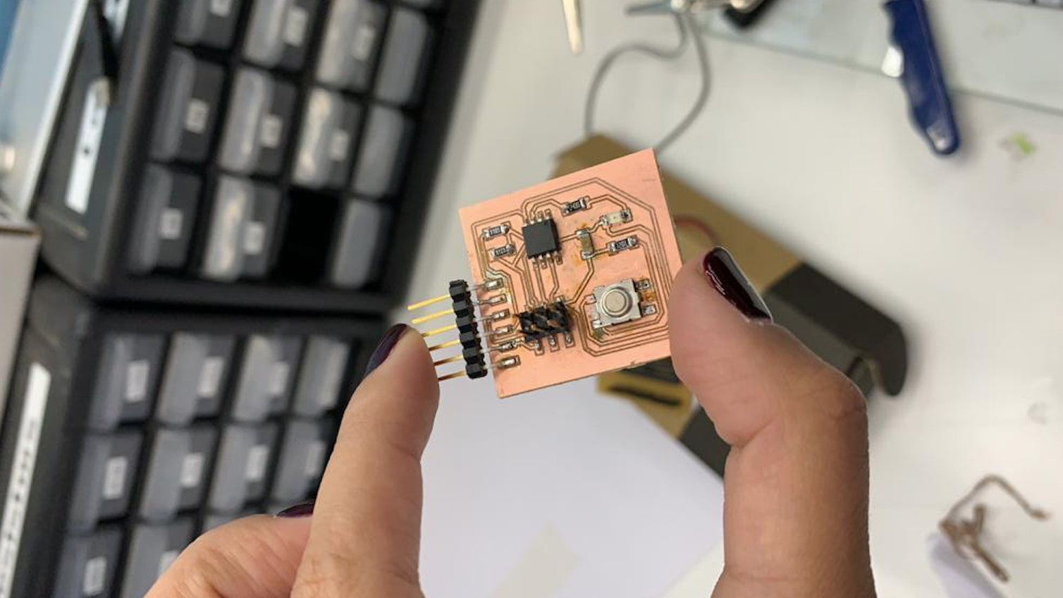
I checked it was working by making all the conexions. In Assignment 8 you can see step by step how to program it and connect it.
I encounter some problems, even tho it's all conected as it should for it to work, but, there was a missing conexion to the pin out. I had to solder a wire from the pin out to the line (attiny leg) so I was able to program it. Glad that was the only problem and after conecting it, it work completely fine.