- Individual assignment
For this week assignment. I decided to choose the HC-SR04 Ultrasonic Sensor as Input device on an LCD i2c Display.
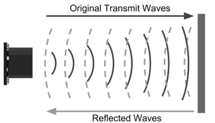
How Ultrasonic Sensor Work?
Ultrasonic sensors work by emitting sound waves with a frequency that is too high for a human to hear. These sound waves travel through the air with the speed of sound, roughly 343 m/s. If there is an object in front of the sensor, the sound waves get reflected back and the receiver of the ultrasonic sensor detects them. By measuring how much time passed between sending and receiving the sound waves, the distance between the sensor and the object can be calculated.
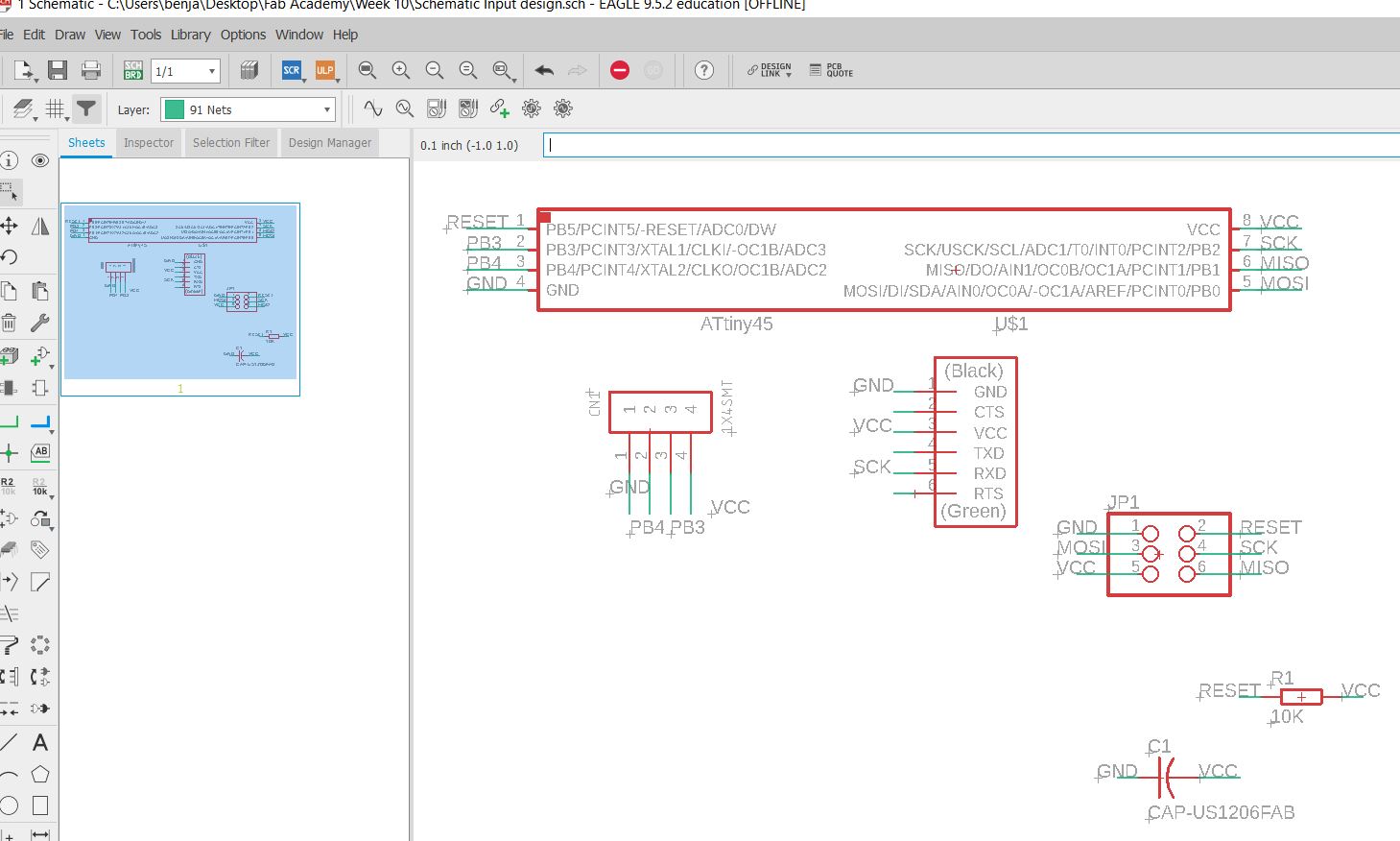
PCB Circuit Design
As a starting point I had to list down all components needed to draw the PCB. ATTINY45 was used, however i was not able to find the exact footprint in eagle software.
so I had to upload the library that provides the exact footprint.Once all components were specified, the connections were made as shown below
Download link for fab Library
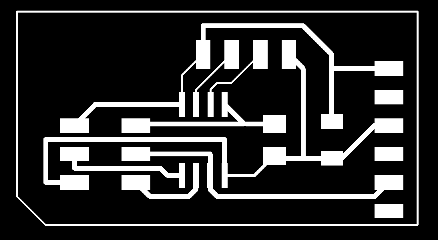
- After creating the connection, next step was to start the routing process. The result was as the following
Click on text below to download Eagle File:
- - Ultrasonic Sensor Board Eagle schematic folder
Programming and Testing
- At this stage I had PCB design ready to be uploaded to the Roland machine and produced. However because of COVID-19 I did not have access to the Fablab and it was very difficult to perform the PCB production and Soldering.
Fortunately, I had the option to use the Home electronics kit that was provided by our Lab instructor. Programming the Arduino was very fun and much simpler than programming the PCB.
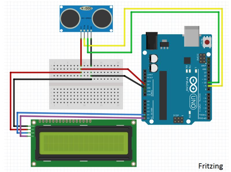
Below shown the list of items I used:
- Arduino KeyStudio
- LCD IC2 Display
- connecting wire and USB wire.
- HC-SR04 Ultrasonic Sensor.
I have made the connection between the items as the shown schematic.
- Once the arduino connection was made, the next stage was to start programming the board. I made multiple researches on the Internet about the programming process, I have added new liberey which was found already in Arduino IDE software. Below shown the Code used to operate the senso, including comments with explanation of the code.
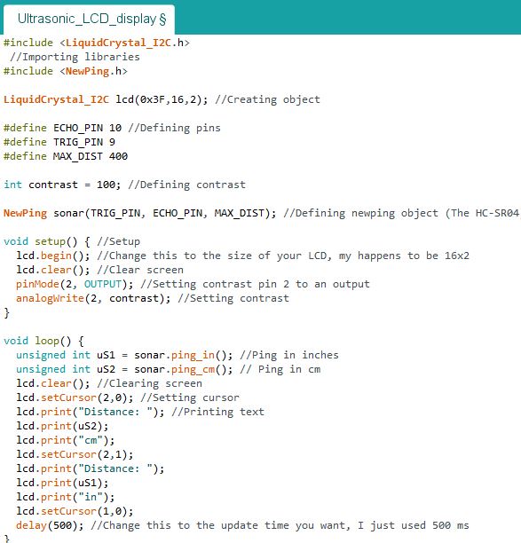
Click on Link below to download Code:
- - Ultrasonic Sensor + LCD Disply Arduino Code
- Finally Check the video below shows the demonstration of Input device testing for both Sensor and display on LCD screen