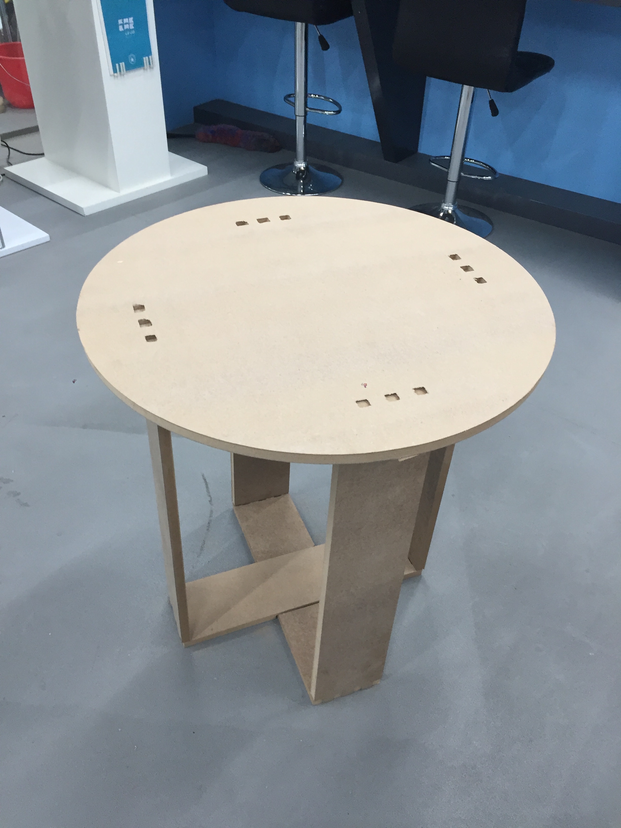
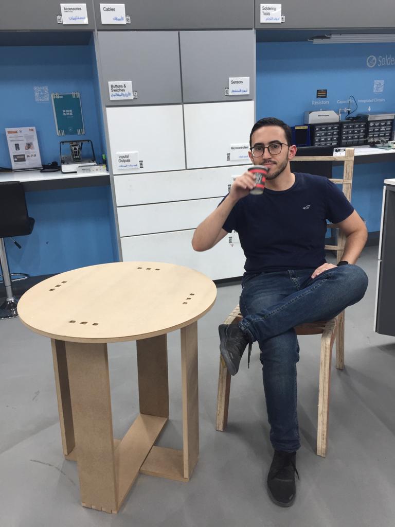
The assignment of this week was to design, mill and assemble something big. I have decided to design and build a Tea Table. The table was designed using Solidworks and milled using CNC Shopbot machine. A detailed explanation will be presented below showing the procedure of using the CNC machine and brief explanation on how the Table was designed.
The Machine Description:
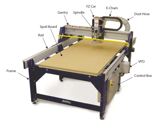
ShopBot CNC tools is a fully 3D capable, which means that moves are made smoothly in 3D space using diagonals and curves. Full 3D CNC involves both designing in 3D and during cutting simultaneous CNC motion in x, y, and z axes. The CNC cutter tip follows paths at 3D angles or in 3D curves in order to mill or curve complex shapes into the materials.
Machine Specs:
Model: PRSalpha 96-48. Cut/Movement area: 2.49m x 1.27m x .2m Footprint: 3.05m x 2.01m x 1.70m Step Resolution: 0.0127mm
Machine Preparation.
The first step that was done before designing and cutting was preparing the Shopbot. Below shown the steps to prepare the machine for operation:
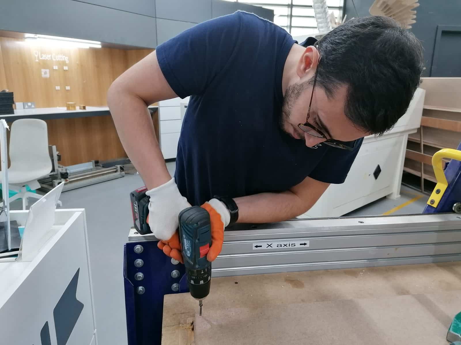
1- Material Fixation. The MDF 18 mm sheet was fixed on the spoil board using power drill and screws, as shown below.
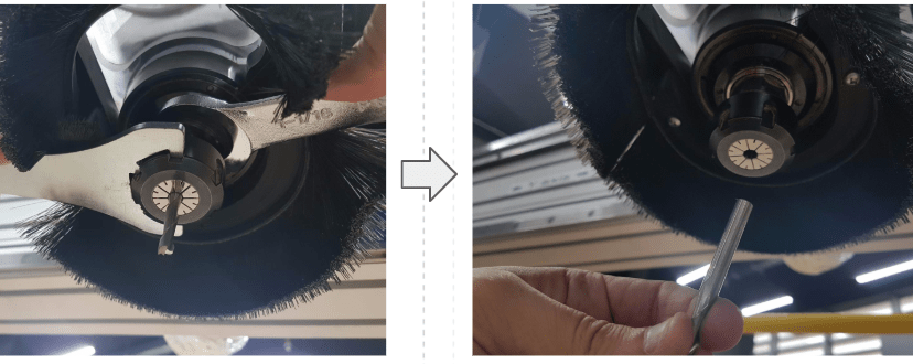
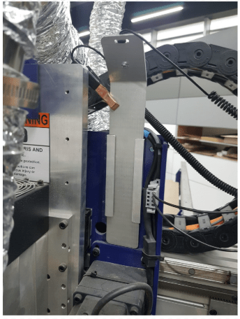
2- Check bit, the bit inserted in the spindle was checked and confirmed that it fits the cutting purpose. In this case it was needed to be changed. Shown below process of bit changing
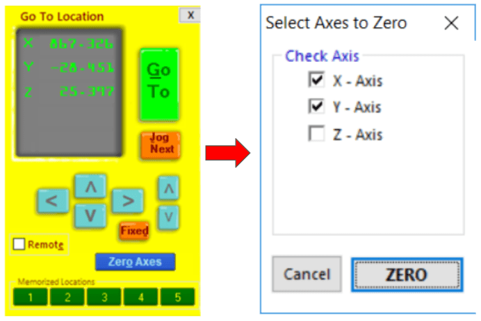
3- X, Y, Z calibration, to Zero the CNC machine axis we had to deal with X, Y axis manually then Zero the Z axis automatically. To Zero the XY axis the spindle had to be moved using the arrow to the location needed for cutting
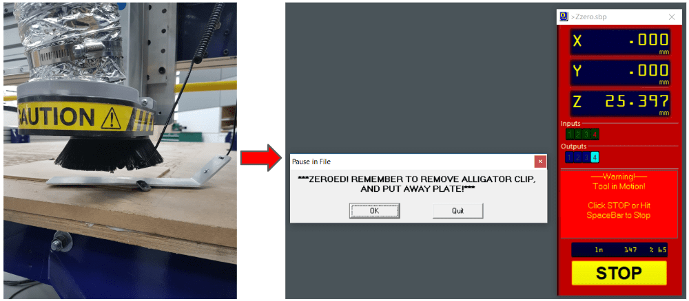
To Zero the Z axis the calibration plate had to be used. Shown below the calibration plate.
The process was to place the plate under the spindle bit and attached the clip to the collect nut. Then so to the ShopBot software and click OK to see the spindle moving down until the bit touches the plate.
At this stage the machine is ready for milling. Then the process of designing started using Solidworks.
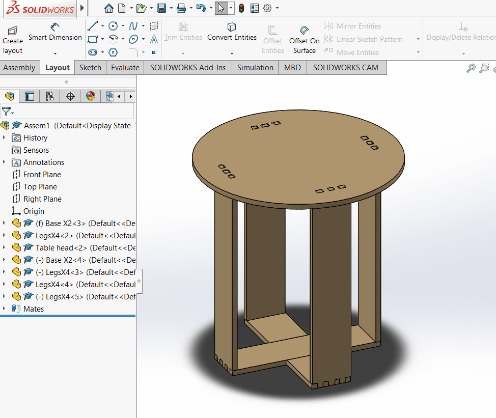
Wood Table 3D Design
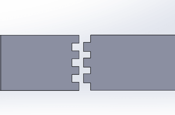
Solidworks was used for designing. It was the first time to create a design for wood cutting purpose, so learning about type of joints was important. For my design I have used finger joints, which are also known as comb joints, which made by cutting a set of complementary, interlocking profile in two pieces of wood and then connected.
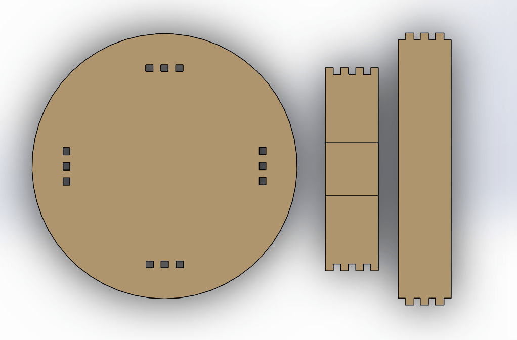
All parts were sketched 2D as shown below.
Then 3D assembly folder was generated and parts got conneted using the mate option.
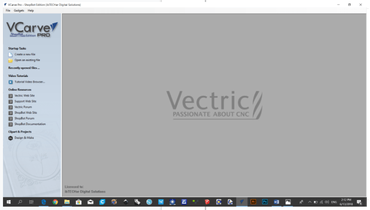
Once design was completed, all parts were saved as .dxf files and uploaded to the VCarve Pro cutting software.
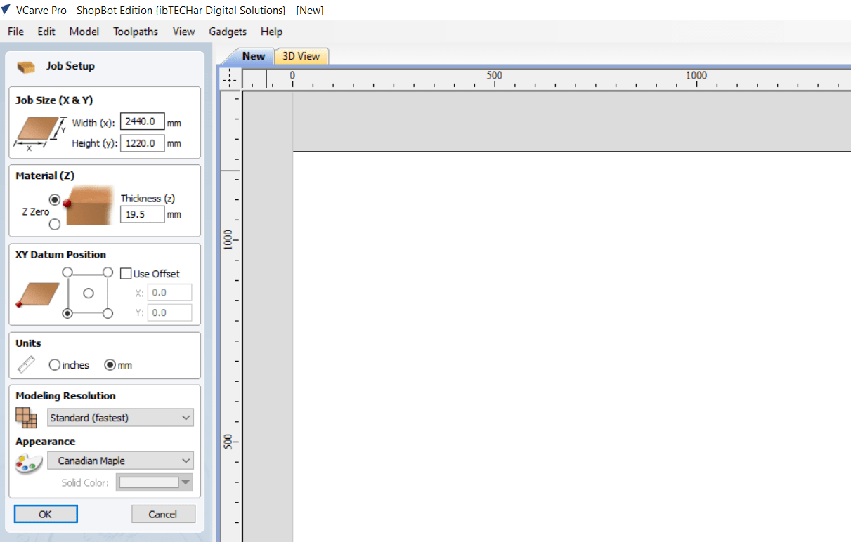
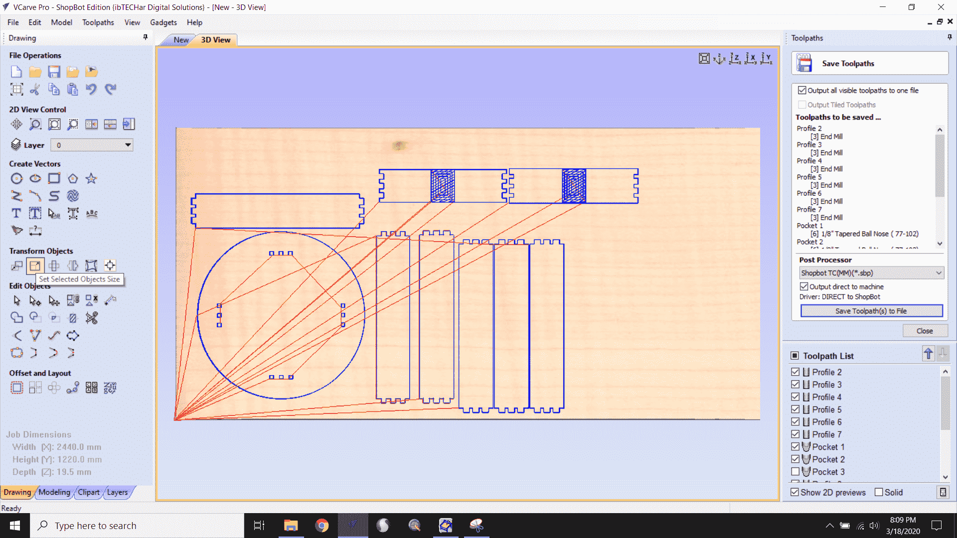
First to do on Vcarve software was to open a new file from the small menu in the left side the screen. Then it will ask to set the parameters of the material used during cutting: Width, height and thickness. Then press Ok, as shown below.
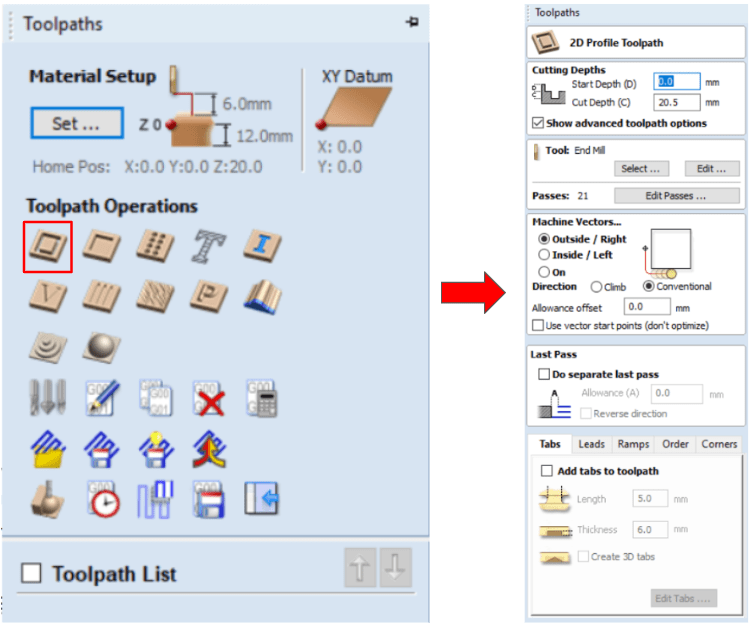
After setting up the material parameters, the .dxf files got uploaded to the machine and the 2D profile toolpath parameters were modified.
The actual material thickness was 19 mm, however the cut depth was set to 20.5 mm in the software. The reason behind that was to reduce the error and guarantee the process of cutting through the material.
Regarding the number of passes, to have a perfect cut it recommended to set 1 pass for each mm of cutting. However to reduce the time of cutting the passes was set 12 passes.
Regarding the machine Vectors, “Outside/Right” was chosen for the finger parts which will be fixed in the female parts. “On” cutting was used for the female part. This process of cutting was concluded after performing several trials to get the best cut.
Shown below the parts ready for the cutting process
.
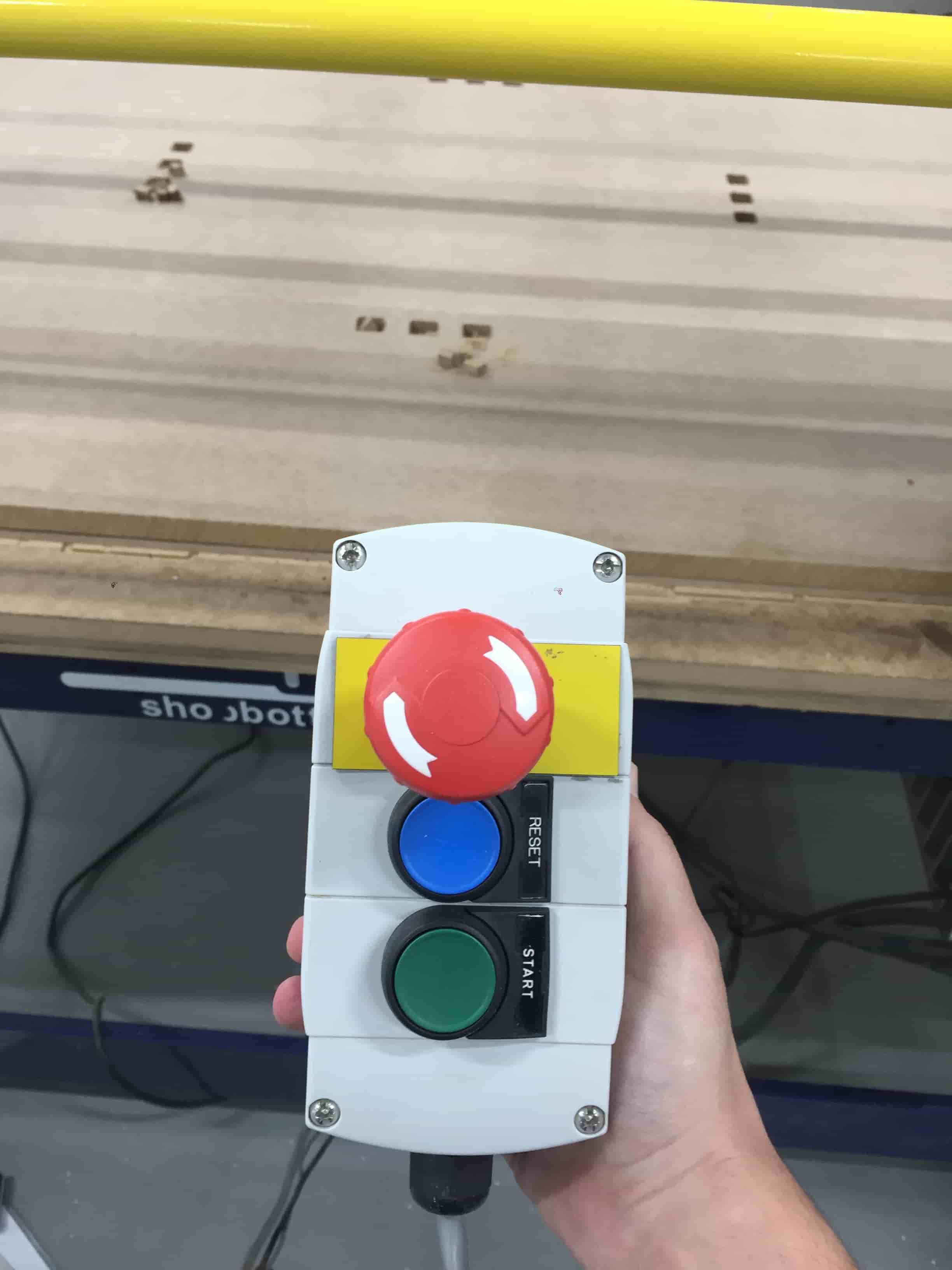
Finally the file was saved and the design was ready to be cut. To start cutting, I had to open again the ShopBotEASY panel and press on “Cut Part”. The file saves “.sbp” format was uploaded and cutting started by pressing on the green button as shown below.
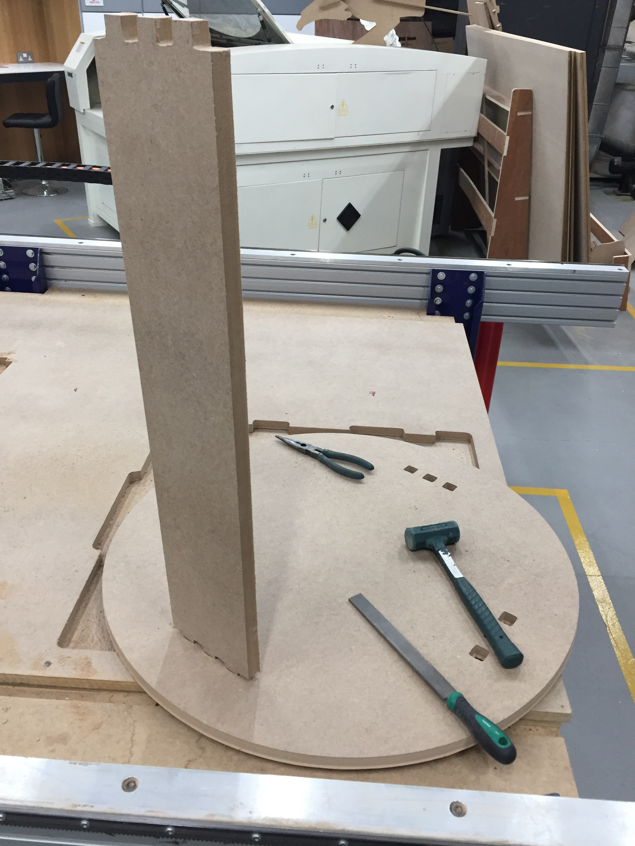
After cutting process, smoothing the material cutting surface was performed using filing tools and a soft hummer for assembling all parts together.
Challenges faces
The most challenge faced during the assignment, was to select the perfect joint thickness and recognizing the machine error. To overcome this challenge multiple trials where performed by changing the material thickness and cutting parameter. The trial and error process caused to alots of MDF wood waste, however I was able to reach to the best dimension for cutting.
Lorem ipsum dolor sit amet, consectetur adipisicing elit. Mollitia neque assumenda ipsam nihil, molestias magnam, recusandae quos quis inventore quisquam velit asperiores, vitae? Reprehenderit soluta, eos quod consequuntur itaque. Nam.
Circus Tent
Lorem ipsum dolor sit amet, consectetur adipisicing elit. Mollitia neque assumenda ipsam nihil, molestias magnam, recusandae quos quis inventore quisquam velit asperiores, vitae? Reprehenderit soluta, eos quod consequuntur itaque. Nam.
Controller
Lorem ipsum dolor sit amet, consectetur adipisicing elit. Mollitia neque assumenda ipsam nihil, molestias magnam, recusandae quos quis inventore quisquam velit asperiores, vitae? Reprehenderit soluta, eos quod consequuntur itaque. Nam.
Locked Safe
Lorem ipsum dolor sit amet, consectetur adipisicing elit. Mollitia neque assumenda ipsam nihil, molestias magnam, recusandae quos quis inventore quisquam velit asperiores, vitae? Reprehenderit soluta, eos quod consequuntur itaque. Nam.