- Individual assignment
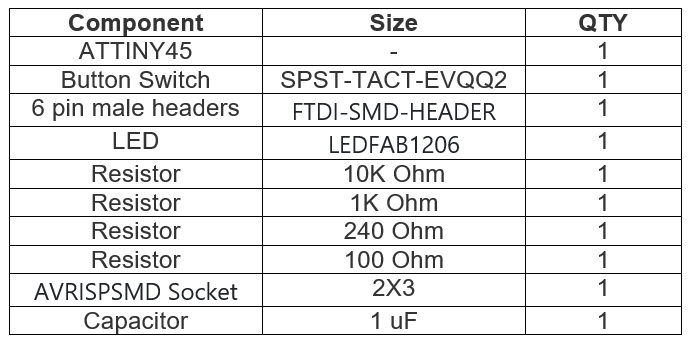
For this week assignment the shown below echo hello-world Attiny 45 board was drawn on Autodesk Eagle and printed.
ATTINY45 is high performance, low power controller from ATMEL. It is an 8 bit controller based on Advanced architecture. It is one of members of ATTINYXX series, popular because of its small size and features.
In addition to the Attiny45 board an LED and push button was added to PCB. For these components the current limiting resistor and pull-down resistor had to be added.
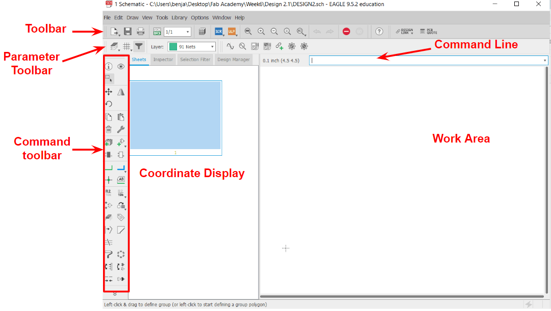
Once all components needed to design the board were specified. The Autodesk Eagle software was downloaded and used to select all components and design the board. Below shown the software interface
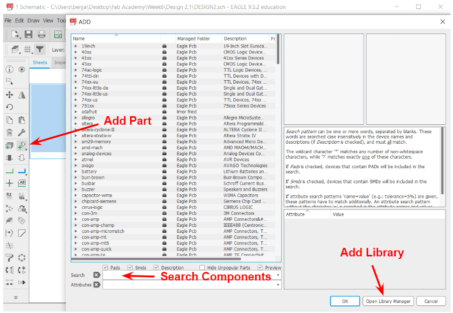
- A new project was created, and all component mentioned in the table were added. Shown below the process of adding components. Someone elements where not found so the FabAcademy library (check download link below) was downloaded and added to the software. Shown below the process of adding parts and library.
- Download link for Fab Library
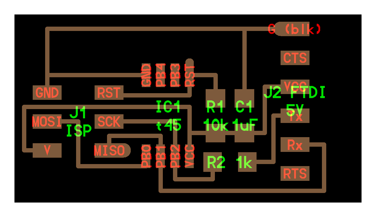
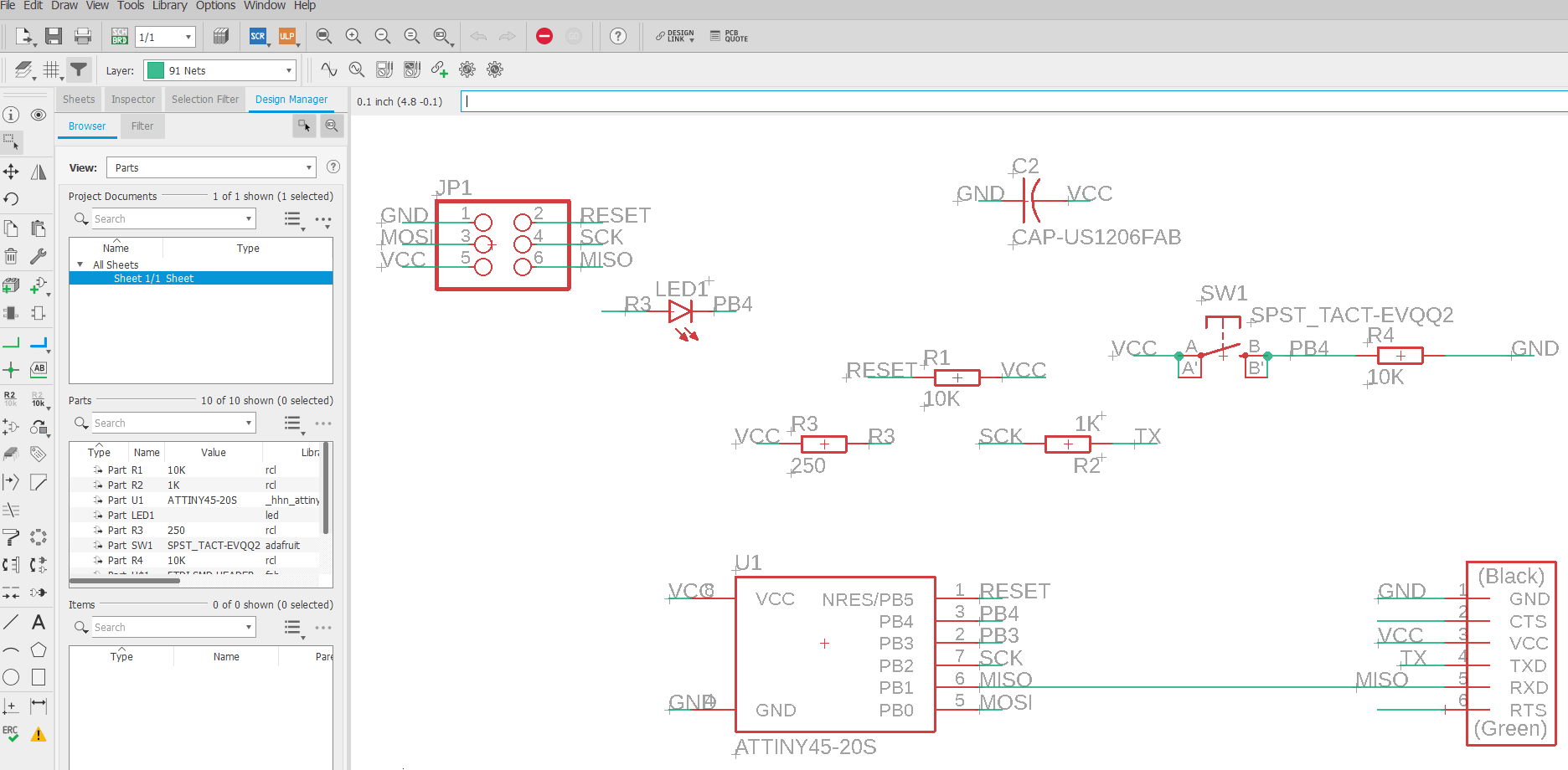
- By adding all components needed, the next step was to create the connection between the components. Below shown the components connected.
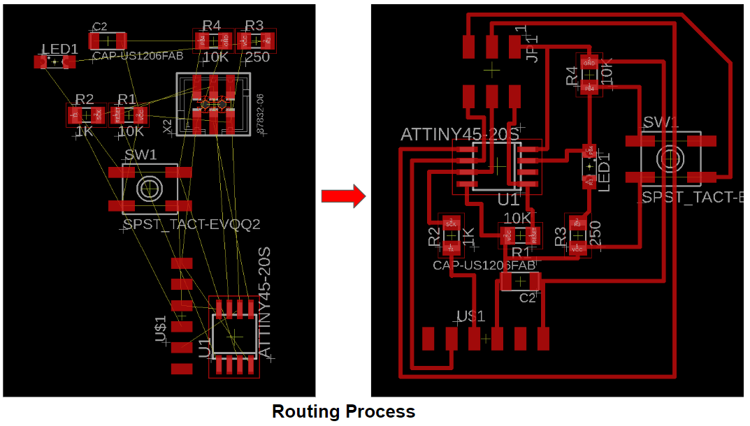
- Once connection was made, the next stage was to create board and start the routing process. Shown below the process of result of routing
Click on text below to download Eagle File:
- - Hello Board Eagle schematic folder
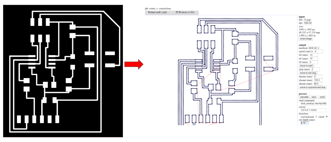
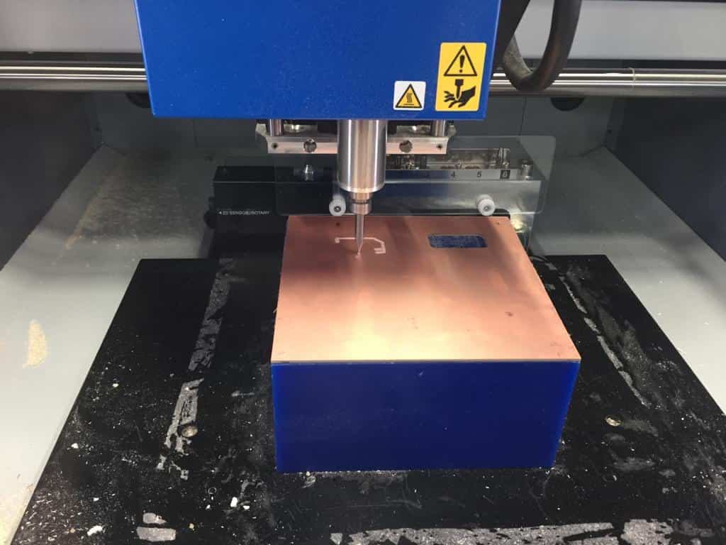
- Then the Roland milling machine was used tp perform for tracing and cutting as shown below.
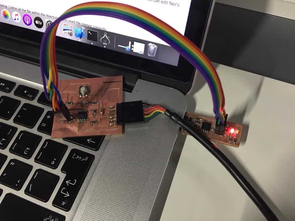
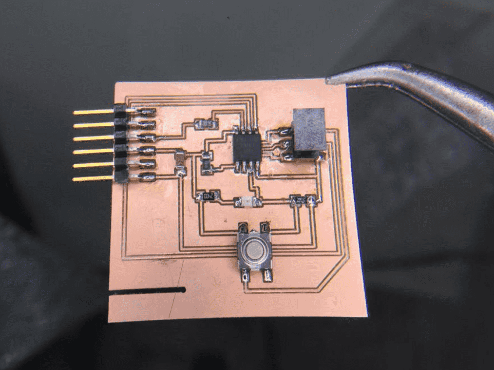
- Once the board was ready, the soldering process started. Below shown the result of soldering .
- At this stage the PCB was ready to be programmed. So it was connected to the computer and the started programming it using Arduino IDE