Assignment 4 objective


The fourth week assignment consists of two phases:

  1. Group Assignment:
    Characterize the design rules for your PCB production process: document feeds, speeds, plunge rate, depth of cut (traces and outline) and tooling. And document the work (in a group or individually).

  2. Individual Assignments:
    Make an in-circuit programmer by milling and stuffing the PCB, test it, then optionally try other PCB fabrication process.

Learning outcomes:

  • Described the process of milling, stuffing, de-bugging and programming.
  • Demonstrate correct workflows and identify areas for improvement if required.

    1. Group assignment

    The purpose of the group assignment is to characterize the design rules for the PCB production process. However, before explaining the PCB process I would like to share with you the machine and software used for producing the PCB.

        The Software :

        We have been introduced to the Fab Modules which is a browser-based computer aid manufacturing system, allows to generate toolpaths for CNC-milling and lasercutters as well as waterjets. This web-based system will be used to setup the parameter of the PCB that will be traced and cut.

    The Machine Description:

    We have been introduced to the MODELA MDX-50 which is a fully automated, high-precision 3D milling machine ideal for fabricating desig n and working models. The MDX-50 has an Automatic Tool Changer and CAM software.
    The MDX-50 benchtop CNC mill combines precise, automated milling and unmatched ease-of-use.


    Procedure of characterizing the design rule of PCB production

    To characterize the design rule of PCB production we had to test the precision of the machine used. To do that our fabacademy instructor provided us with a design file to be traced in the Roland and then test the accuracy of traces.

      1- First step, we have visited fabmodules website and uploaded the design as (image.png) as shown below


      2- Then the type of output format and process of cutting was selected, in our case we selected Roland mill (.rml) as format and PCB trace (1/64).


      3- Next step was to select the output type and change the parameters of the machine as shown below

      • Machine: MDX-40
      • Speed (mm/s): 4
      • Cut depth (mm): 0.1
      • Tool dimeter (mm): 0.09


      4 - Finally, click on calculate and Save.


      At this stage the trace file was ready, and we had to prepare the outline file to cut the PCB boarders as shown below.


      Next step was to select the output type and change the parameters of the machine as shown below

      • Process: PCB outline (1/32)
      • Speed (mm/s): 2
      • Cut depth (mm): 1.8
      • Tool dimeter (mm): 0.4
      Finally click on calculate and save the file as shown below


      Once both files were ready, we started the using the machine to trace and cut the PCB.

      First step on the machine operation was to clean the surface of cutting, using the brush. The purpose of cleaning is to remove the debris and make sure to have an equal horizontal surface over the board.


      Next step is to calibrate the machine. We had to use the Z-probe snap it over the special socket as shown.


      Also, we had to make sure that the detection pin is loaded to tool slot number 6. We used the hand wheel to select the tool where the bit is attached to the tool holder (tool 6) which is the detection pin is selected. The spindle will move to get the selected tool then it will show on the screen that the selected tool is tool 6.


      At this stage the Z axis is ready to be calibrated, We used the hand wheel to move, the x and y to have the spindle directly facing the z-probe metallic piece. After that, clicked on Z0 SENSE from the panel. There will be a message displayed on the screen, to confirm Z0 SENSE click ENTER.


      The final step in setting up the machine was to use the automatic tool changer to pick the milling tool 1 (V-tool) and then to pick tracing tool.


      Then we had to plug in the USB in the laptop and upload the file in the machine software. As shown below.


      We opened VPanel and selected “Cut” icon. This allowed us to upload the RML file for the PCB. Then it automatically added to the list of cut files. Finally, make the file was ready to be cut by selecting the file and clicking “Output”. Once we click on cut the machine will start operating and the result of tracing is shown below.


    To sum up, the purpose of this section was to test the machine accuracy by varying the machine tools and parameters. As a result, we have concluded that the Roland machine is able to cut boards of 0.001 mm with high accuracy. There was no variation between the designed part and the actual printed part.

    1. Individual assignment

    For the individual Assignment we had to make an in-circuit programmer by milling and stuffing the PCB. In this section I will not cover in details the machine operation process as it was covered in the group assignment section. However I will focus on soldering part and testing of the PCB.

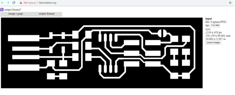
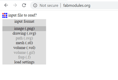
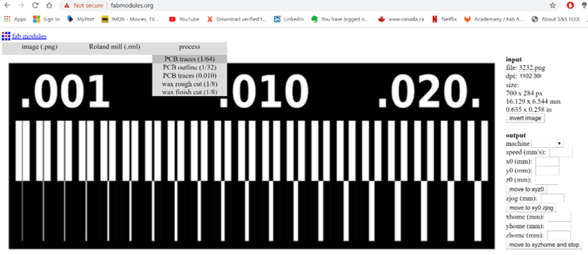
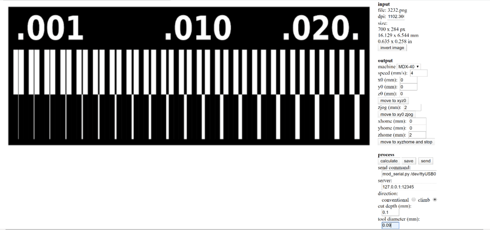
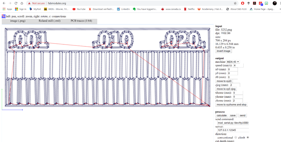
    First step we have uploaded the file in the FabModules website and set the cutting parameters as shown below.


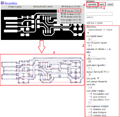
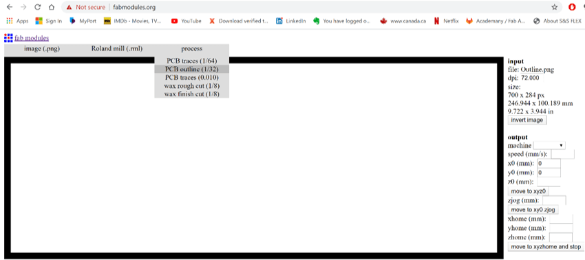
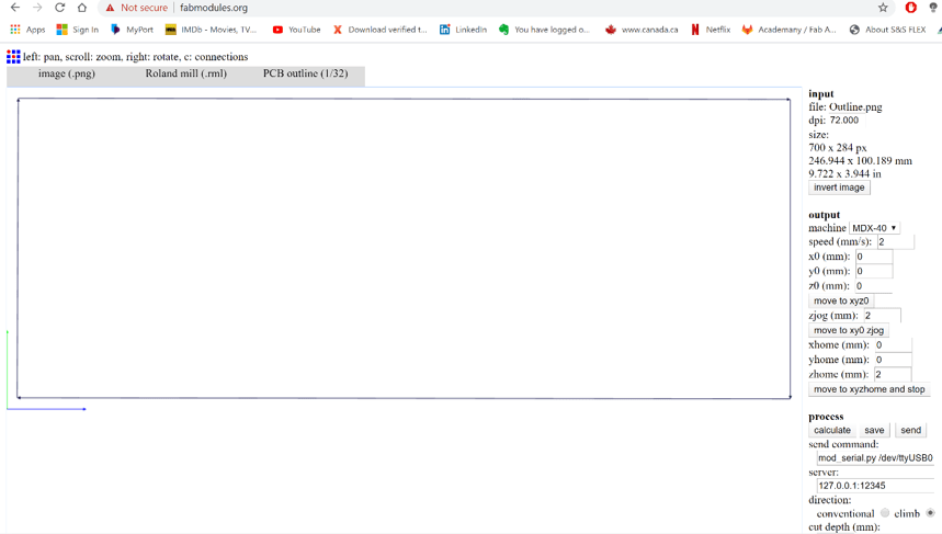
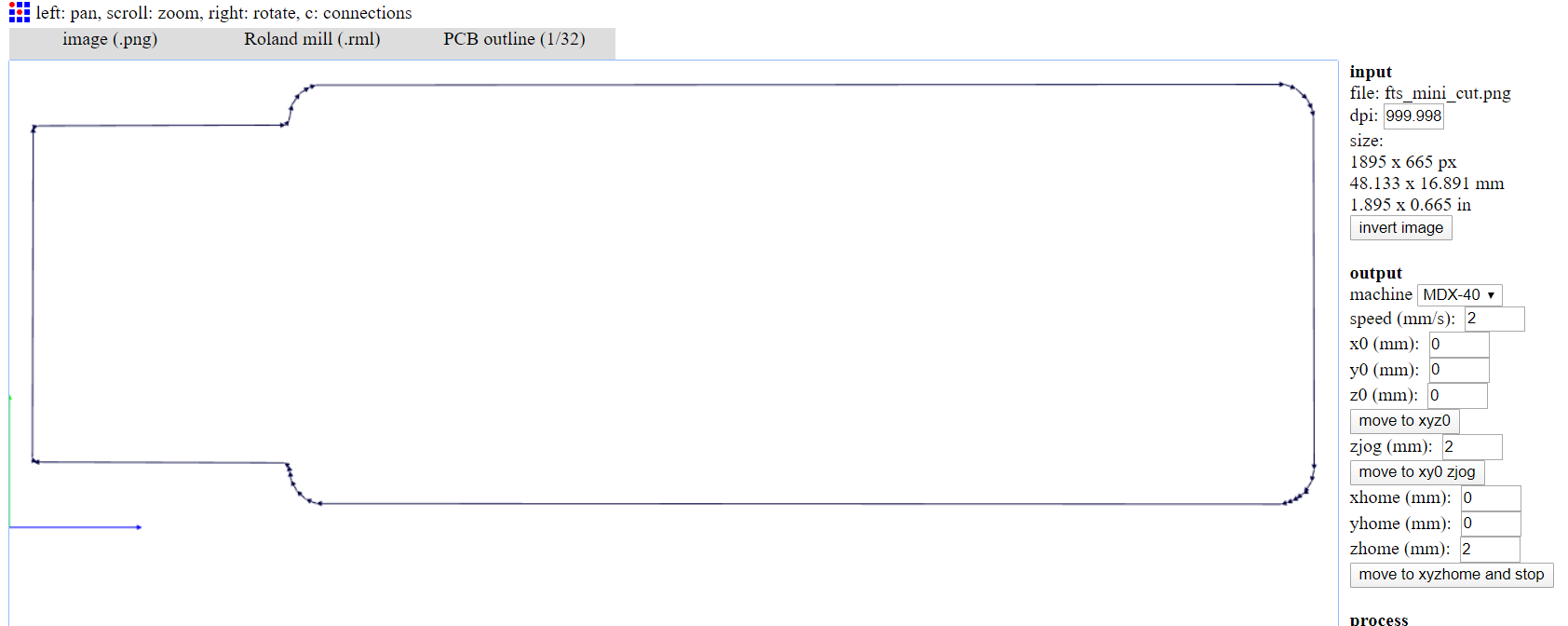
    Same process was repeated for the outline file, by changing the parameter to 1.8 mm depth of cutting and PCB outline (1/32).


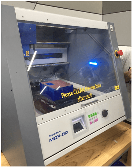
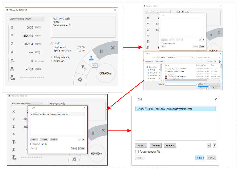
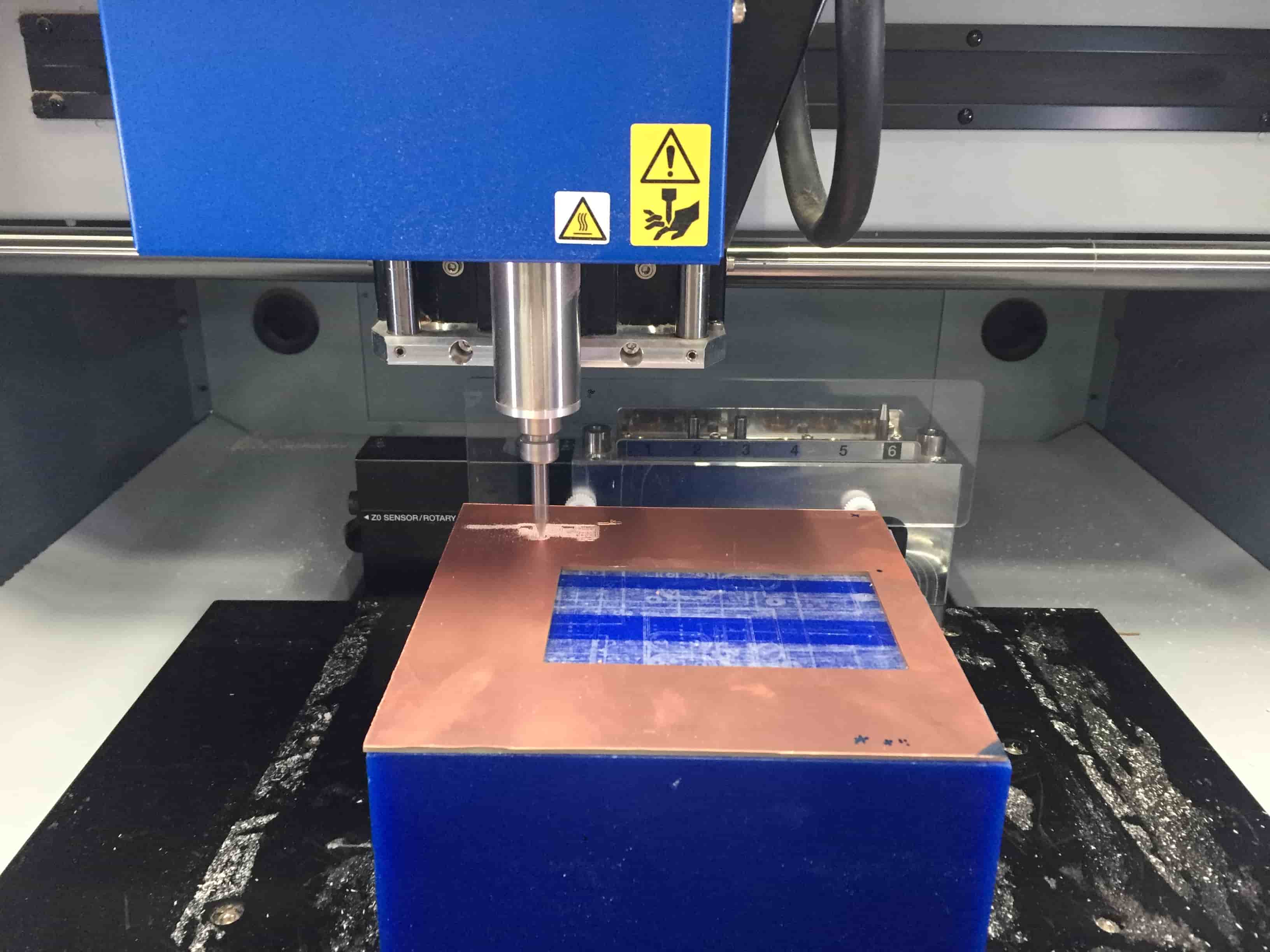
    Then files were uploaded to the machine to perform the tracing and cutting as shown below the machine operating.


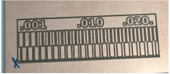
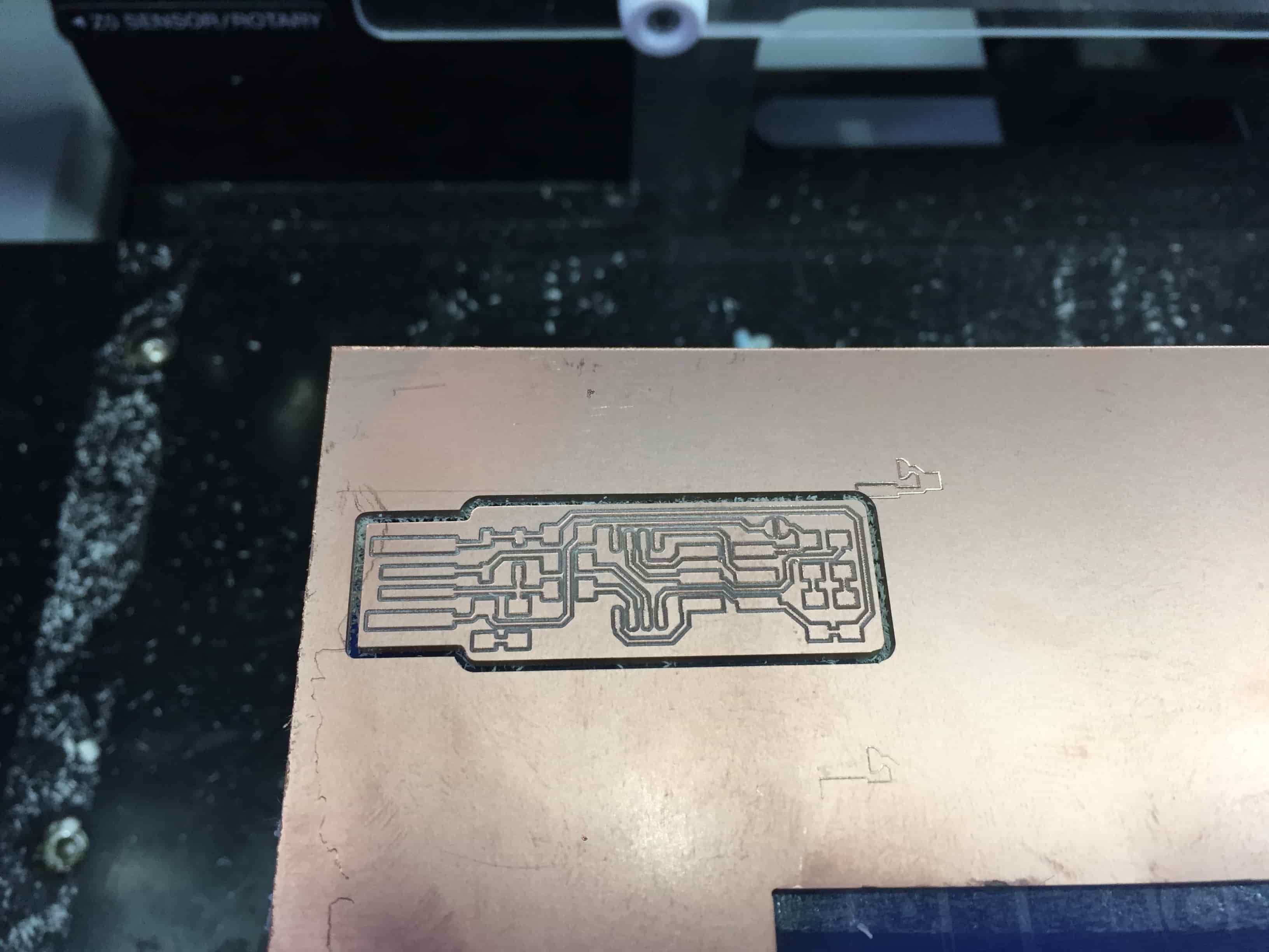
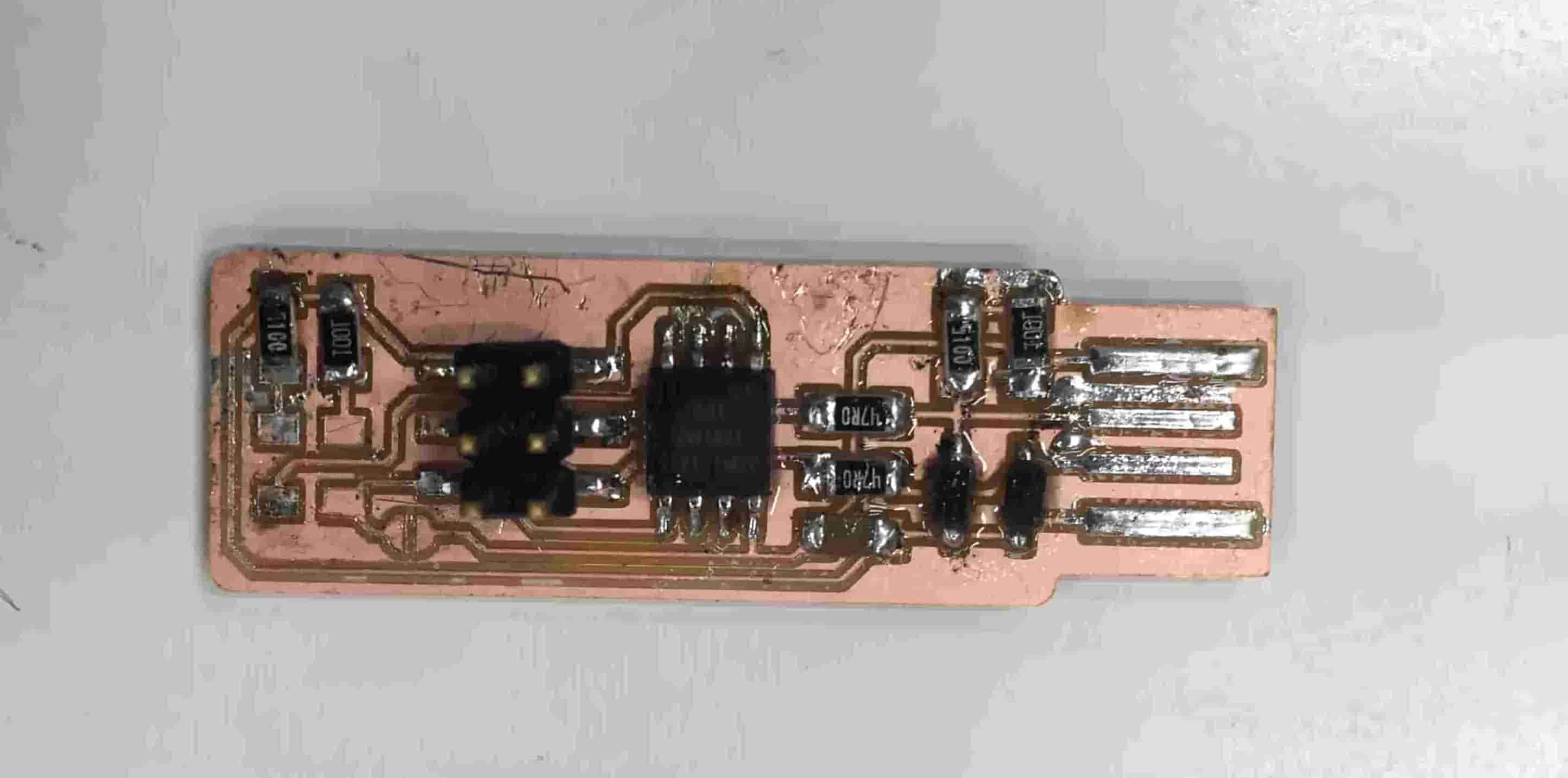
    Result of CNC milling shown below. Now the PCB is ready for the soldering part.


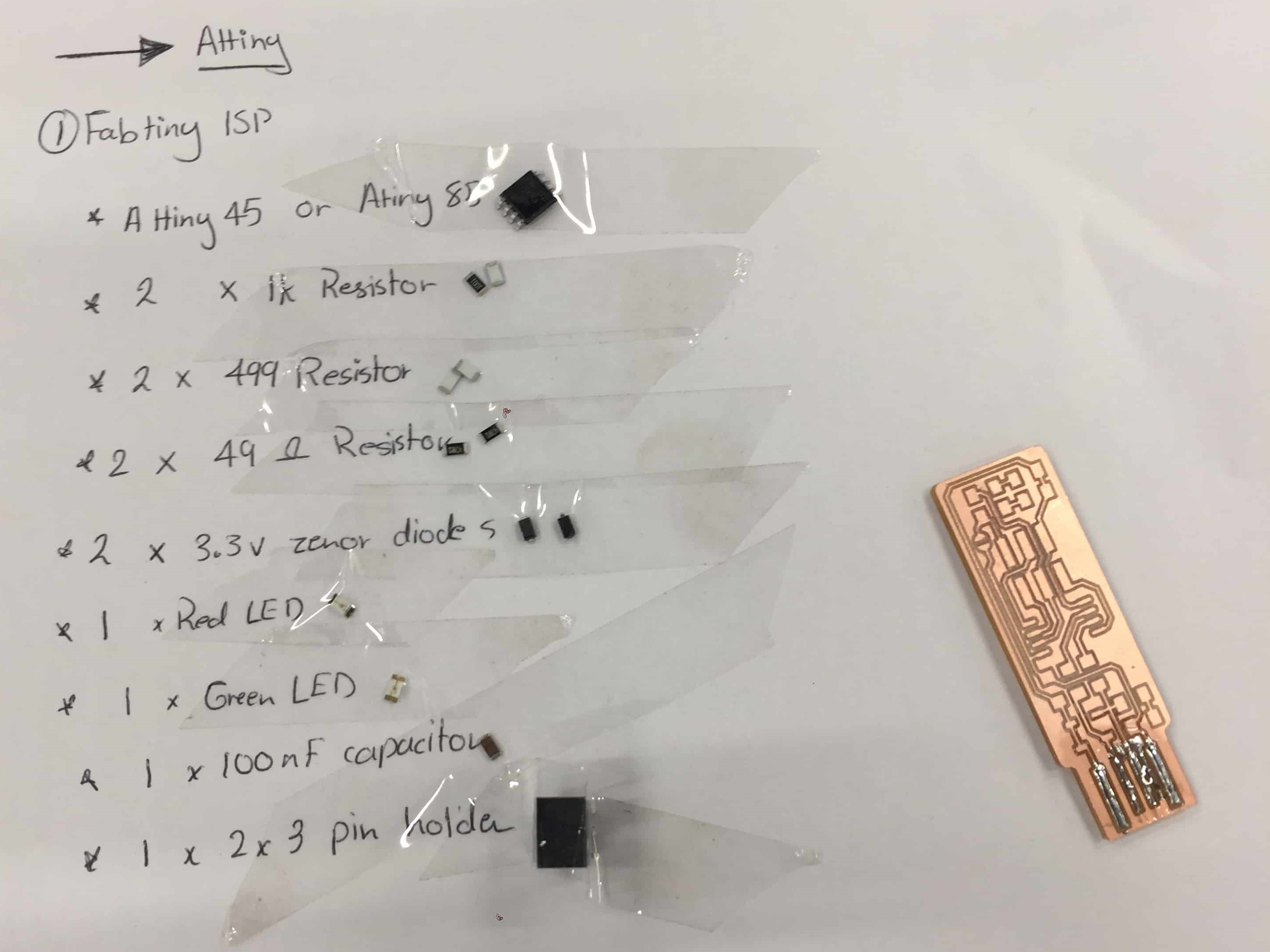
    At this stage I had to prepare the list of components needed to be soldered on the PCB. The Fabacademy instructor supported us to select the exact components for the PCB as it was challenging with the small SMT (surface mount technology) pieces. Below is the list if components mounted on the PCB.


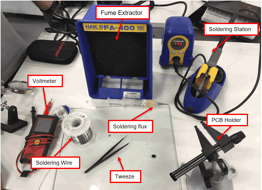
    As the components were ready, I made the set up for the soldering station. As shown below all tools used during the soldering process.


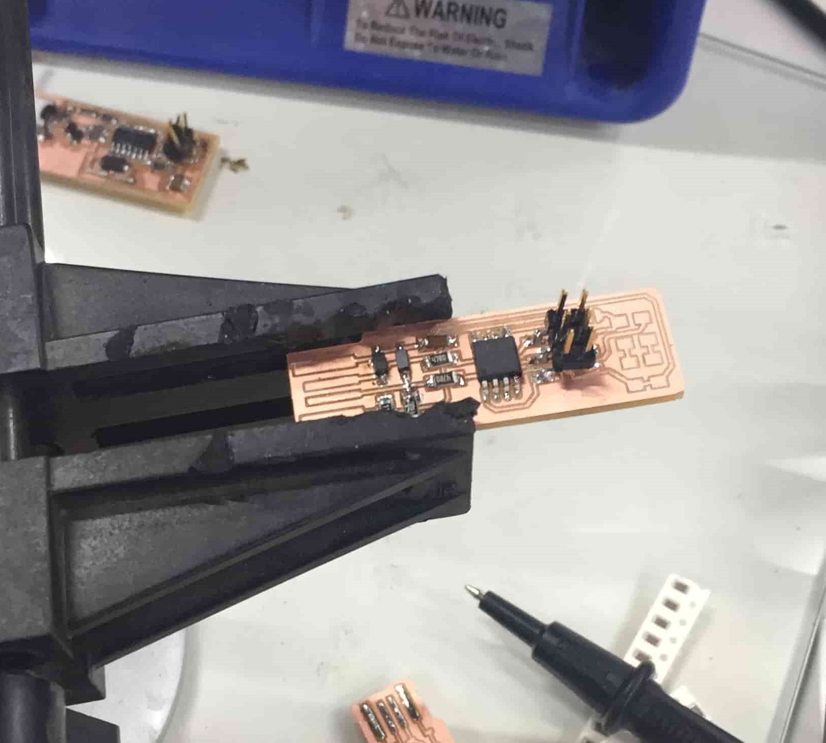
    The soldering process started by making different trials for random components. It was challenging to solder the SMT component, however after few tests I managed to get succeed. Shown below the progress of soldering.


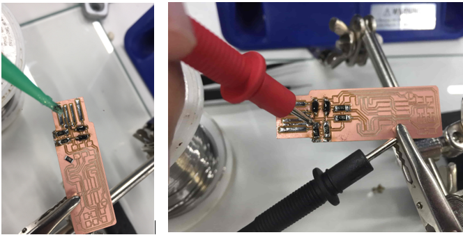
    One of the important steps to follow during the soldering process is to conduct the continuity test to check if current flows or not. This was done by using the multimeter, if a short circuit occurred the device will buzz, and this means the issue should be solved by dissoldering and repeating the process carefully.

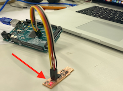
    Finally, I was able to finish soldering the PCB and test it the computer. By having the LED turned on shows that the soldering was a success.


    Challenges faced

    For my case it was my first-time soldering PCB with SMTs. It was very challenging for me to hold the tiny SMT in the board and solder it. Multiple times I was having a short circuit and had to fix it. In total I had t repeat the process 3 times and the third was success, but it was a fun experience and taught me how to be very passion and very sophisticated. Below shown the unsuccessful trial 1.


    Additionally, I have used the soldering flux as it helped on removing any oxidized metal from the surfaces to be soldered, seals out air thus preventing further oxidation, and improves wetting of the liquid solder. Shown below both continuity test and flux usage.


    Programming FabISP with Arduino


    To program the FabISP I followed instructions provided in Fab Tutorials. It was recommended to use Mac for to program the ISP for easier process, however it can be done on any operating system. So I used my colleague Mac laptop through out the process.
      1- First step was to download the FabISP firmware. XCode and Crosspack AVR.Once the required files are downloaded, I unzipped the firmware folder.
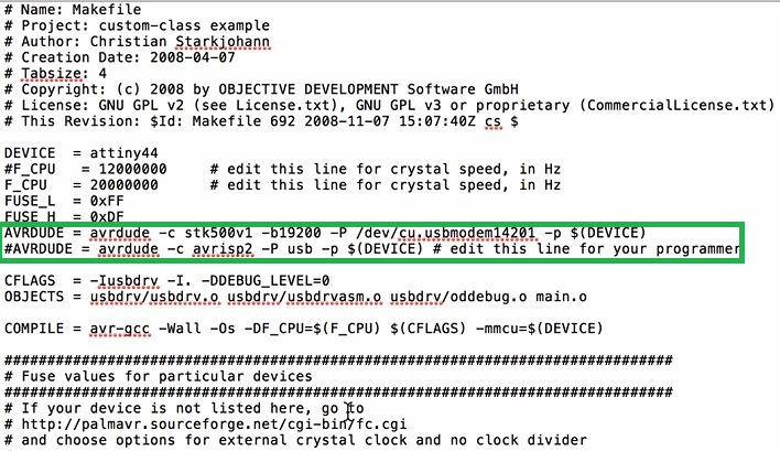
      2- Open the make file contained within the firmware folder and it was edited as per instructed

      AVRDUDE = avrdude -c stk500v1 -b19200 -P /dev/cu.usbmodem14201 -p $(DEVICE)
      #AVRDUDE = avrdude -c avrisp2 -P usb -p $(DEVICE) # edit this line for your programmer


      3- To find the port, simply open the Arduino IDE and checked through there since I was using and Arduino Uno as a programmer. The port will shown us as: /dev/cu.usbmodem14101 (Arduino/Genuino Uno).
      4 - Access the firmware file cd desktop/fabISP_0.8.2_firmware
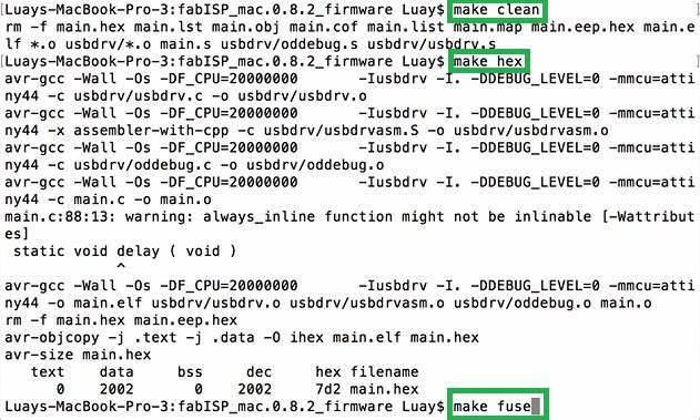
      - Make sure any unneeded previous compiled files are deleted, use the following commend: make clean.
      - Compile the programming code by executing: make hex
      - Create the fuses to use the external clock by compiling: make fuse or alternatively/ proceed to create the fuses and flash the program to your board in one command: make program.

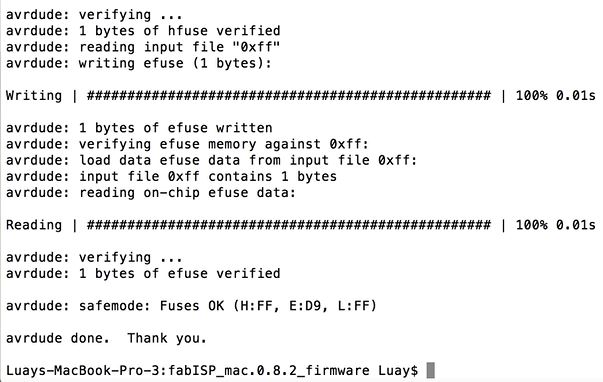
      This is all the code needed to successfully program the Attiny44 as an ISP.


      the board functioned as planned and I was able to program it. The terminal window yielded the following output.


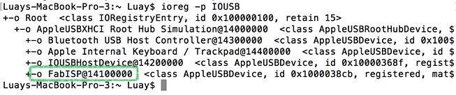
      To check that the FabISP is functioning correctly, through terminal ran "ioreg -p IOUSB" and shown below the result of connection succefully