Assignment 3 objective


The third week assignment consists of two phases:

  1. Group Assignment: Characterize your lasercutter's focus, power, speed, rate, kerf, and joint clearance .

  2. Individual Assignments:

      a. Parametric Press Fit Contrcution Kit:Design, lasercut, and document a parametric press-fit construction kit, which can be assembled in multiple ways. Account for the laser cutter kerf.
      b. Vinyl Cutting:Cut something on the vinyl cutter.

Learning outcomes:

  • Demonstrate and describe parametric 2D modelling processes.
  • Identify and explain processes involved in using the laser cutter.
  • Develop, evaluate and construct the parametric construction kit.
  • Identify and explain processes involved in using the vinyl cutter.

    1. Group assignment

    The purpose of this assignment is to test QBIC Fablab Laser cutter’s focus, power, speed, kerf and join clearance. below shown the machine specifications used in the lab.

        Machine Description :

        The G.WEIKE LC1390S is a high precision laser cutting machine that focuses a high energy laser beam onto a material resulting in a high quality and dimensionally accurate cut. The laser cutter can be used to cut, etch, engrave, drill and to cut a variety of materials. Generally laser cutting machines contain a carbon dioxide (CO2) laser that produces invisible laser radiation at a wavelength of 10600nm in the infrared spectrum.
        The LC1390S has a maximum cutting area of 1300 x 900 mm, uses laser power of 800 W and operates at 110-220V - 50 and 60 Hz AC supplies. The machine has a very thin focal point of 0.2mm width, this makes the machine highly precise and convenient for all kinds of precision instrument industries. Unlike other milling technologies, laser cutting is superior due to the cleanliness of material cutting which leads to material saving from being lost while milling. Furthermore, it has a very fast cutting speed of 0-24000 mm/min which greatly minimizes the time needed for cutting. http://www.gwklaser.com/pdf/LC1390.pdf

        Model:

        1. Laser Type: CO2
        2. Laser Power: 800 W.
        3. Working area: 1200 x 900 mm

    Procedure to Operate the Machine

    To learn how to use the machine, our fab academy instructor gave us a brief on how to safely operate the machine by taking us through an example which is shown below.

    - The first step was to save the 2D file made previously as a .DXF file. Dxf (Drawing Exchange Format) is the type of format recognised by the laser cutter software. As shown is the interface of Lasercut 5.3 software, this software can be used only if the dongle USB key is attached to the computer.


    - The instructor imported the .DXF and modified the cutting setting from the software. There are 3 parameters that can be varied which are Speed, Power and the order of cutting. As shown below.

    - Next step was to export the file in a USB to be cut in the laser cutter.


    The instructor gave as instruction and precautions to operate the machine:

      a. Allocate the fire extinguisher and know how to use it, in case of fire.
      b. Turn On the machine and let the laser head to return to its datum


      c. Check the water level on the chiller system
      d. Turn On the ventilation system and the air compressor.


      e. Place the Material to be cut on the cutting workspace.


      f. Press on Test, this will show the area that will be used for cutting.


      g. Press Start and make sure that the door should be closed before starting .


    Testing the Kerf of the laser cutter

    The laser itself has a thickness, called a kerf. Because the laser burns or vaporizes material, the kerf is the thickness of the portion of the material that is lost when the laser cuts through. Each laser cutter has its own kerf value depending on Speed of cutting, the material, its thickness and machine power.

    In this section we will determine the kerf value by designing a parametric joints and test the clearance between the joints. We have tested two different material, Cardboard 4.2 mm and MDF 6.2 mm

    1. Kerf test on Cardboard 4.2 mm (Power 100, Speed 20)
    First step was to design a parametric joint on solidwork. We have set the joints thickness ranging from 4.2 mm to 3.0 with an increment of 0.2 mm, as shown below.


    Once design is ready, it should be saved as .dxf and imported to lasercut 5.3 software as mentioned in the Machine operation procedure section. For our machine, to be able to cut through cardboard 4.2 mm the power should be 100 with a speed of 20. Then operate the machine and obtain the result


    Final step is to connect the joints and compare them with different thicknesses.


    After performing the kerf test experiment on cardboard 4.2mm we conclude that the cardboard 4.2 mm would fit exactly with a joint cut of a thickness of 3.4 mm.
    That being said the laser cutter has a kerf value of 0.8 mm.

    Click on text to download 2D file:

      - Kerf Test design file download link


    II. Individual assignment

    1. Parametric press-fit construction kit design


    The 2D model was designed using Autodesk Fusion 360 where parametric designing took place by varying the joints thickness, dimension and number of patterns. The design made was an inspiration from the FabLat Pavilion project which was an initiative of the Latin American network of digital manufacturing laboratories.
    I have decided to use Fusion 360 since I have never used it before and it was a good opportunity for me to learn new CAD softwares. Additionally, my colleagues have recommended me to use Fusion 360 since it had clear parametric design instructions.


      First step I have downloaded Fusion 360 and got familiar with the software. Below shown the software interface


      The interface consists of the following:

        1 - Data Panel: Access teams, projects, and designs, manage design data, and collaborate with others from the Data Panel.
        2 - Application Bar: contains different tools.
        3 - Profile, Preference, Notification, and help: Notification Center, Extensions, Job Status, Profile.
        4 - Toolbar: Use the Toolbar to select the workspace you want to work in. The tools on the Toolbar differ in each workspace. The Toolbar is divided into tabs that organize the tools into logical groupings.
        5 - Browser: The Browser lists objects in your design (planes, sketches, parts, assemblies, etc.) and lets you control visibility of objects.
        6 - ViewCube: Use the ViewCube to orbit your design or view it from different positions.
        7 - Canvas and Marking Menu.

  • Start of Design.

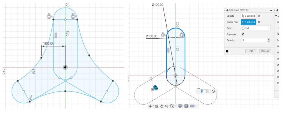
  • As mentioned previously the design was inspired by the Pavillion press fit design. To reach the final design I have made different sketches. I have also used the circular pattern feature as shown below.

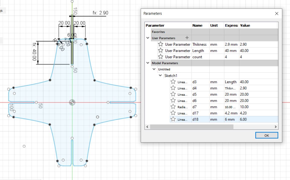
    After multiple iterations, I have reached the final design. I started with 3 patterns and then varied by changing the values on the parametric options. Below shown the design with joints thickness of 2.9 mm.


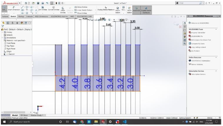
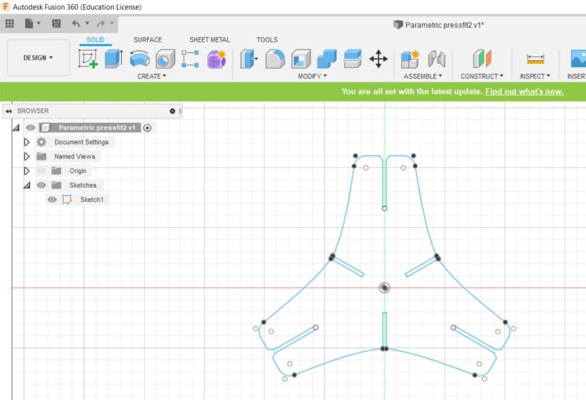
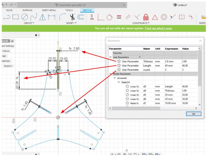
    Once the 2D design was made, the parametric feature was used to control the width, thickness of the joints and the number of circular and rectangular patterns of the design.


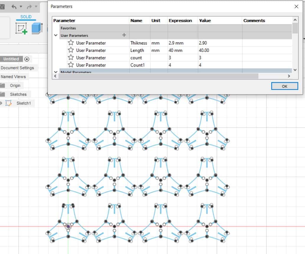
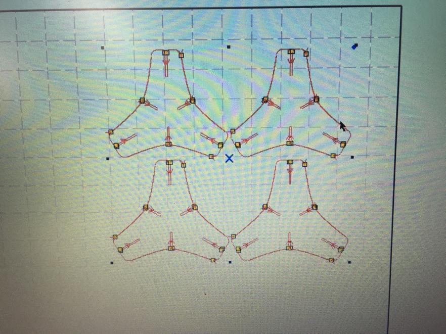
    Picture below shows the rectangular 4X4 pattern with 3 circular patterns.


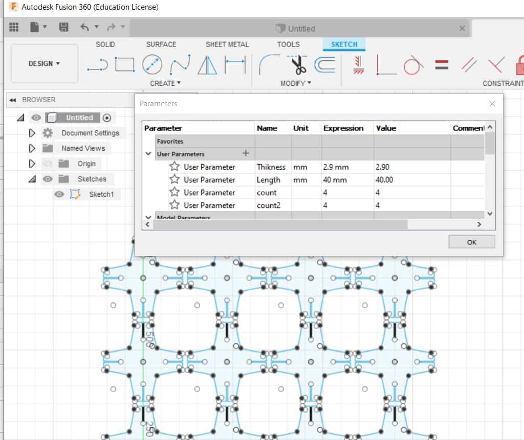
    Picture below shows the rectangular 4X4 pattern with 4 circular patterns.


  • Start of Fabrication

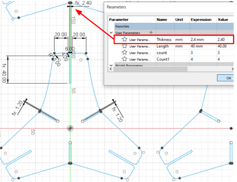
  • I have decided to test the Plywood 3.2 mm in this assignment to be able to try different materials. Based on the conclusion obtained from the group assignment, the kirf value of MDF wood was taken in consideration to be able to get a tight joint thickness. Assuming the kirf value (MDF) is 0.8 mm, I have set the thickness to be 2.4 mm as shown below.


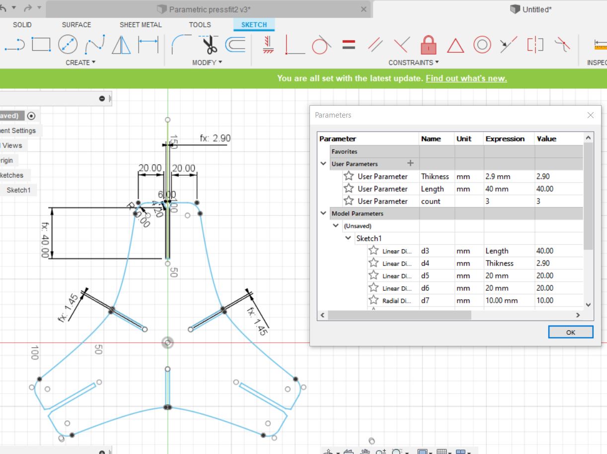
    After performing the first trial, I found out that the kirf value should be varied and this because I was using plywood instead of MDF, which will result in a different kirf value. That being said, the thickness was set to 2.9 mm as shown below.


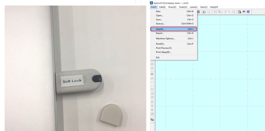
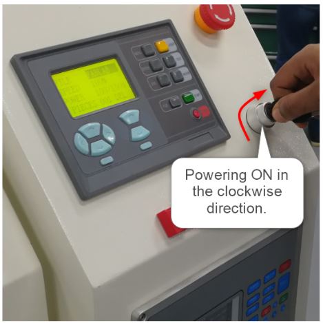
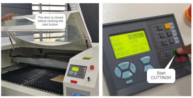
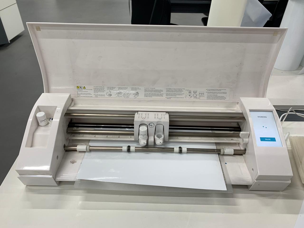
    Once the design was ready, the file was saved as DXF and imported to Lasercut software (detailed procedure of how to use the laser cutter were presented previously).


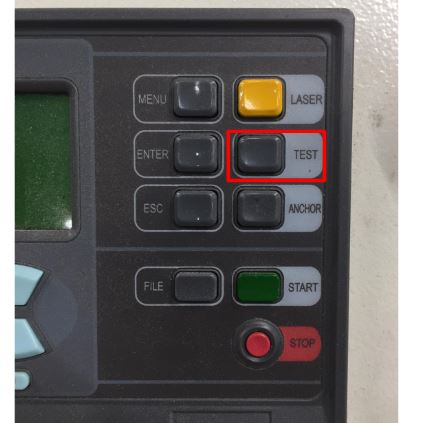
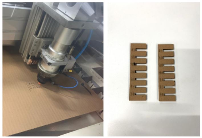
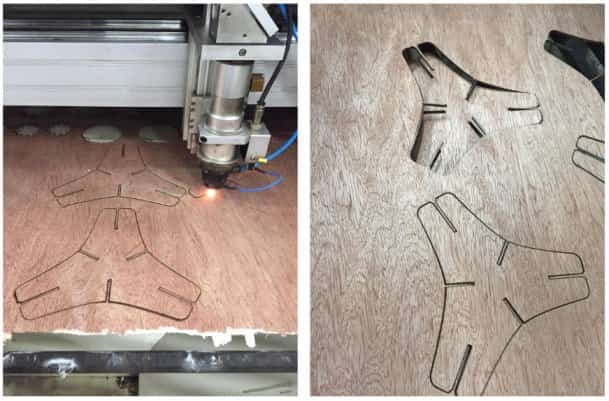
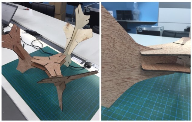
    The power of the laser machine was set to 100% with a speed of 20 % and then the machine was operated. Below shown the laser cutting for the construction kit of 3 patterns designed.


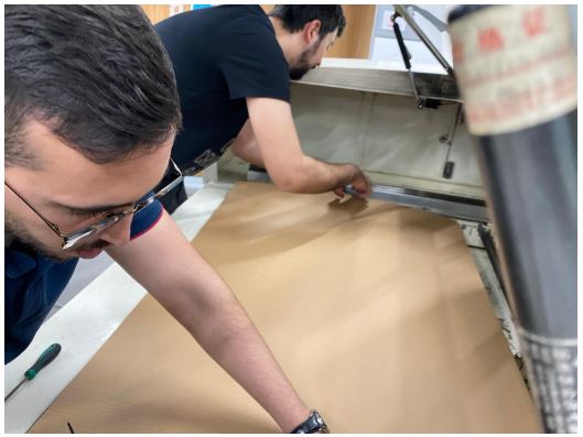
    I have faced some difficulties during the laser cutting process as the plywood sheet was bent, so the distance between the laser head and plywood sheet was not symmetric all over the cutting area. To solve this problem, I had to change the z-axis laser head distance depending on the position of cutting.

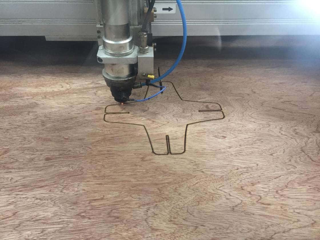
    The next step was to cut the design with 4 joints as shown below.


    Once the design was ready, the file was saved as DXF and imported to Lasercut software. During the cutting I have faced a second issue which caused failure of the cutting. The laser was burning the edges and not cutting it, as shown below.


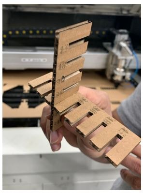
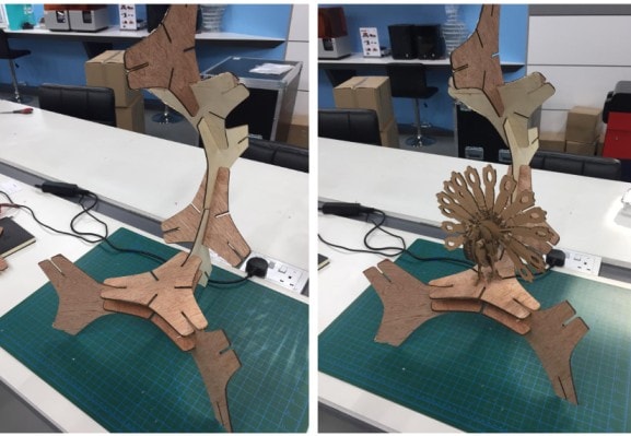
    Since there was an issue with the lase machine, I have decided to use the 3 patterns design to construct simple 1 of my kit.


    Simple 2 of different shape for the the kit


    Click on text to download 2D file:

      - Parametric design file download link
      - 4 Pattern design file download link
      - 3 Patter design file download link

    2. Vinyl Cutting


    The purpose of this assignment is to cut something using the Vinyl cutter. And this gives me the opportunity to learn how to use the machine and get familiar with the process of vinyl cutting.

        Machine Description :

        The Silhouette Cameo 3 is a fully integrated desktop cutting system. It is used to cut over 100 different materials including vinyl, paper, cardstock, fabric and other materials up to 12 inches x 12 inches (The dimensions of the cutting mat). Moreover, the Cameo 3 has a dual- carriage for multi-tool and it has a self-adjusting AutoBlade that can cut materials up to 2mm thick. Additionally, it is compatible with Print and Cut and PixScan technology. Therefore, it can be used to create printed pieces of art.


      The Silhouette Cameo 3 cutting machine comes with the Silhouette Studio software, power cable and USB cable, 12- Inch cutting mat, AutoBlade cutting blade and markers.
      The Cameo 3 has a new feature to cut materials wirelessly through built in Bluetooth or using external Bluetooth adapter.


  • Getting started with designing and cutting

  • First step is to download the Silhouette Cameo3 Studio and setup the software. the software can be used to design shapes, free drawing, text, and photos. As shown below the 12 x 12 inches cutting mat and will be used as a canvas for your design.

    Throughout my assignment I chose a photo from the internet and I used the tracing feature to perform the vinyl cutting. Shown below, the process of tracing that will be followed in my design.


    Shown below the design uploaded on the Silhouette software to be traced and vinyl cut.


    Once the design was uploaded on the software, trace feature was used to trace the outline of the design. Shown below, the result of tracing.


    Since I had the design ready to be cut, the next step was to connect the laptop to the machine and start operating the machine.


    Then the material to be cut, should be mounted over the cutting mat properly to give a good cutting result. It is important to consider the design size in the studio and to ensure that it does not cut outside the cutting area.


    The mat is then inserted under the roller bar with edges aligned with the blue marked points. Once the appropriate settings are selected for the cut, click on the “Send” to Silhouette in the top right corner of the Studio window. After cutting, the machine displays a message to indicate that the cutting is finished. Release the mat by clicking on “Unload”.


    At this point the sticker is ready, I have removed the vinyl from the mat and used scissors and spatula to cut the portion of the design. The hook was used to remove the vinyl covering the parts that need to be removed.


    Then I used a small piece of the transfer tape to the car design and started burnishing using the scrapper.


    Then I cleaned the desired surface using alcohol to make sure there was no dust or debris on the surface.


    After making sure that the transfer tape is completely stuck to the text, kindly I have peeled off tape and stick the text over any desired surface using the scraper again for burnishing.


    Finally the design was stuck on the surface and looks perfect as shown