The second week assignment object consists of two phases:
Evaluate and select 2D and 3D Software: The object of this phase is to select a CAD software, learn how to develop 2D sketches and generate a 3D model by demonstrating and describing the process through words/images/3D models. It was recommended by the Fabacademy instructors to choose a new software and learn how to use it from scratch.
Model the possible final project: The objective of this phase is develop an initial 2D and 3D design for our final project. In this phase an alternative software was used to model the final project design.
Evaluate and select 2D and 3D Software
3D Software
The local session started by discussing our experiences and familiarity with CAD softwares. Each one of us had a previous experience with a certain CAD software, however most of us never used Rhinoceros. Our colleague Katia volunteered to give us a workshop on the basics of Rhinoceros, since she is a designer and familiar with Rhinoceros. That being said we chose Rhinoceros as a 3D Software to be evaluated. In this section belwo I will be presenting the process of 3D modeling using Rhinoceros.
Rhino Interface :
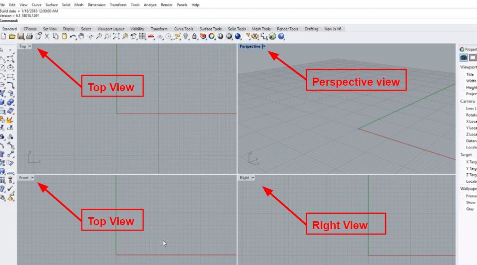
The session started by giving an overview about Rhino 6 interface. As shown below the interface has four default view ports: Perspective, Top, Front and Right. To tumble the perspective view you have click and drag with the right mouse button. You can use the control+right mouse button to zoom in and out for all view ports. To maximise the view port you can double click on the view tab.
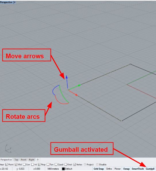
If a geometry is drawn on the plan, you can select it with the left click, as well as you select control points with the same click. As shown below the manipulator object which is called the Gumball, it can be activated from the status bar options in the bottom of the screen as shown below.
Gumball feature provide many object actions as shown below
Drag gumball arrows to Move the object.
Drag scale handles (squares) to Scale the object in one direction.
Drag arcs to Rotate the object.
Tap Alt after starting to drag to toggle copy mode.
Press and hold Shift during Scale to force 3-D scale
Press and hold Ctrl during move, scale or rotate to Extrude a planar curve or surface.
Click a control handle to enter numeric value.
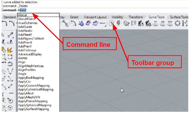
In Rhino, any feature called commends, these comments can be accessed by the toolbar groups, drop down menus can be used as well. Another method which is more often used, called the command line where you can type the command needed as shown below
2. Practical example of 2D and 3D design (cup design) :
In this section a detailed example of Rhinoceros software practice will be demonstrated by Modeling a Cup using different commendes. I will be showing steps starting from 2D to 3D design.
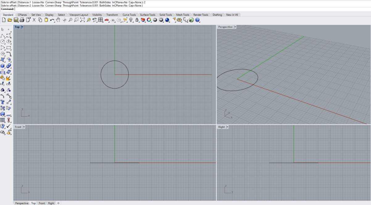
First step was to sketch the 2D model. This part will identify the dimensions of the cup (height, diameter). As shown below the sketch was drawn then feature like Trim and fillet were used to give the final 2D design.
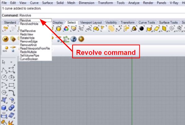
Once the sketch is made the revolve command will be used to create the 3D model. There are multiple ways to create the 3D model for example we could have used Extrude or Loft command, however for a cup, revolve command makes it simple and easy to create. Shown below the revolve command.
The steps for apply the revolve are the following.
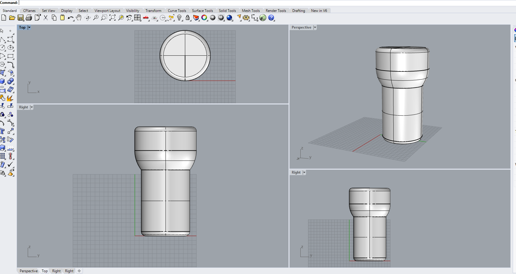
1- Select the sketch needed to be revolve2- Pick the of the revolve axis3- Pick the degree of the revolve in our case its 360 degree
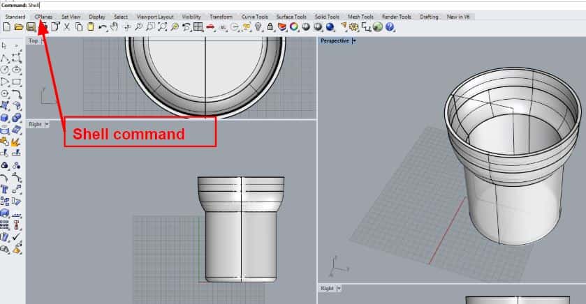
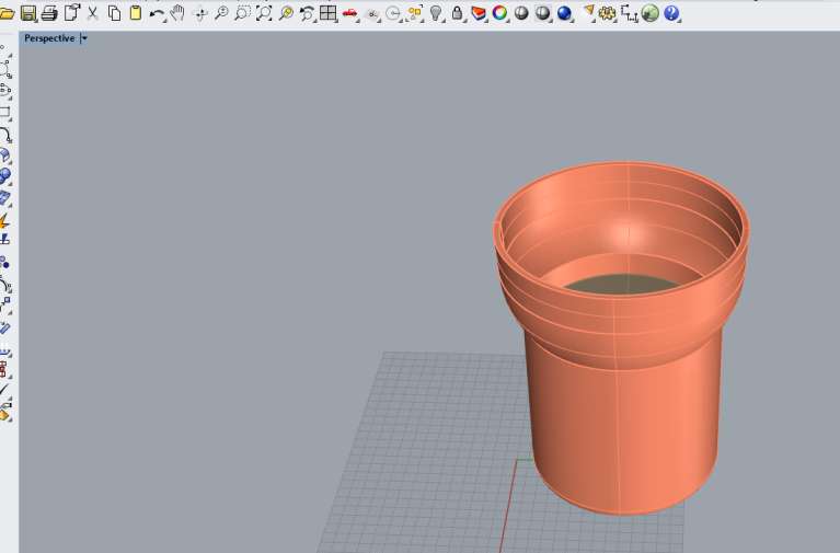
As shown in the above picture the 3D modeled cup is presented, however its a solid body. So the Shell command will be used to give the cup a top opening with a shell thickness of 2 mm. Below shown the result of the cup.
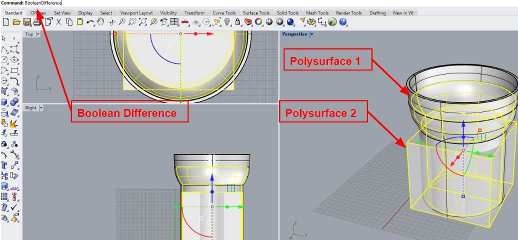
Now as we have a cup, it should contain liquide. In this step we will use the booleanDifference command which trims the shared areas of selected polysurfaces or surfaces with another set of polysurfaces or surfaces.
Steps used to follow this command are the following:
a. Select surface or polysurface to subtract from, and press enter.b. Select surface or polysurface to subtract with, and press enter.
Finally the 3D modeled cup was colored by selecting different colors as shown below.
The 2D model was designed using Autodesk Fusion 360 where parametric designing took place by varying the joints thickness, dimension and number of patterns. The design made was an inspiration from the FabLat Pavilion project which was an initiative of the Latin American network of digital manufacturing laboratories.
I have decided to use Fusion 360 since I have never used it before and it was a good opportunity for me to learn new CAD softwares. Additionally, my colleagues have recommended me to use Fusion 360 since it had clear parametric design instructions.
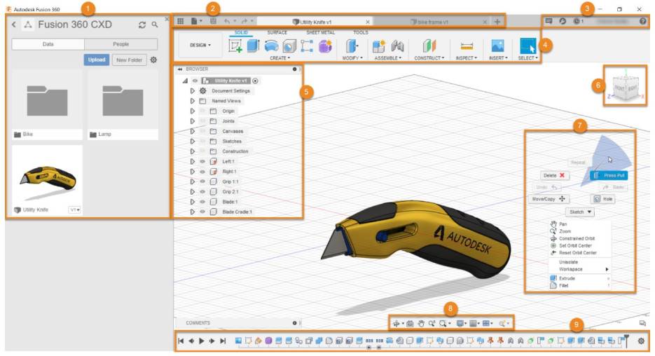
First step I have downloaded Fusion 360 and got familiar with the software. Below shown the software interface
The interface consists of the following:
1 - Data Panel: Access teams, projects, and designs, manage design data, and collaborate with others from the Data Panel.2 - Application Bar: contains different tools.3 - Profile, Preference, Notification, and help: Notification Center, Extensions, Job Status, Profile. 4 - Toolbar: Use the Toolbar to select the workspace you want to work in. The tools on the Toolbar differ in each workspace. The Toolbar is divided into tabs that organize the tools into logical groupings.5 - Browser: The Browser lists objects in your design (planes, sketches, parts, assemblies, etc.) and lets you control visibility of objects.6 - ViewCube: Use the ViewCube to orbit your design or view it from different positions.7 - Canvas and Marking Menu.
Start of Design.
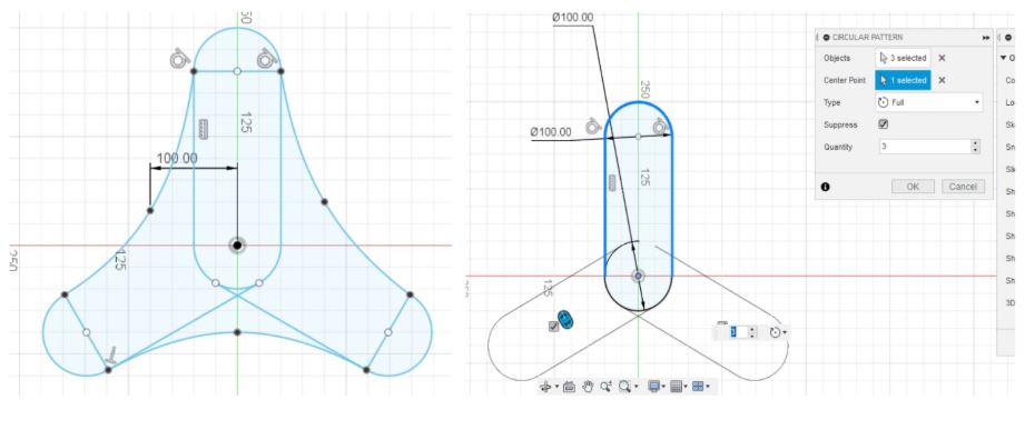
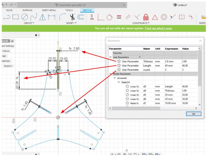
As mentioned previously the design was inspired by the Pavillion press fit design. To reach the final design I have made different sketches. I have also used the circular pattern feature as shown below.
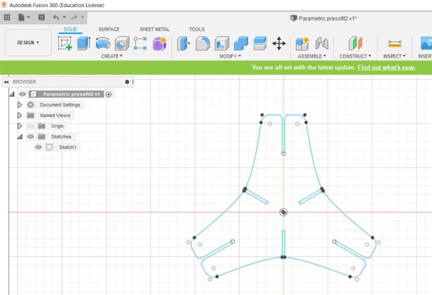
After multiple iterations, I have reached the final design. I started with 3 patterns and then varied by changing the values on the parametric options. Below shown the design with joints thickness of 2.9 mm.
Once the 2D design was made, the parametric feature was used to control the width, thickness of the joints and the number of circular and rectangular patterns of the design.
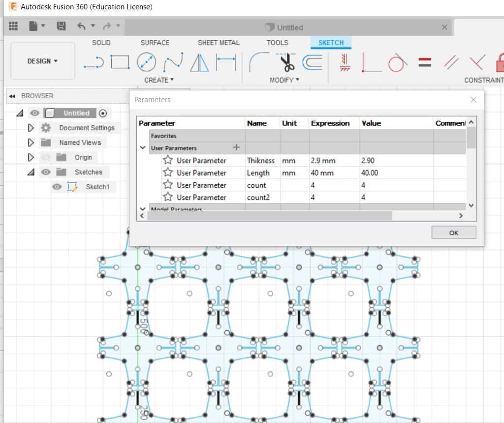
Picture below shows the rectangular 4X4 pattern with 4 circular patterns.
To conclude, the 2D design shown above will be used in Week 3 for lasercuttuing and press fit construction kit.
This section will be covering the preliminary 2D and 3D design proposed for the final project prototype. Different iterations will be performed to be able to determine the suitable design for the project needs. Below shown the procedure to create the final project model using Solidworks software.
The design consist of two major part:
- The core/container: where all the electronics and wire will be kept. - The cover: which will be covering all components and will have the display opening port.
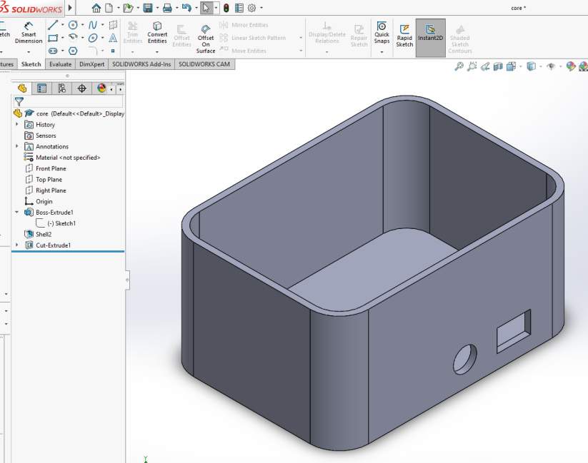
The Core/Container :
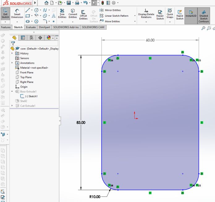
The design started by drawing the sketch of the core. The smart dimension feature was used to specify the measurement for the core. Additionally, the sketch fillet feature was used to remove the sharp edges of the design, as shown below.
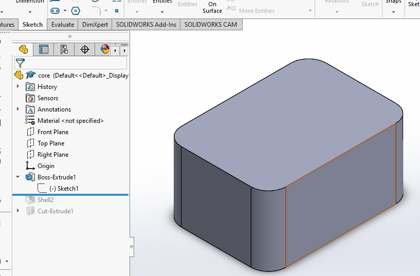
Since the 2D sketch was made, the 3D model is ready to be generated. Extrude feature was used to generate the 3D model as shown below.
The part presented above is considered as a solid body, Shell feature was used to have a top opening on the body with a thickness wall of 2mm. Additionally,the Extrude cut feature was used to identify the openings for the electronic wires to be added later on the design as shown below.
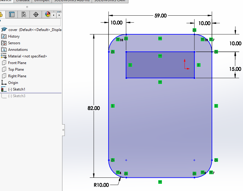
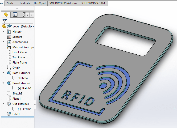
2. The Cover :
Second step is to develop the cover of the prototype. 2D sketch was made, taken in consideration of the core dimensions. The sketch consists of one opening for the LED display screen to be placed, as well as the sign of the RFID, where users will scan the membership card. Sketch is shown below.
Since the 2D sketch was made,the 3D model is ready to be generated. Extrude feature was used to generate the 3D model as shown below.
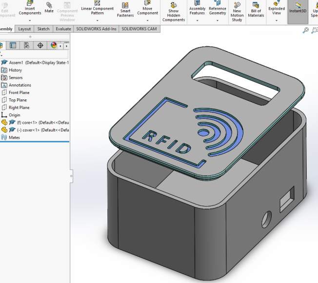
3. The Assembly :
The final step was to assemble both parts. To perform this step a new Assembly file was created and the two parts were added. Mates feature was used to restrict the part degrees of freedom. Assembled parts shown below.
Lorem ipsum dolor sit amet, consectetur adipisicing elit. Mollitia neque assumenda ipsam nihil, molestias magnam, recusandae quos quis inventore quisquam velit asperiores, vitae? Reprehenderit soluta, eos quod consequuntur itaque. Nam.
Circus Tent
Lorem ipsum dolor sit amet, consectetur adipisicing elit. Mollitia neque assumenda ipsam nihil, molestias magnam, recusandae quos quis inventore quisquam velit asperiores, vitae? Reprehenderit soluta, eos quod consequuntur itaque. Nam.
Controller
Lorem ipsum dolor sit amet, consectetur adipisicing elit. Mollitia neque assumenda ipsam nihil, molestias magnam, recusandae quos quis inventore quisquam velit asperiores, vitae? Reprehenderit soluta, eos quod consequuntur itaque. Nam.
Locked Safe
Lorem ipsum dolor sit amet, consectetur adipisicing elit. Mollitia neque assumenda ipsam nihil, molestias magnam, recusandae quos quis inventore quisquam velit asperiores, vitae? Reprehenderit soluta, eos quod consequuntur itaque. Nam.