Assignment 18 objective


This week's assignment consists of the following:

  1. Individual Assignments:
    Design and produce something with a digital fabrication process (incorporating computer-aided design and manufacturing) not covered in another assignment, documenting the requirements that your assignment meets, and including everything necessary to reproduce it.

Learning outcomes:

  • Demonstrate workflows used in the chosen process.
  • Select and apply suitable materials and processes to do your assignment.

    1. INDIVIDUAL assignment

    The assignment of this week was fun and challenging. Thankfully, at the lab we had so many machine with different technologies and this helped me to choose among many options. I was always fascinated by the 5-axis CNC machine that we have in the lab. I was very excited to try it and learn how to use it and this was the opportunity to do that. for this Assignment I will use the POCKET NC V2-10 5-AXIS machine

    The below documentation is for the purpose of education and learning new technology setup and operation.

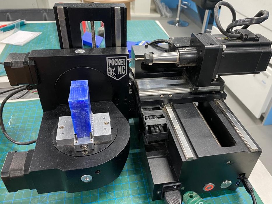
        The Machine Description:

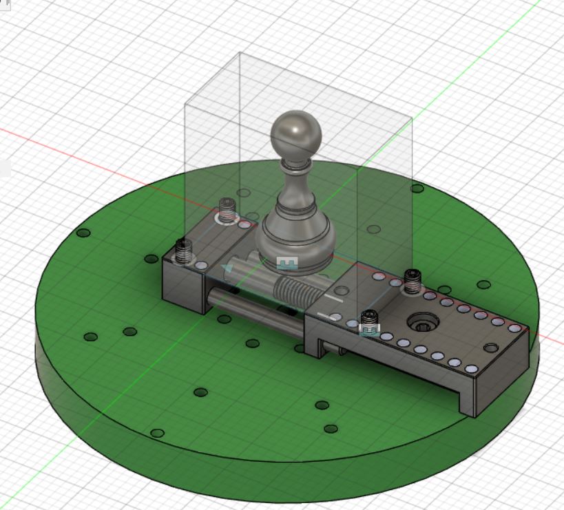
        Pocket NC V2-10 is a fully 5D capable cnc machines. Conventional milling machines typically can move in 3 linear axes at a time. An example of this would be a milling machine where the part fixed to the table can move back and forth in two directions (X and Y axes) and the cutting tool can move up and down (Z axis). The extra 2 axes of movement are rotational, which the Pocket NC have. The part can rotate about the X axis (A axis) and about the Y axis (B axis). The main advantage of this is that the machine can CNC multiple faces of the part without having to refixture it.

        Machine Specs:

        - Model: V2-10.
        - Axis Max Travel: X: 115.5 mm / Y: 128.3 mm / Z: 90.1 mm / A: -25 deg to 135 deg / B : 360 deg
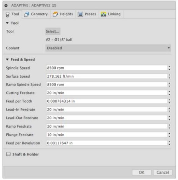
        - Spindle Speed: 1,000-50,000 RPM
        - XYZ Resolution: 0.00024 in


    I. Machine Preparation & SetUp


    The first step that was done before designing and operating the machine was preparing the POCKET NC. Below shown the steps to prepare the machine for operation:

      1- Pocket NC Network Connection
      It is very important to follow these steps to connect the machine to the internet network available in the workspace.

      Step 1: Download and Install an IP Scanner

      The IP scanner will help to search the IP address of the POCKET NC and access the machine User Interface. In my case I have used Advanced IP Scanner.

      Step 2: Turn On the Machine and Connect it to the Network
      :

      For this I have used an Ethernet cable and connect the POCKET NC directly to the Internet Modem. I prefer to use this method since its straightforward and guarantees the complete network connection. Once machine is connected, I used the IP scanner to alocate the IP address. As shown below, the IP was named under "Pocketnc".


      Step 3: Connect to the Pocket NC interface
      :
      Once the IP address assigned to your Pocket NC has been discovered, it can simply be typed into the URL bar of your browser just like it is done when connecting over USB. Google Chrome, Firefox or Safari are the supported browsers.


      2- Axis Setup and Calibration

      Step 1: Axis Home button:


      At this stage the machine is ready to be calibrated and operated. By default the power to the axes will be off, in order to enable the axes click on the “E-Stop” button in the upper right corner of the screen. You will note that the E-stop (red button) on the Pocket NC mill will blink until the motor power is enabled and will be solid after the motors are active. The E-Stop button turns to red to indicate it’s ON.

      To test the machine axis I had to click on the HOME ALL button and wait for the machine respond.


      Demonstation Video.

      The below shows the process of Z pob activation to setup the Z-axis. this part is performed after changing the cutting tool since each tool have different lenght and this should be taking in to consideration.


      At this stage the machine is ready for milling. Then the process of Model Setup started using Fusion 360.

    II. CAD/CAM Model Setup Fusion 360


      Based my research for Tutorial on POCKET NC , I found out that Fusion 360 is recommended by POCKET NC. That being I went through a step by step tutorial for Design setup and I decided to perform the machine test on chess pawm design.


      Step 1: CAD Models Setup

      When setting up any part on the Pocket NC mill, it is very useful to include their workholding system (vise, sacrificial plate, ER-40 collet system etc.) This will help users visualize the orientation of the part on the machine and avoid collisions. Fortunately Fusion 360 had the Workholding system available in their cloud library. Shown below the POCKET NC Workholder, for the detailed steps please visit the link of Tutorials.


      Once the workstation got set, I have moved to the stock and Model step up. The stock is the raw material that will be manufactured (in my case is a transperent box shape, shown below). The Model that I was aiming to CNC is Chess pawn as shown below.


      Step 2: CAM Design Setup
      :

      This step is one of the important steps in operating a 5-AXIS machine and I had to focus on and be so careful with. This process focuses more on setting up the Cutting profile of the machine, specifying the boundary condition and machine cutting parameter. I learned a lot from the details that were taking into consideration in Fusion 360 software.


      Machine Feed and Speed
      :

      Identifing the Machine parameter is very critical since it will define finishing quality and the details that the machine can perform. below shown the bar that had to be modified based on the material used and cutting tool used


      Identifing the machine parameter depends on the material of cutting, In my case I used WAX materail and following the below table, I have idenfied the machine parameters


      Cutting Profile and boundary conditions
      :

      Once machine parameter are set, I stared setting cutting profile and depth for each face, plus the boundaries condision. The result was shown below.


      Step 3: Generating Tool Path
      :

      This is the final step that will generate the G.CODE for the machine. it was a simple step and straightforward. To do it I had to right click on the file setup ----> click on Post Process. Then the only thing I had to set was the "all vendors tab" to be "POCKET NC" and then click on Post


    After setting up the material parameters, the .dxf files got uploaded to the machine and the 2D profile toolpath parameters were modified.

    III. G.CODE Simulation


      Based on my research I found that pocket NC had a SIMULATION PLATFORM on their website, which was really helpful and gave me a clear preview on the machine operation. To start the simulation I had to upload the G.Code generated in the previous step. below shown the simulation process.


    IV. MACHINE OPERATION


      First Step I had to do was to prepare the material that will be machined. I had to cut a cube with the dimension of 2 x 1 x 2.5 inch. Then I had to fix it on the B-Table, where I have faced difficulties.


      Second, I uploaded the G.CODE to the POCKET NC interface as shown below.


      Final step was to operate the machine and monitor the operation. Below shown the result of a successful attempt for the machine working after several trials.


      V. Challenges faces


      It was very exciting to learn about the 5-axis technology and challenge myself by exploring new machines. Learning cannot be achieved only making mistakes and facing challenges, and that was faced during this assignment.

      B-Table Material fixation .

      To fix the material I to had tighten the screws of the B-TABLE. Using WAX material, I was not able to tighten it very hard since the edge of the cube gets broken and dispatched from the table (shown below). to solve the issue I had to add a small piece of cardboard to reduce the force on the edges and help on fixing the material, and that was successful.


      Z-Axis offset

      At my first trial to test the G.CODE, I got an error from the POCKET NC interface mentioning that the Z-axis was exceeding the limit. after several trial to solve the issue, I found out that the G.CODE Simulation have mentioned that I need to set the Z-axis offset as "-3.00" (As shown below). Once I made the setup required I was able to operate the machine. This step proves the importance of the Simulation, since it helps to identify the modification required on the machine.


      Tool Holder & Boundary Condition

      The final critical error that I faced, is that I found out the tool holder was hitting the metal B-Table when the machine was runnning and damiging the machine. This error was caused by setting wrong boundary condition. To solve the issue I had to modify my design and generate new G-CODE. shown the error location.


    Click on text to download files:

      - G-CODE file download link
      - 3D Model file download link