- Individual assignment
For this week assignment. I decided to choose the LCD IC2 display as my output device. As I will be using this device for my final project, it was important for me to be able to familiar with the process of programming this device. Refering to the course schedule, I have used the shown below board to be designed in Autodesk Eagle and printed.
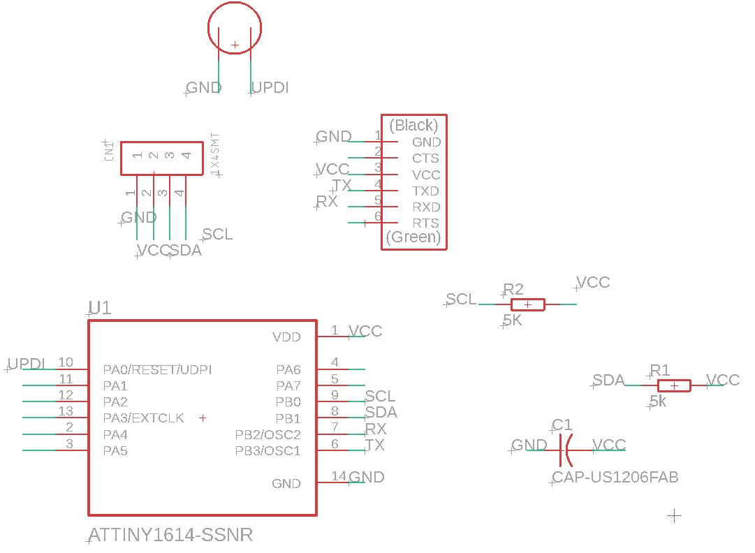
As a starting point I had to list down all components needed to draw the PCB. ATTINY1614 was used, however i was not able to find the exact footprint in eagle software. so I had to download the library that provides the exact footprint.
Once all components were specified, the connections were made as shown below
Download link for ATtiny1614 Library
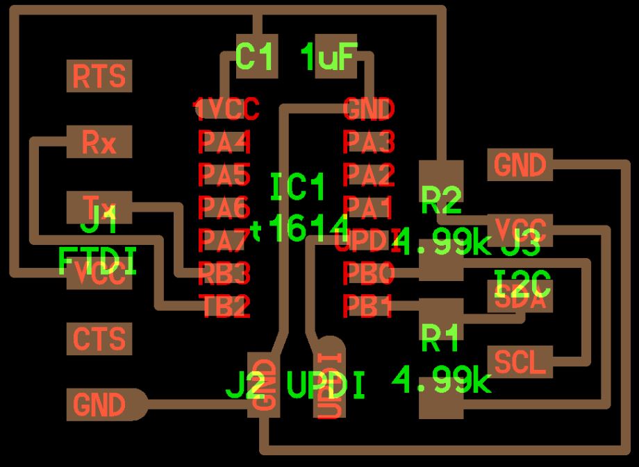
- After creating the connection, next step was to start the routing process. The result was as the following

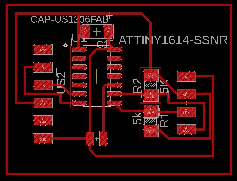
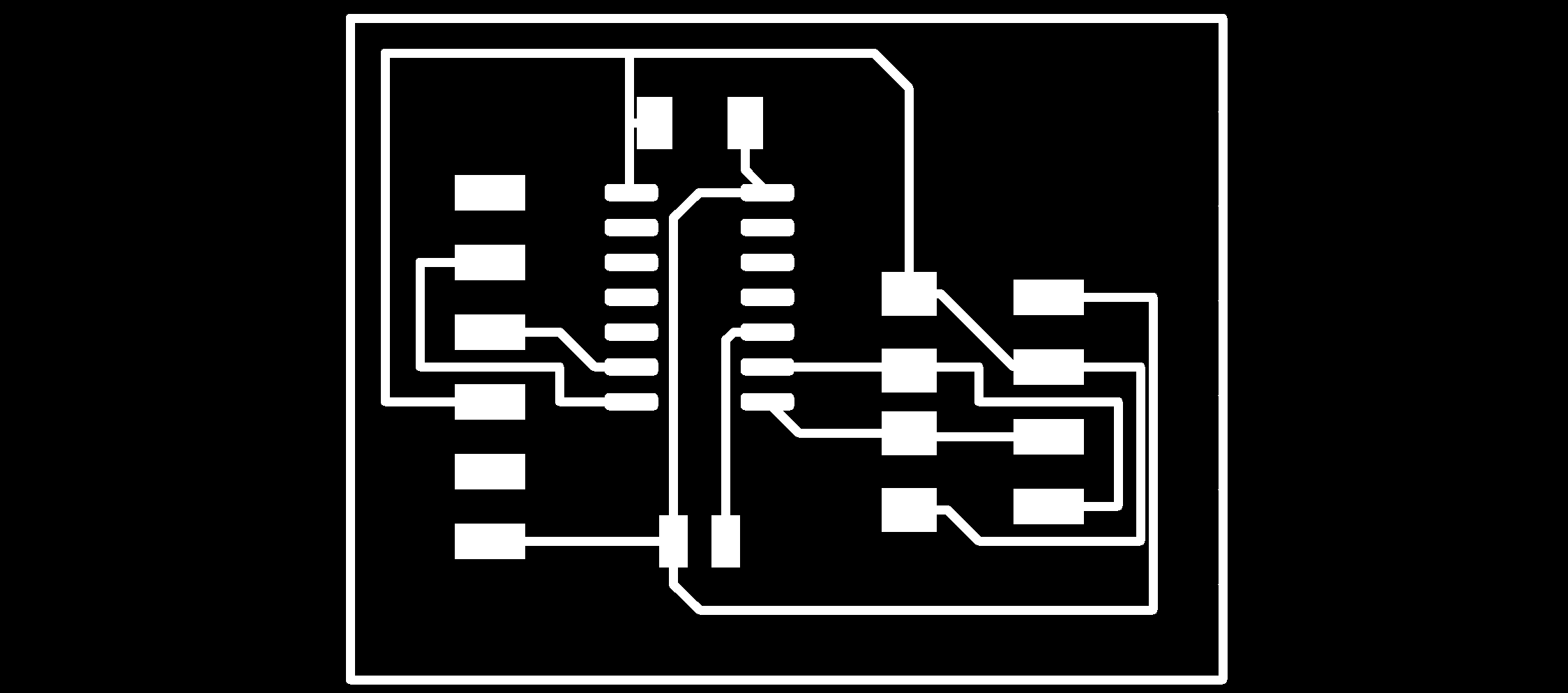
Click on text below to download Eagle File:
- - LCD Display Board Eagle schematic folder
Programming and Testing
- At this stage I had PCB design ready to be uploaded to the Roland machine and produced. Howeve because of COVID-19 I did not have access to the Fablab and it was very difficult to perform the PCB production and Soldering.
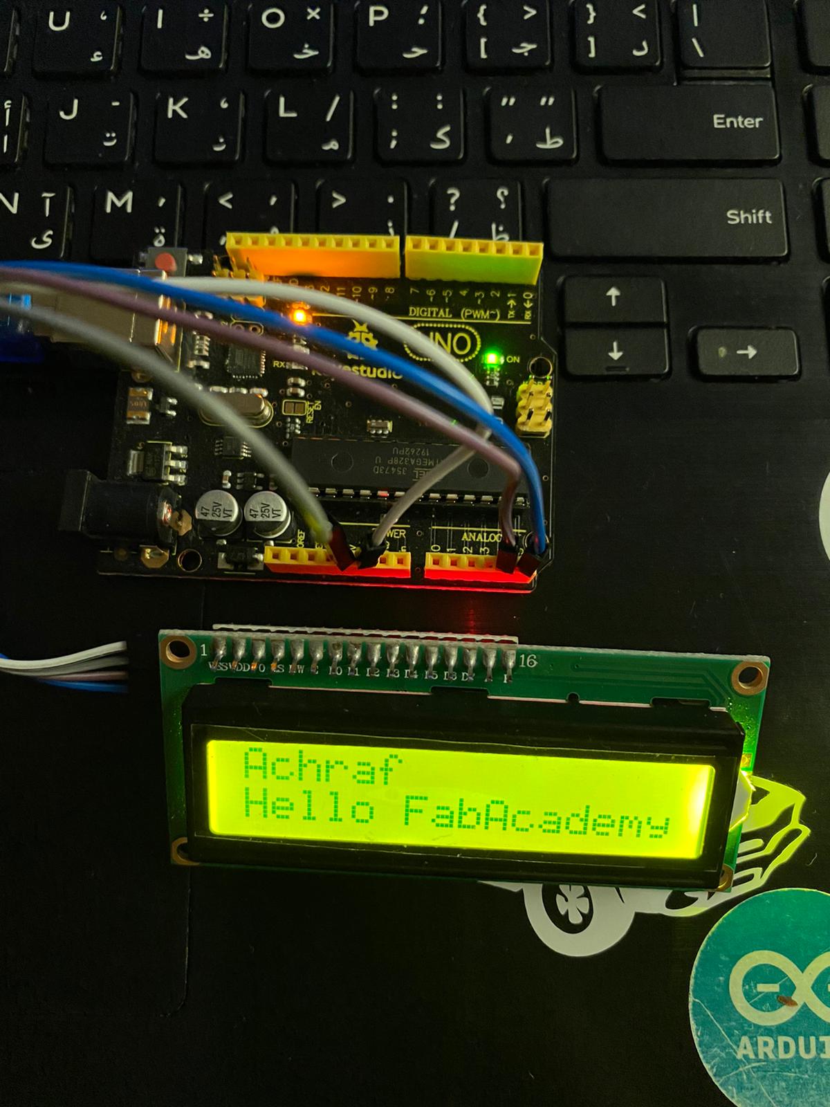
Fortunately, I had the option to use the Home electronics kit that was provided by our Lab instructor. Programming the Arduino was very fun and much simpler than programming the PCB.
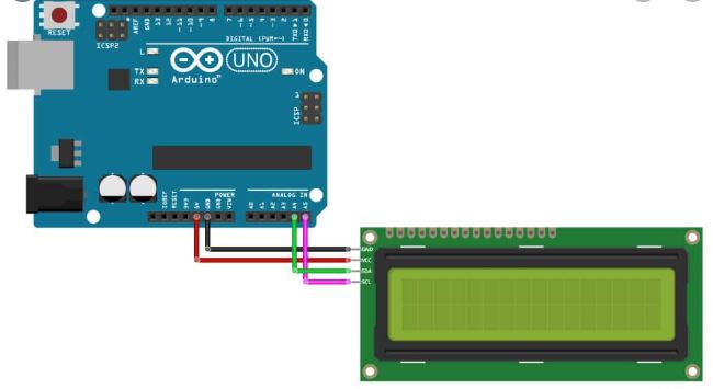
Below shown the list of items I used:
- Arduino KeyStudio
- LCD IC2 Display
- connecting wire and USB wire.
I have made the connection between the items as the shown schematic.
- Once the arduino connection was made, the next stage was to start programming the board. I made multiple researches on the Internet about the programming process, I have I found out that its very important to add new liberey to the Adrunio IDE software and specify the Unique Address of the LCD IC2 display.
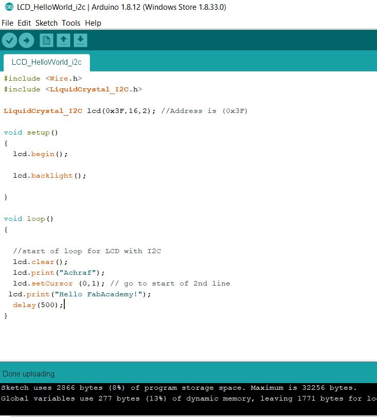
- As a final step, I had to click on Verify and made sure there was not error, the I clicked on Upload for the program the Run.