Input Devices
Tasks for this week:
- Group- Probe an input device's analog levels and digital signals.
- Measure something by adding a sensor to a microcontroller board that you have designed and read it.
Part 1- Group Assignment
Due to COVID-19, our main lab was closed. We were unable to complete this week's group assignment.
This page will be updated soon.
Part 2- Using a Potentiometer and Flame Sensor
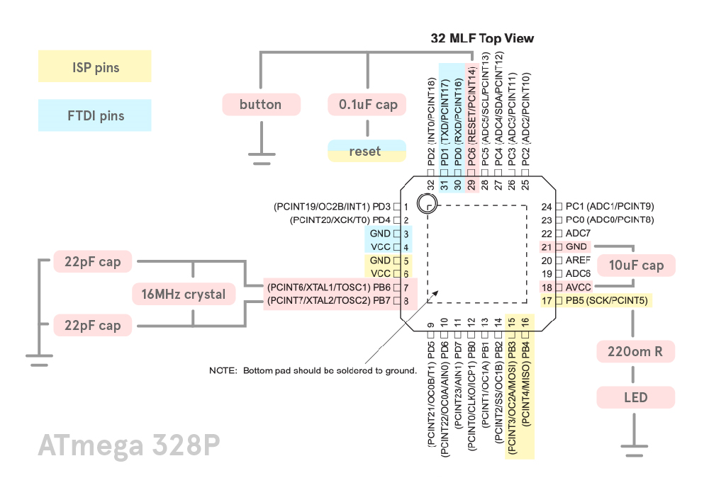
Our individual assigment this week calls for us to measure something by adding sensors to a board we have designed. Now, the board that I designed in the Electronics Design week (Echo Hello-World Board) could have been used for this assignment, as the ATtiny44 chip had 3 unconnected pins. This would have allowed me to add a sensor and read it. However, I decided to design my own Arduino version, that can be used in multiple assignments. Designing this would take some time, so I decided to follow this tutorial on Arduino's website to make an ATMega328 Arduino on a Breadboard. Breadboards are not really recommended, but it helps present components and connections out in a clear and efficient way. However, it still is a board that I have designed, and I can add a sensor to this to complete this week's assignment, whilst I continue to design my own version of Arduino.
The list of components I used for this breadboard version is identical to the actual Arduino board:
- ATMega328
- 16 MHz Crystal
- 22pF Capacitors
- 10uF Capacitors
- 499 ohm Resistors
- 10k ohm Resistors
- LEDs
After double checking all connections, I burnt the bootloader through Arduino IDE using a FabISP. Initially, the board was taking longer than expected to respond, but then the bootloader was uploaded successfully. One thing to note is that the programs won't be uploaded through an FTDI connection unless there is a capacitor between the ATMega32 and the Reset pin of the FTDI. This is because there is a difference in communication speeds. We need to slow down the by adding an extra 0.1uF capacitor.
In Arduino IDE, I opened the AnalogReadSerial example code, and after this was uploaded to the board, I connected a potentiometer. As the potentiometer is turned, the values on the serial monitor progressively increase from 0 to 1023. It is actually quite precise as well. The video demonstration of this input device is shown here:
Another sensor I used in this week's assignment was the flame sensor. I connected it to my board, and started the serial monitor. Using a lighter, the closer the flame was to the sensor, the higher the value registered on the serial monitor.
Later, when I tried testing the sensors again, I started getting errors! The error I got was "COM 4 Not Found". I ensured that all the connections were correct, and none had fallen off in transport. I then double checked the COM ports, tried using a USB extender, but I could not debug the problem. This was a major problem, as I had not recorded the videos of the input devices working yet. When I opened the device manager on my laptop, I noticed that the ports would only be visible when the 'Show Hidden Devices' feature was on. This led me to believe that there was a problem with my laptop's port, so I tried uploading using a different laptop and it worked! Problem solved, except I now have a new problem with my laptop. :(
Part 3- Producing My Version of Arduino
I used the Satshakit board as reference to my design. It took quite a while to understand the schematic of this board, as it was my first time working with the ATMega328i, therefore it is the most complicated board I have worked with. The layout of the board is highly complicated, especially because several modifications have been made to improve the board.
My board started by using the following components:
- 1x atmega328
- 1x switch
- 2x 22pF capacitor
- 4x 0.1uF capacitor
- 1x 10/100 uF capacitor
- 1x 10k resistor
- 2x 499ohms resistor
- 2x LED different color
- 1x 16mhz crystal
- 2x 1X6 pinheader
- 1x 1X9 pinheader
- 1x 2X3 pinheader
One of the most useful pictures I used were the board layouts, which showed the most relevant pins that must be connected.
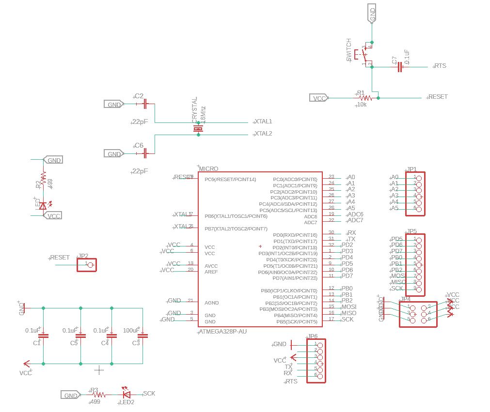
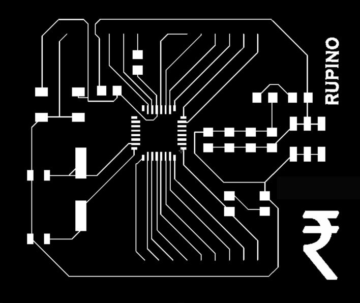
 I added all the components from libraries in Eagle, then started making connections. I kept using the Satshakit schematic as a reference for the components, but two things I wanted to change was the placement of the pins, and add more GND and VCC pins to add more input and output devices at the same time. Then, I converted the schematics to a board design, and started creating the best layout. I ensured that the FAB DRC design rules were followed, and checked that no traces were too close to each other, or that the traces for the crystal were equidistant from the microcontroller. The following images show my schematic and board design:
I exported the board design file, and opened it up in Photoshop to add the name and logo. I named my board Rupino, after the Indian currency. Then, I milled the board using the processes I documented in Week 4. I cleaned the traces using a tweezer, then scratched with steel wool to improve the finish of the board. Finally, I rubbed some alcohol over the entire board, especially the area of the microcontroller traces. Now, I could start soldering.

I collected all the components to be soldered using the list above. Then, I began soldering the microcontroller. The ATMega328 has tiny legs very close to each other, and this was the hardest thing to solder. No matter what I tried, solder would get stuck between 2 pins, and it would be impossible to remove with the vaccuum pump. I learnt the new technique of using the solder braid, which worked in removing solder, but under a magnifying glass, I could still see that it was not completely removed. The only method that worked was using soldering paste. After the microcontroller chip was soldered on, the rest of soldering was quite easy, and I quickly soldered all the components on. Finally, it was time to upload the firmware, and when burning the bootloader, I got errors. My board was not responding; this was the error I got;
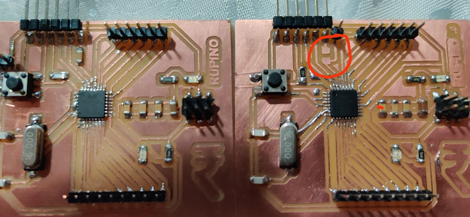
 I then tried to upload something using the FABISP without burning the bootloader, and then I got another error, which asked me to double check my connections. I did so, and noticed that 2 legs of the ATMega328 were still connected. After I desoldered them, I tried again, and got the same error. It was at this point that my instructor pointed out that I was using the wrong reset pin; I had connected it to the FTDI pin, which can't work. I realized that I didn't have a propietary reset pin, so I soldered an extra pin to the switch, which was connected to the reset trace. I reattempted uploading the bootloader, but to no avail. I started re-evaluating my schematics, which allowed me to realize another problem. I had labelled on my schematic all the GND and VCC pins, but I realized that those were merely labels, and that they were not remotely connected. At this point, I decided to make another board.

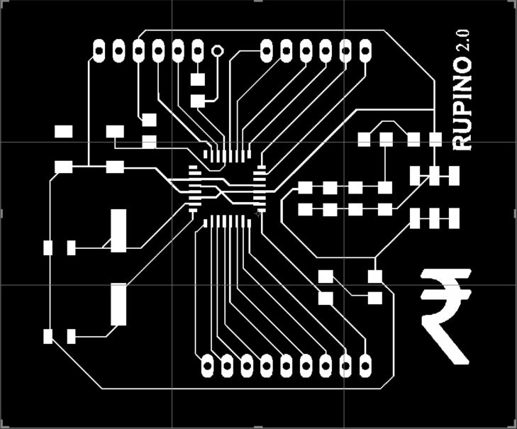
The development of the Rupino 2.0 began by adding a reset pin and connecting the GND and VCC pins of the microcontroller to their respective traces. I followed the same procedure as before to prepare the traces for milling, then soldered the components on. Hopefully, this new, improved board would work. Making sure that all connections were correct, I re-attempted uploading the bootloader. And initially, the computer would not recognize my FABISP. Eventually, it did register, but when I uploaded the bootloader, I got the same error as before. Check connections. My instructor suggested uploading the bootloader while selecting the board as an Arduino Pro or Pro Mini. This worked for a student last year, but it didn't work for me. Now, I am getting errors, that the expected device signature for the ATMega328 is not registered, which leads me to believe that there is a problem with the microcontroller chip.
So far, I have not been able to debug the problem. I have tried rubbing alcohol onto the microcontroller pins and traces, cleaning them, and inspecting the microcontroller connections. With a multimeter, everything appears to be fine. One thing I did notice was that I forgot to solder a capacitor for the FTDI reset connection onto my second board, but this should only have an effect on uploading with FTDI, not the process of burning the bootloader. I will keep debugging, and if nothing works, I will make a third board.
 Updates will come soon.
Update: I finally got a working Rupino after numerous failed attempts. Since I didn't have a flame sensor with me anymore at the time of writing, I used a potentiometer connected to my Rupino as an input device, and I linked it up to a processing interface I made for the Interface and Application Programming week to demonstrate it working (see that week's page for code). Here is the result:
I did face one error whilst uploading the code to my Rupino. For some reason, it was just not communicating whilst uploading; it would simply fail immediately. I later figured out that there was an issue with my schematic, so for FUTURE REFERENCE: swap the TX and RX jumpers on the FTDI connections, and it should work.
Click here to download the AnalogReadSerial Arduino Code