
Week 5 Electronics Production
This week is a start of electronics. I am very excited about it. Circuit is brain of the systems. I know it will takes years to master.
Weekly Assignment
- group assignment:characterize the design rules for your PCB production process
- individual assignment:make an in-circuit programmer by milling and stuffing the PCB, test it, then optionally try other PCB processes
Group assignment:
Shayas did the group assignment link.
PCB fabrication:
Etching is traditionally the process of using strong acid or mordant to cut into the unprotected parts of a metal surface to create a design in intaglio (incised) in the metal.[
Lithography is a method of printing originally based on the immiscibility of oil and water.
SDS are materiel safetysheet.
Chemical way of PCB fabrication will waste a lot of water.
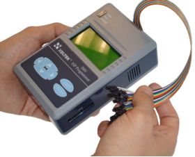
What is FabISP?
In-System programming (ISP), also known as in-circuit programming (ICP), it allows programming and reprogramming of microcontrollers, serial EEPROMs and flash memories already soldered on a target PCB.
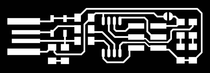
1 Obtain the files: Find a Circuit Board
Export/save your board design as .png, You should have two or three images, depending on your PCB:

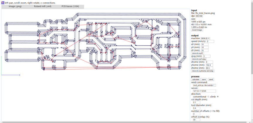
2 Set machine paths by Fabmudules:
Fabmodules is a online program to calculate the machine paths and set input and output to milling the board.
** 0.4mm Tolerance of Circuit Design: Circuit should have a gap of at least 0.4mm between each path/element on the board.
3 Milling the board
Use double side tape for fixturing the board on underlay. Turn on Roland Modela and the computer and open VPanel for SRM-20,A nice tip is to warm the spindle for 10 min at mid Rpm before using it.
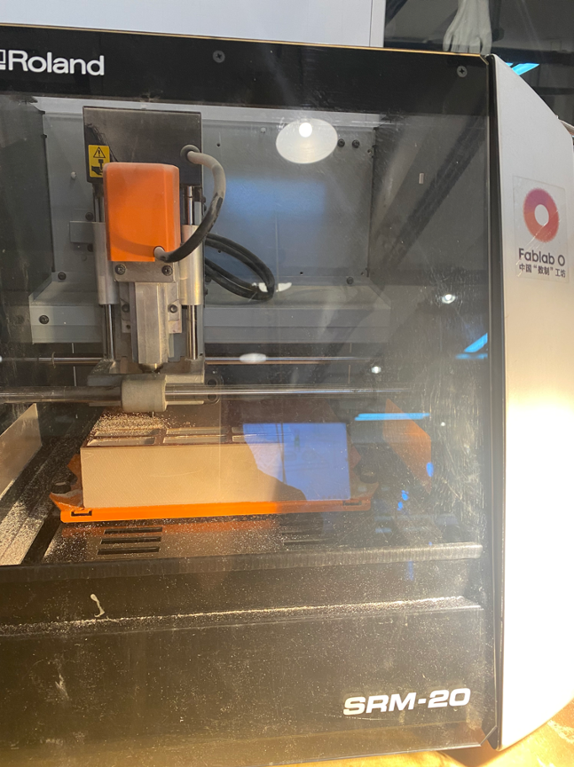
Use“sacrificial board” so you don’t mill the own machine.Make sure it’s steady and flat.
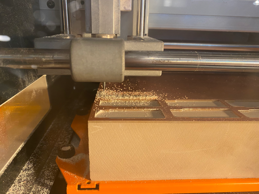
Change mill: 1/32 inch bit is for cutting out board,1/64 inch bit for milling trace; Set the X/Y/Z zeros; Send the traces and send the outcut/holes.Set XY ,and Z for end mill.
4 Soldering the board
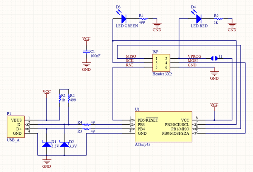
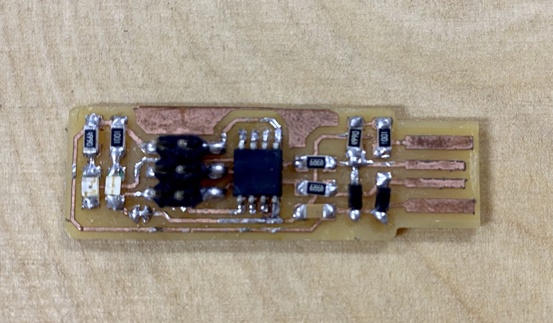
Use tweezers and brush to clean and remove glitch.Then soder components below:
- 1x ATtiny45
- 2x 1kΩ resistors
- 2x 499Ω resistors
- 2x 49Ω resistors
- 2x 3.3v zener diodes
- 1x red LED
- 1x green LED
- 1x 100nF capacitor
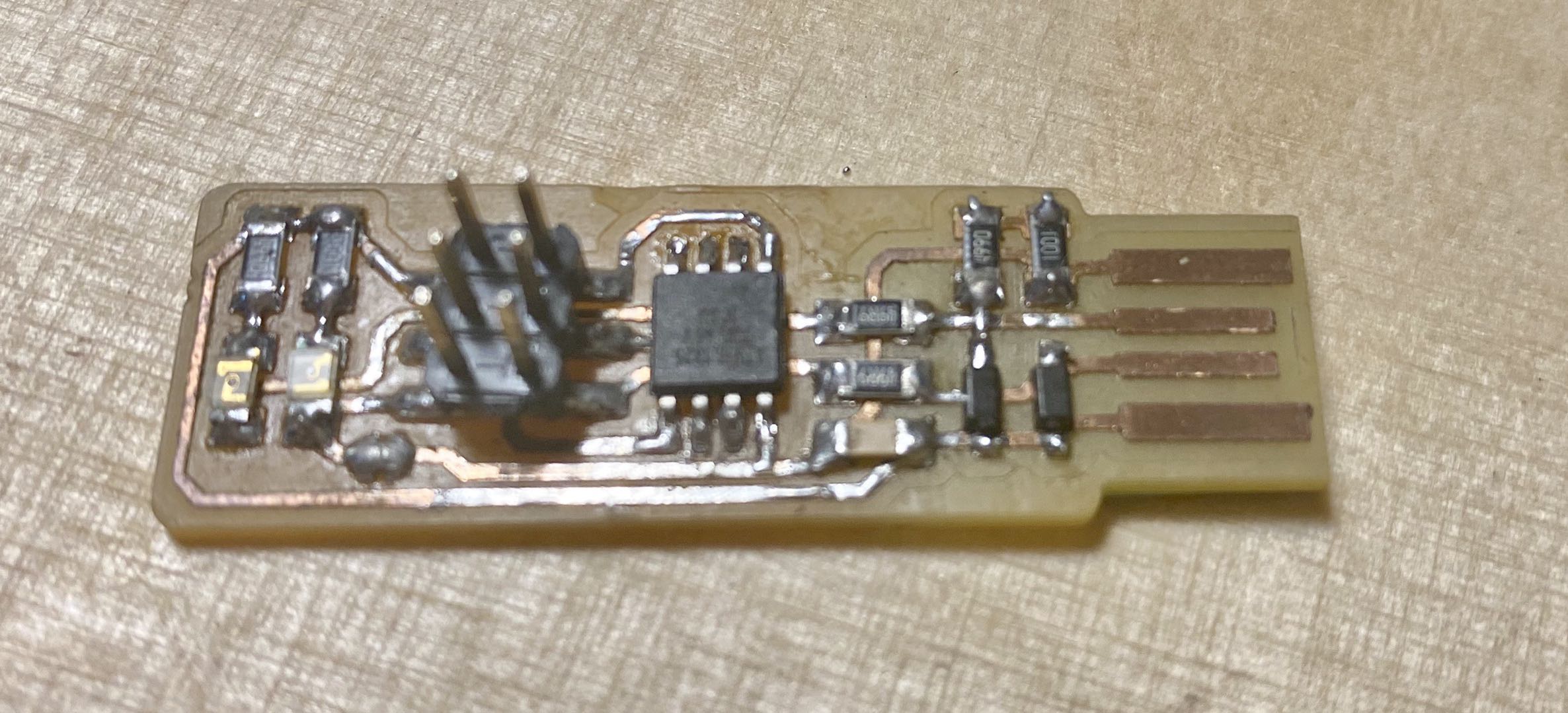
- 1x 2x3 pin header
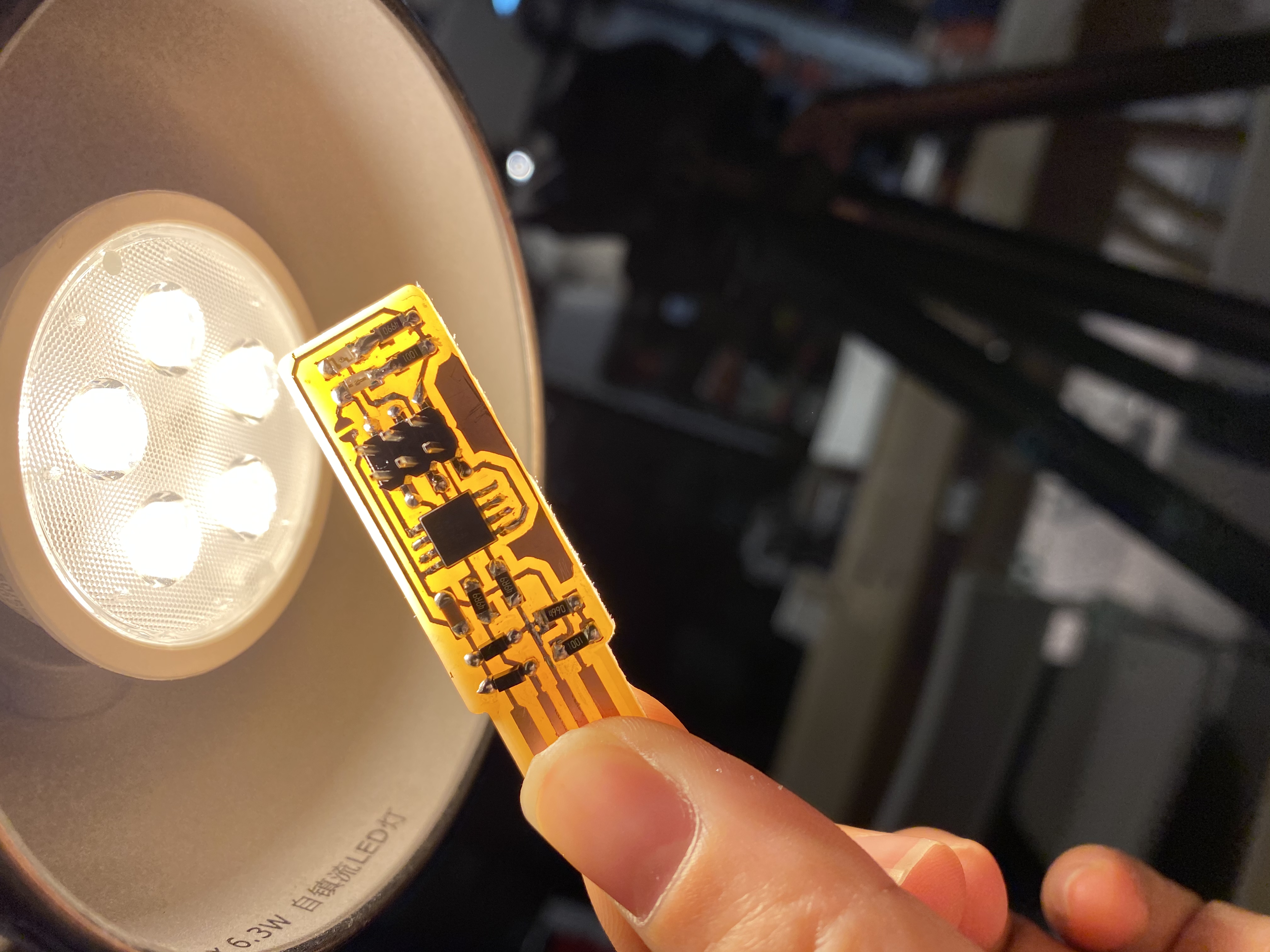
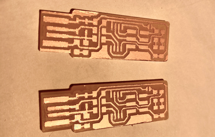
However, my first FAB ISP doesn't work somehow. Proberbly because my bad soldering.
First one: failed.
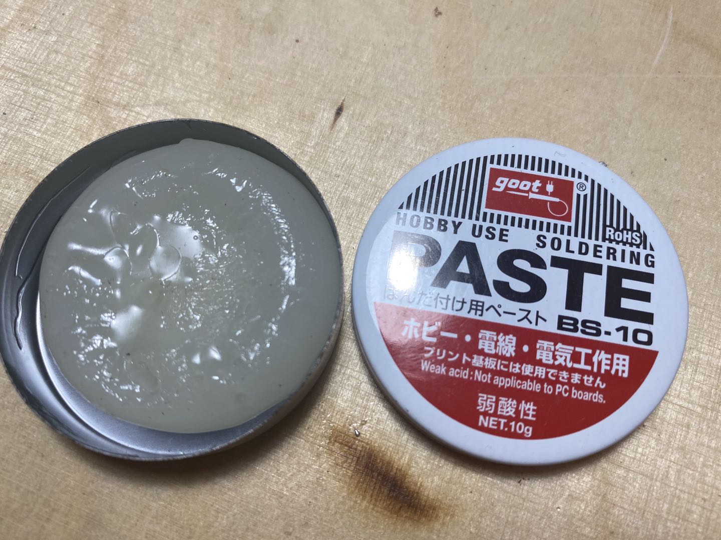
Second one: I use a wider soldering iron which works better to solder chip. I also use solder paster that could help soldering tin stick to copper lines.I also use a multimeter to check for shorts between VCC and GND.
4 Software Installation
- Set up development environment for my laptop. Download CrossPack CrossPack is a development environment for Atmel’s AVR® microcontrollers running on Apple’s Mac OS X, similar to AVR Studio on Windows. It consists of the GNU compiler suite, a C library for the AVR, the AVRDUDE uploader and several other useful tools.
- Download thefirmware source code
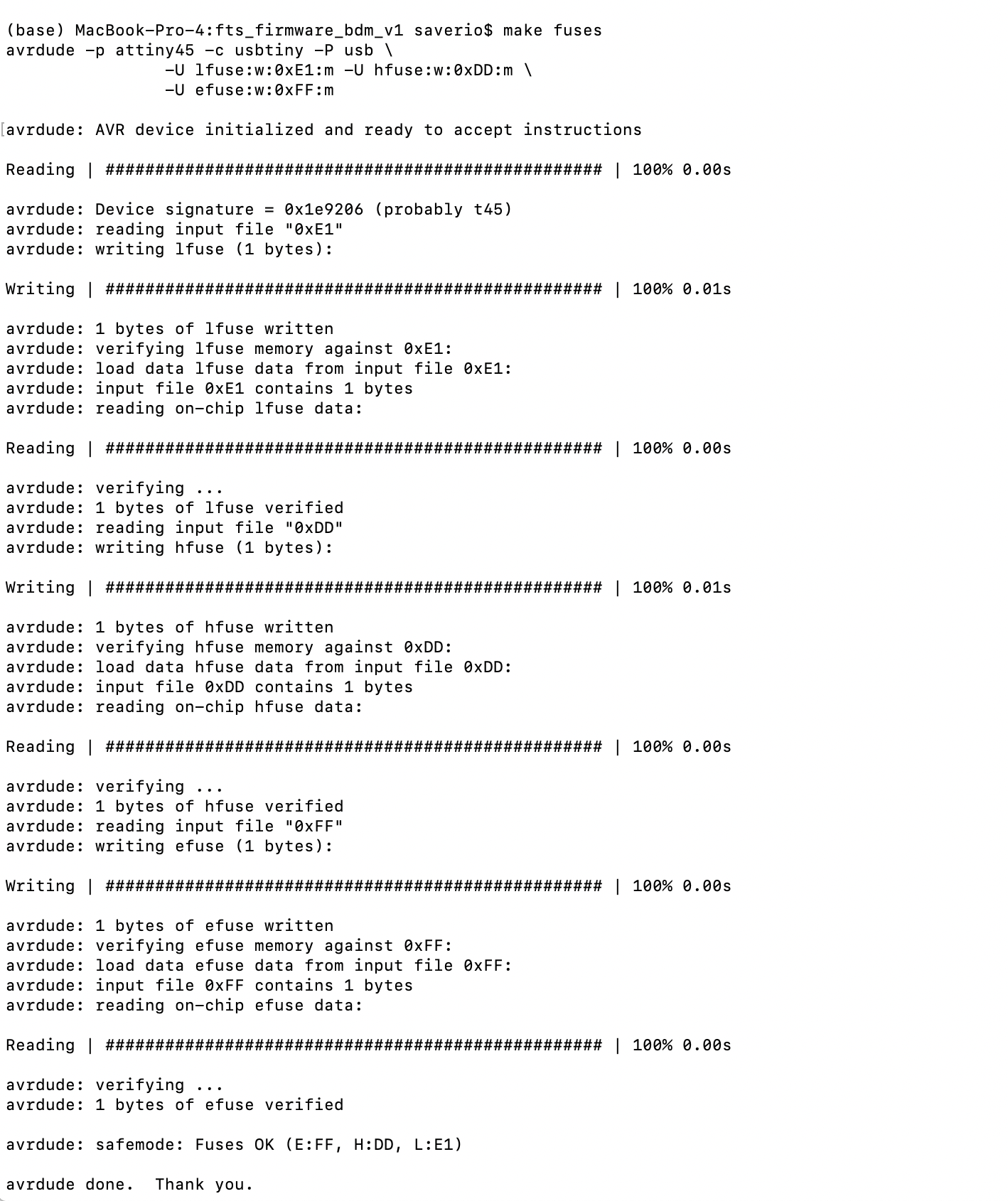
5 Get and build the Firmware
Download the firmware source code and extract the zip file
Connect ISP to laptop: