![](images/banner.jpg)
Design PCB for my final project:
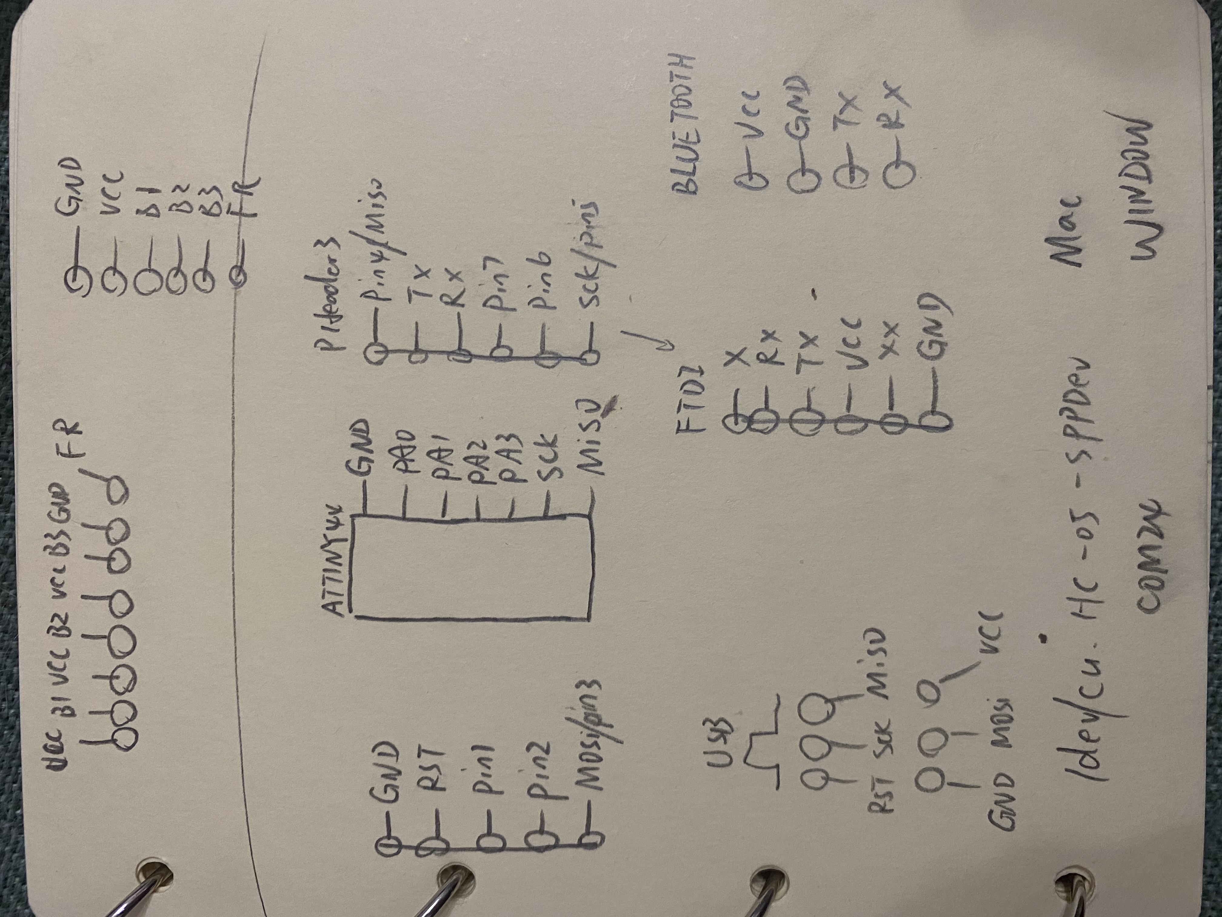
For my final project I need to have 3 buttons and one force resistor as input, bluetooth as output. So I draw the schematic on paper first
![](images/week09/06.jpeg)
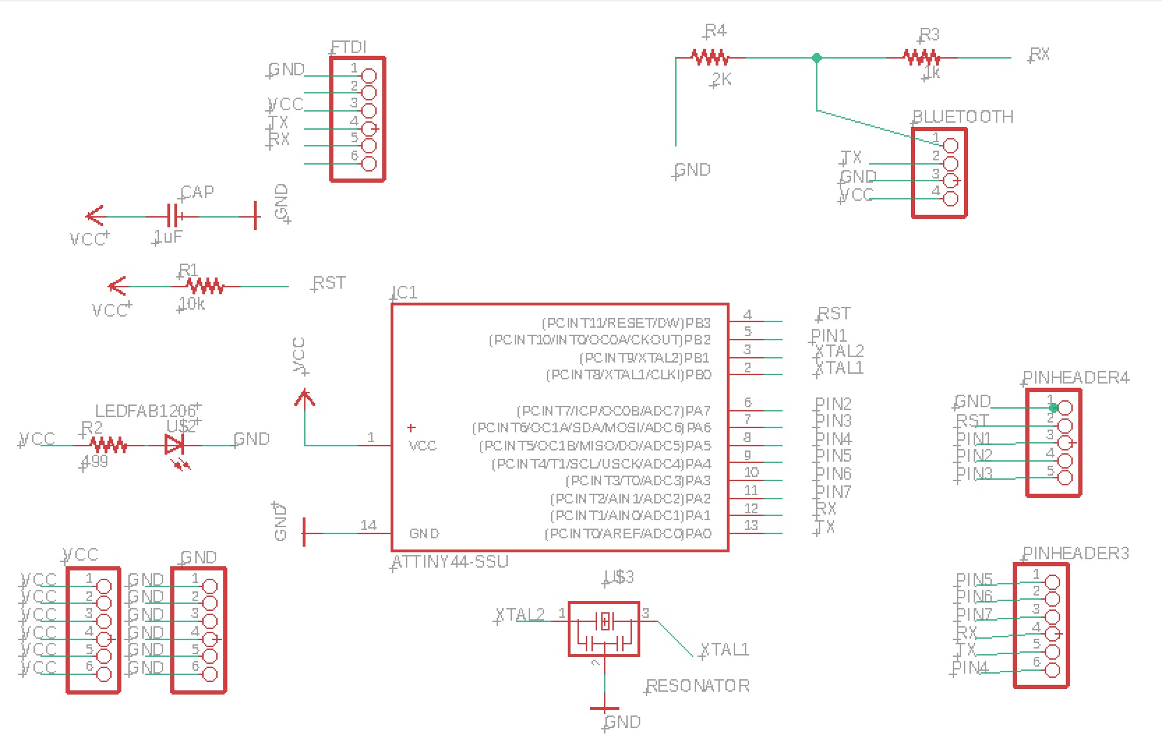
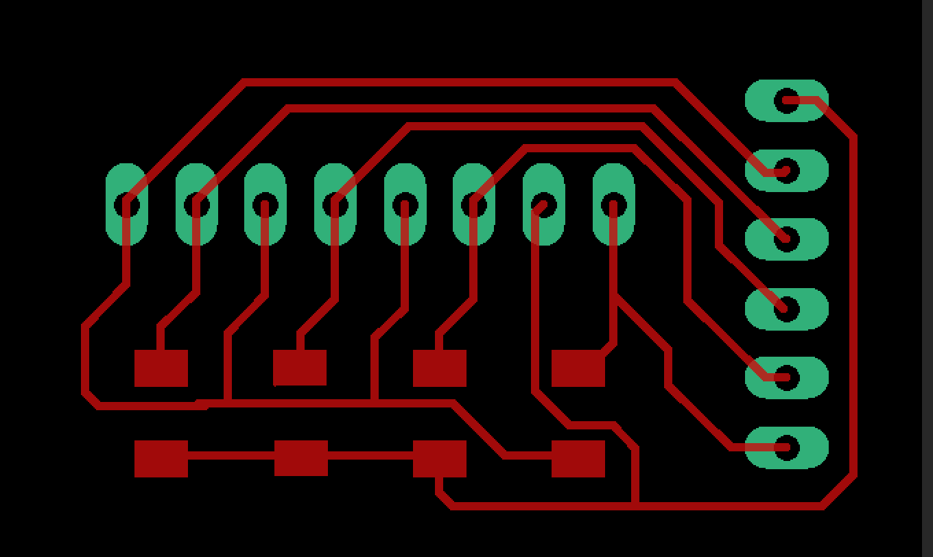
Then I draw it on Eagle. Make sure it has enough pins for buttons, FTDI, bluetooth.
![](images/week09/Gino2.jpeg)
![](images/week09/gino1.jpeg)
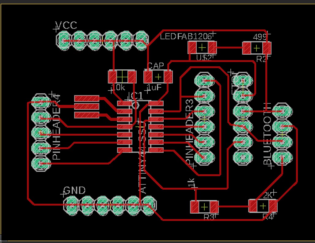
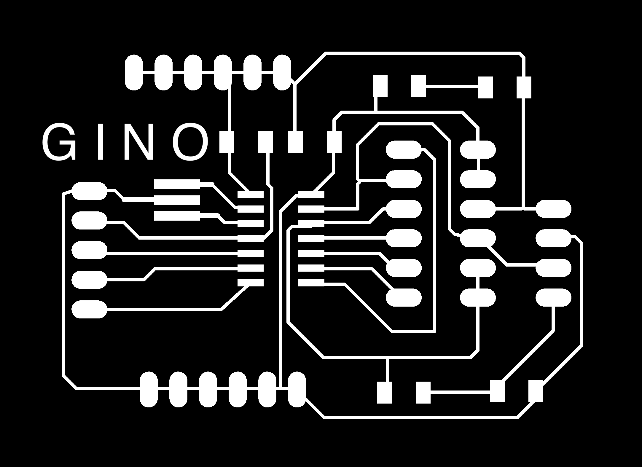
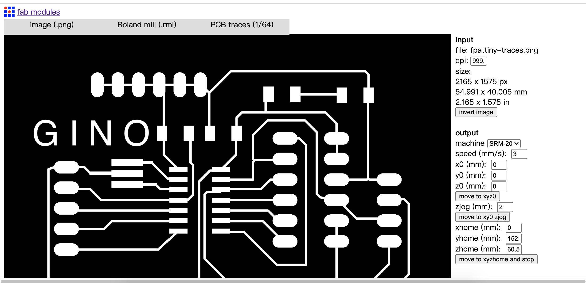
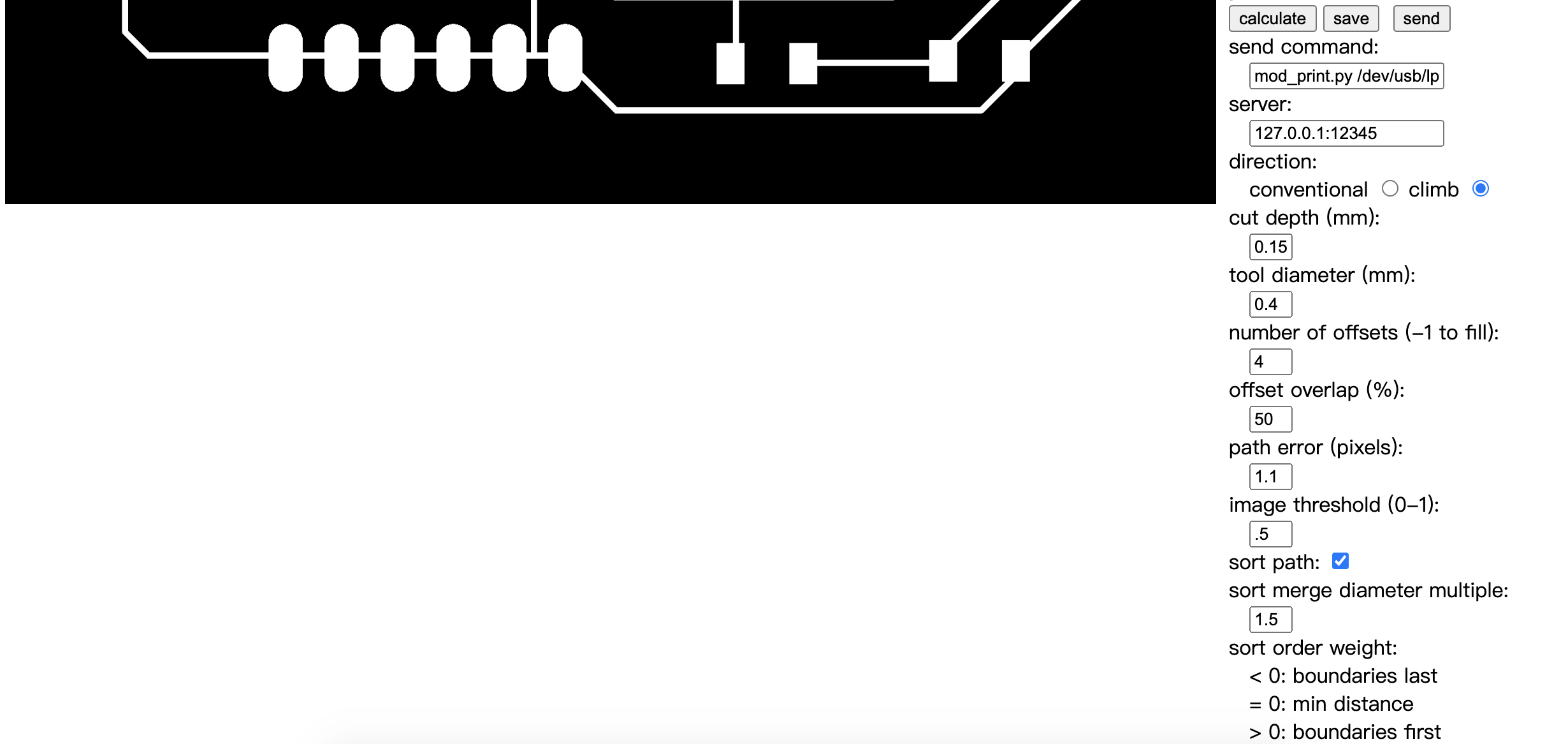
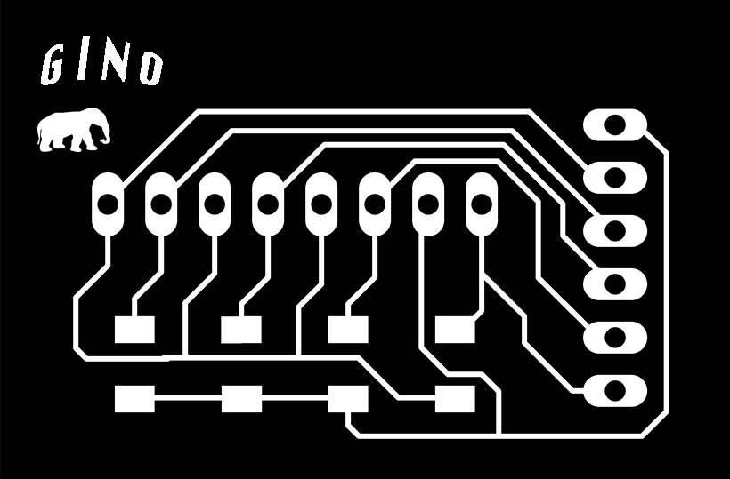
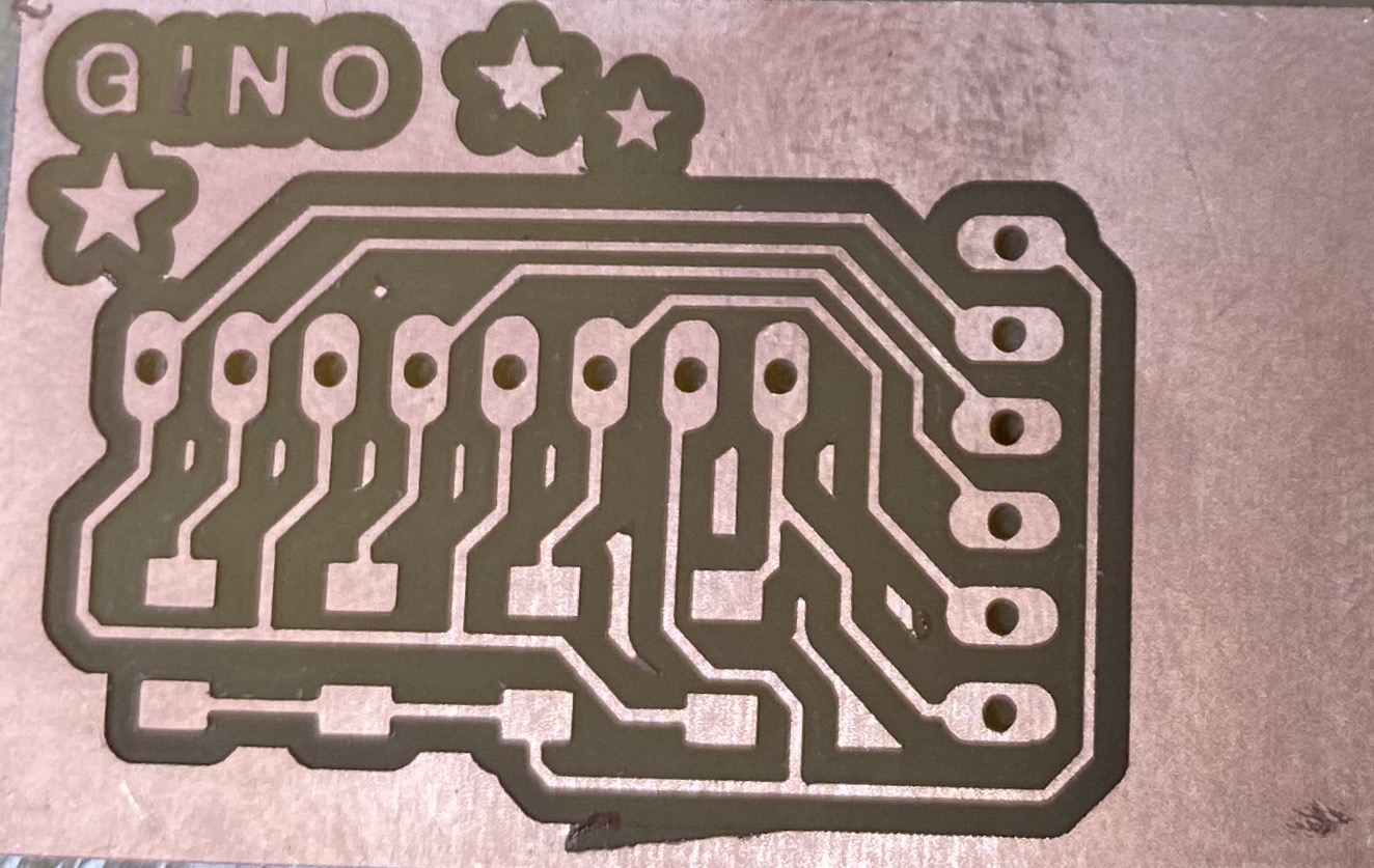
Then I make the milling trace for GINO board.
![](images/week09/fpattiny-traces.png)
![](images/week09/fpattiny-outline.png)
![](images/week09/fpattiny-holes.png)
I use fab mudule to creat path for CNC. The setting is below.
![](images/week09/milling.png)
![](images/week09/milling2.png)
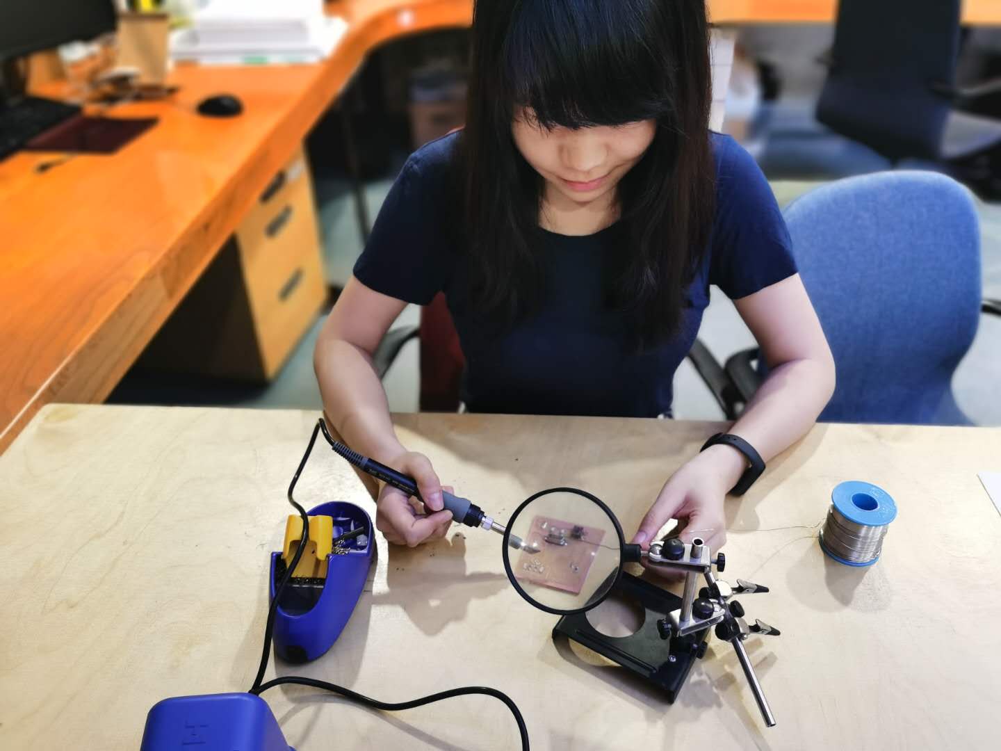
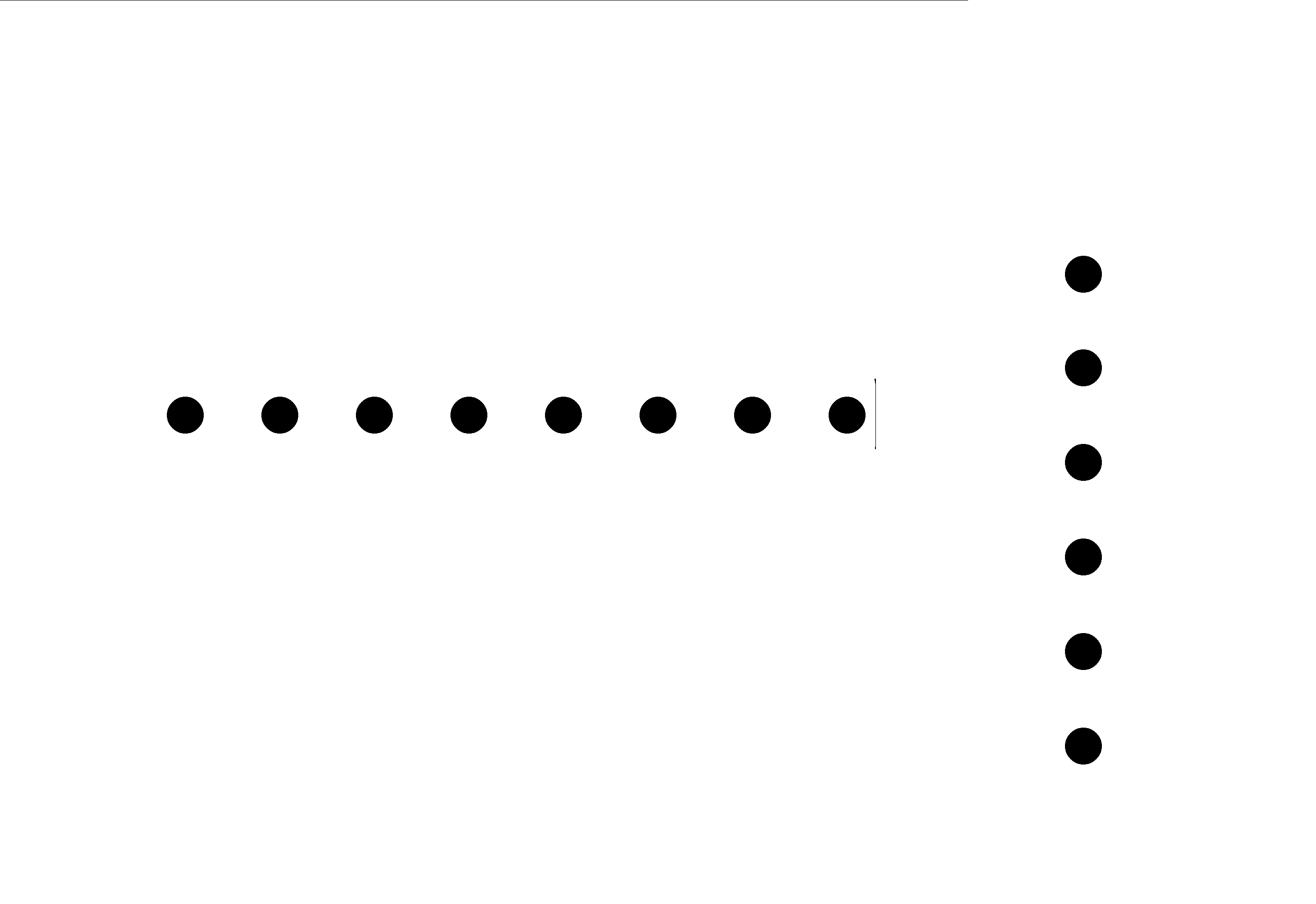
I also make a board for force resistor and then milling it.
![](images/week09/WechatIMG14的副本.jpeg)
![](images/week09/freagle.png)
![](images/week09/frtrace的副本.png)
![](images/week09/frtrace2的副本.png)
![](images/week09/frholes的副本.png)
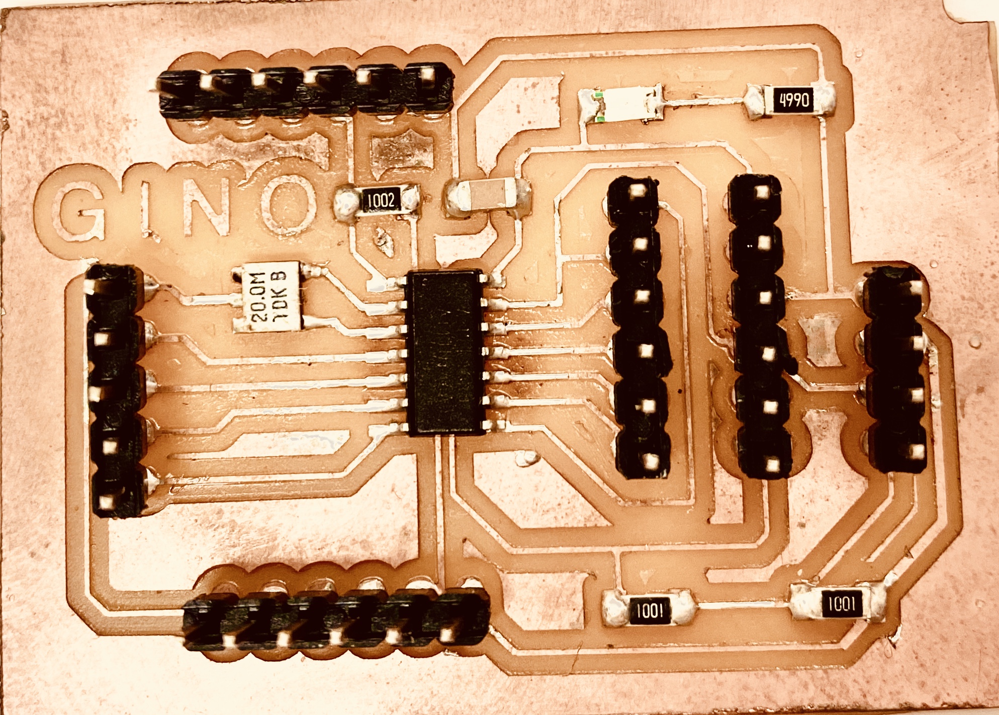
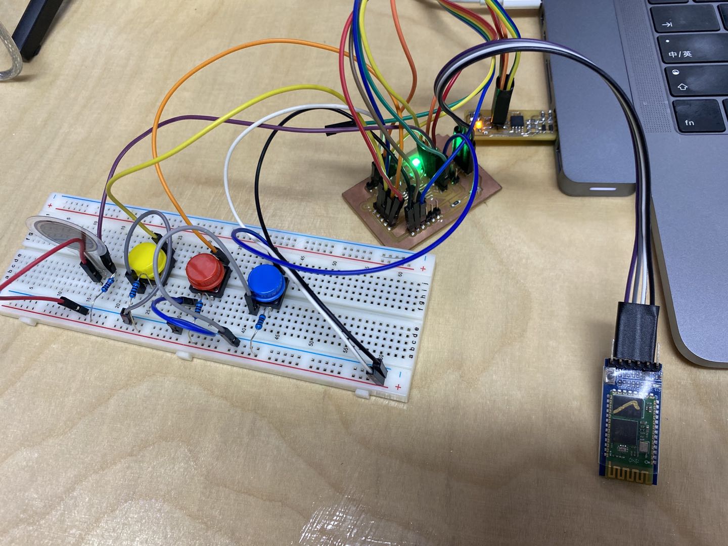
Final project board:
![](images/week09/WechatIMG12的副本.jpeg)
![](images/week09/WechatIMG15的副本.jpeg)
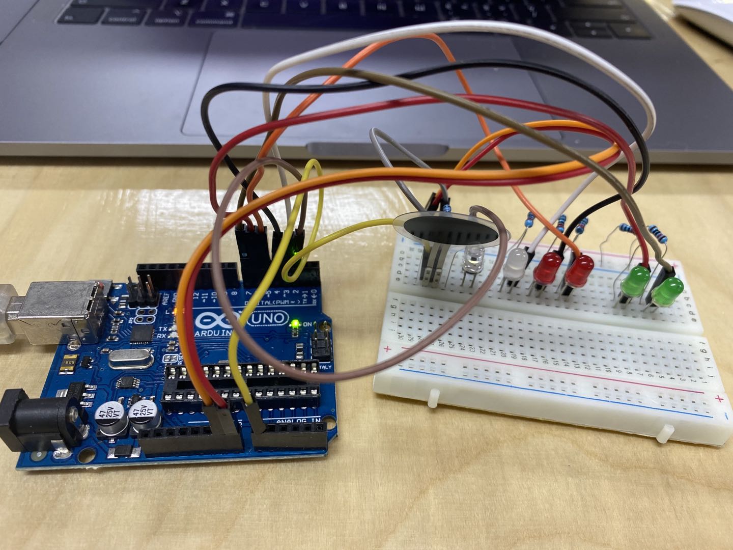
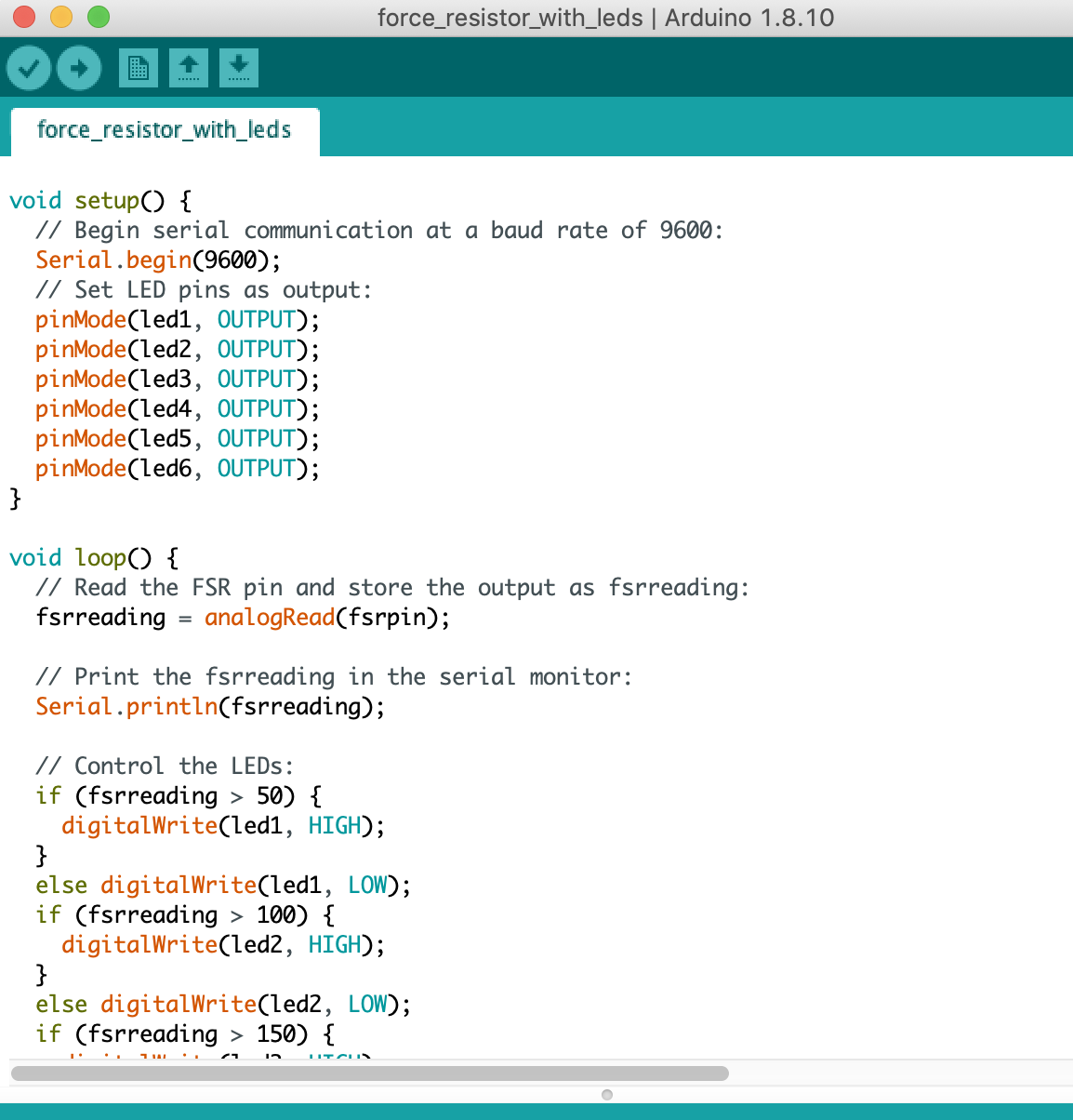
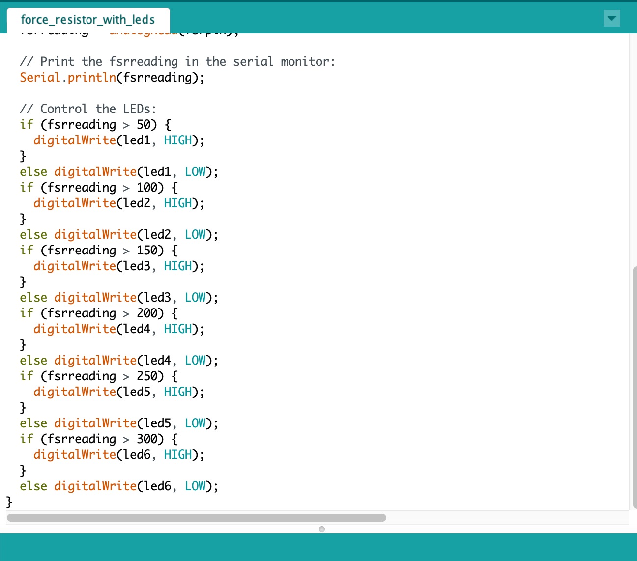
1 Try the force resitor with leds.
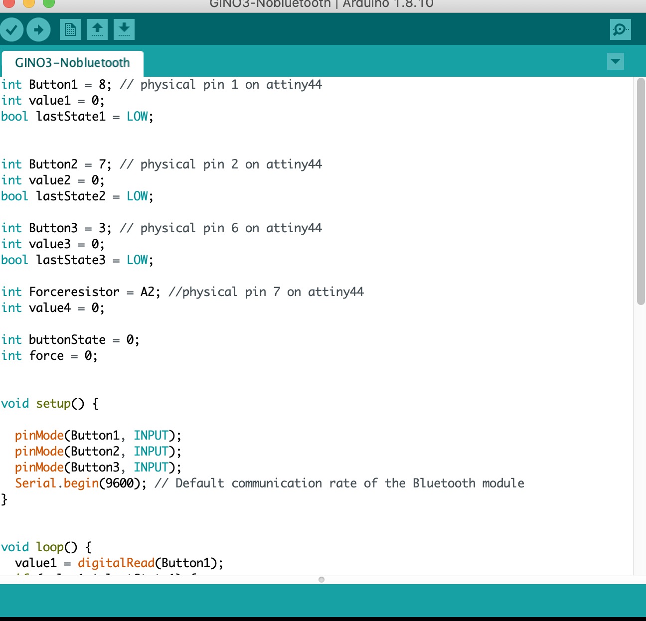
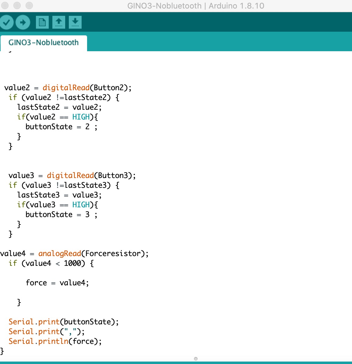
![](images/week09/test.jpeg)
Code is below:
![](images/week09/ledtest1.png)
![](images/week09/ledtest2.jpeg)
![](images/week09/test.jpeg)
Try to use with buttons with force resistor. The code is below:
![](images/week09/test2.jpeg)
![](images/week09/buttonnoblue1.jpeg)
![](images/week09/buttonnoblue2.jpeg)
![](images/week09/buttonnoblue3.jpeg)
Test video: