3D Scanning and Printing
Federico, 26 February 2020
The assignments of this week were:
- group assignment:
- test the design rules for your 3D printer(s)
- individual assignment:
- design and 3D print an object (small, few cm3, limited by printer time) that could not be made subtractively
- 3D scan an object (and optionally print it)
Link to the lesson. Link to the videolesson.
Designing a Earphones holder
I wanted to create my very own earphone holder so I started drawing one in Fusion360. I tried to sketch on the notebook something in order to print less material. I started drawing a simple geometry like this , with a 2 point rectangle at the origin, then I created some fillets.
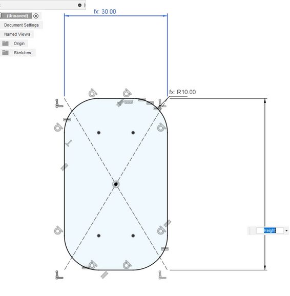
Then I started drawing an inside structure that doesn’t allow to lose the earphone from one side, but using less material. In order to accomplish that , I used the offset function:
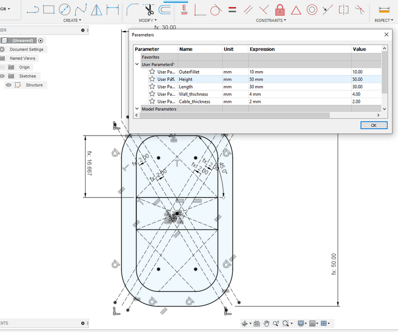
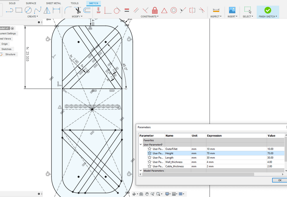
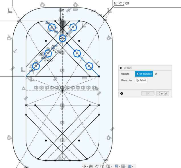
Here is very important to define the parameters. In this way you can always do litte changes if you have some particular earphones. I needed to be very carful while mirroring things, I had to select points and remove some costraints that gave me problems:
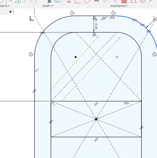
Then I tried if my parameters worked well , there were be multiple times that at this point something was not working. The design has to update according to the given parameters. I think that for a parametric design this is a check that should be done very often. As you can see here this is not working properly as the center cross it’s not centered with the origin of the component.
It’s important to draw slant lines and pay attention to don’t let them get constraints that could generate you costraints errors.
After that point it’s very important to have at least the base sketch defined, it’s very not recommended to go further this point is it’s not everything well-configured.
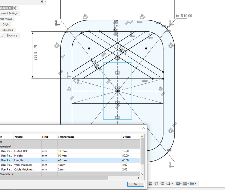
I also checked if the lenght parameter were working the way it should.
As you can see in order to not waste time I first checked everything was working and THEN I mirrored through the x axis. I was wasting so many time in mirroring everything without seeing if the parametrization was working properly. So I had to redo this many times.
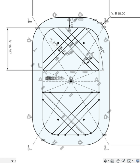
At this point I started creating some small geometric holes (for the sake of easthetics and material wasting) before the mirror. I let the distances between them to be equal with small non-construcion lines.
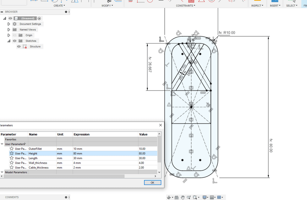
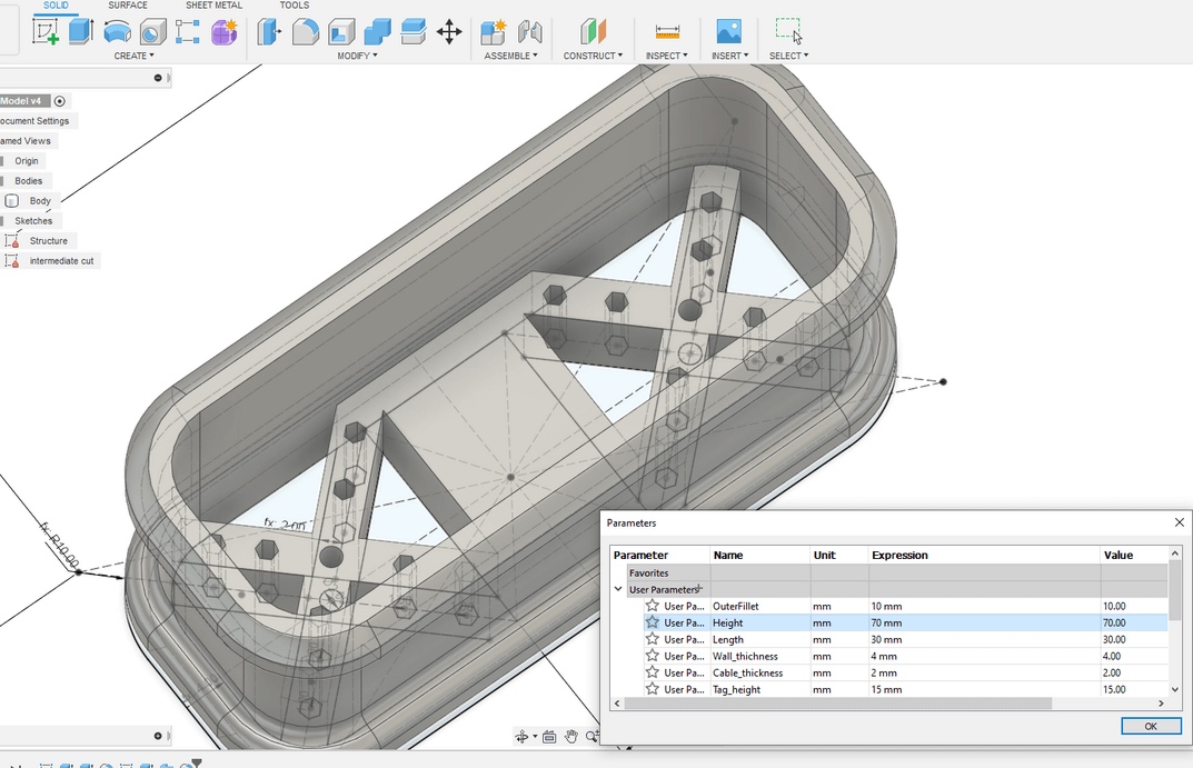
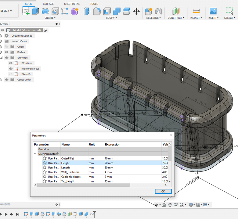
At this point I figured out that the height of the central tag was giving me some problems, so I redesign the tag in order to let his height to be configurable:
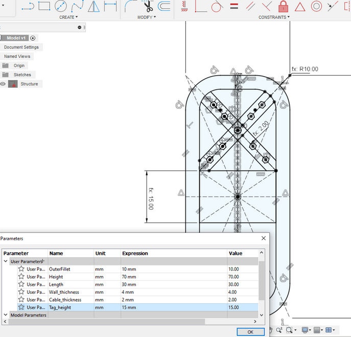
In that way the design has two measure constraints: Height of the entire component should be greater of twwo times the offset of the outer geometry plus the central tag. Obviusly , these is an extreme coonstrain. We also have to consider that there are the diagonal crossing line. So if we want to achieve very small pieces , we can decrease the overall offset. ( I let it configurable)
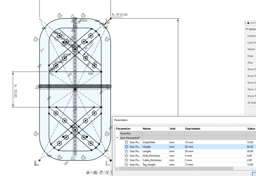
Once I defined the entire sketch I , tried another time if the parametrization was working, and it worked like a charm!!
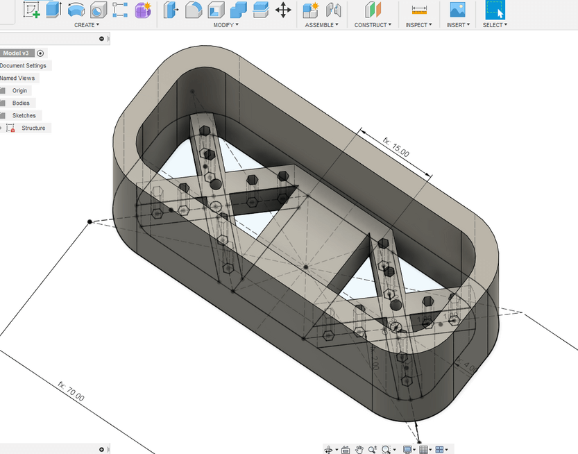
Now that everything is setup, it’s time for z axis extruding! So I added to more parameters, one for the internal height and one for the outer walls, the I simply extruded selecting the right geometries.
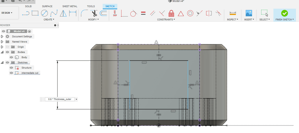
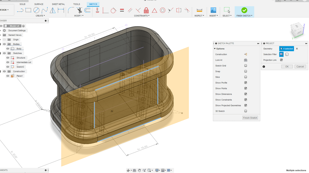
I didn’t wanted to let my holder to destroy my cable so I thought that the central part of the holder has to be curve inward. So I started creating a construction plane attached to a face and I projected some reference lines to this plane.
At this point I started projecting the construction line in the construction plane and I draw a parametrized rectangle. to define parameters I always use percent parameters of something else ( in this case I used the 60 % of the outer thickness). In that way I’m sure that scaling the design will be easy and linear. To place the rectangle at the center I used the same trick of making equal the no-construction segment.
Then I extruded to cut this rectangle and then I selected the sweep tool to extrude a lateral face all aroung the geometry:
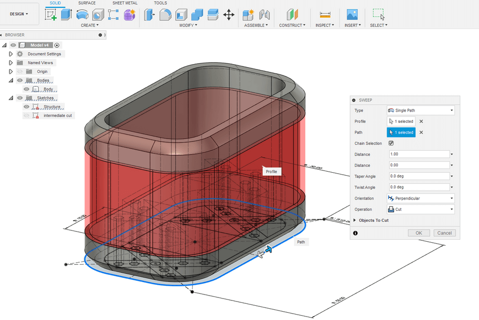
This tool is very useful for cutting curve geometries, this is the result I achieved! I also did a fillet to the upper frame in order to waste less material.
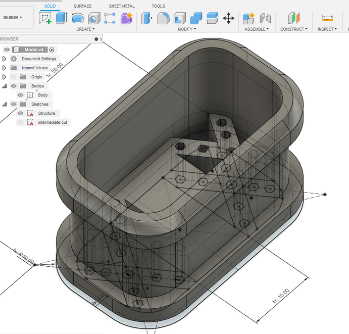
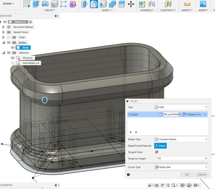
I thought that doing the fillet of the all corners was a good idea so I did it
Once done all aestethic job, I checked if the parametrization of the thickness was working correctly and it worked well!
Then i needed to create some holes for helping the cable holding and organization , so I started projecting geometries in order to mantain the right link of the lines even if the parameters will change:
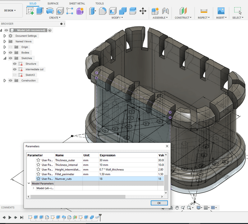
Then I wanted to accomplish a pattern on a curve path, since I never used this tool I was also a little confused about used it. I was searching for a method of obatining a parametric number of equally spaced cuts. I found something HERE, it’s only a rough guideline, but it helped me a lot.
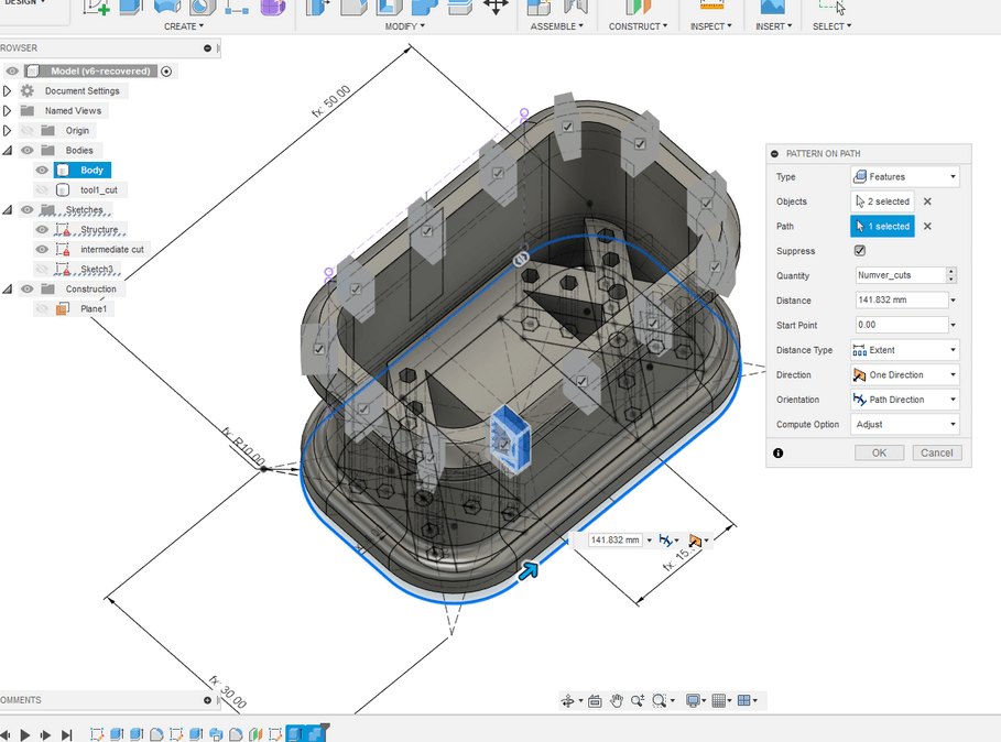
The important thing to notice here is that if you are changing the parameters , you have to re-configure the pattern on path, since the distance is changed because of parametric change. In order to acccomplish that you need only to let the start point coincide with himself after one turn.
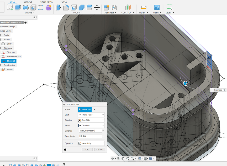
Then I noticed that the extrusion of the upper cut wasn’t right, there were some leftover so I doubles the extrusion distance
Then I tried to increase the number of cuts, and it worked! But since id didn’t do the “distance” field modification, the cuts are not equally spaced.
At the end I checked the height parameters if it was still working:
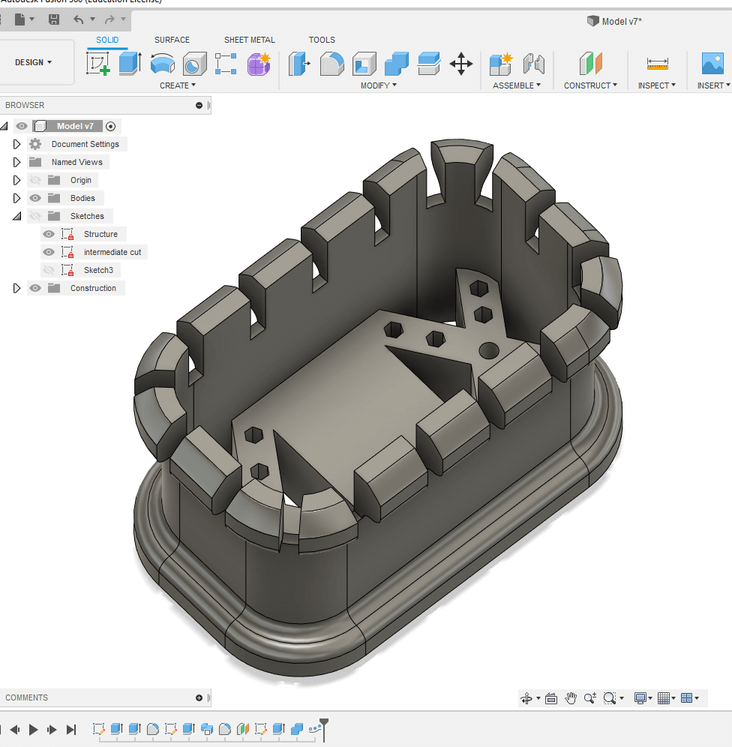
Here’s an Overview of the final design:
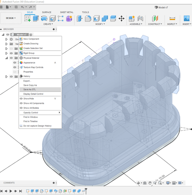
Exporting as STL
Saving the model as stl file it’s a piece of cake! Just right click on the model’s menù to find this function: