Computer Controlled Cutting
Federico, 12 February 2020
The assignments of this first week were:
- group assignment: characterize your lasercutter’s focus, power, speed, rate, kerf, and joint clearance
- individual assignment: cut something on the vinylcutter design, lasercut, and document a parametric construction kit, accounting for the lasercutter kerf, which can be assembled in multiple ways, and for extra credit include elements that aren’t flat
Link to the lesson. Link to the videolesson.
Inkscape self learning session
Laser cutter Design
I followed this guide to start learning from a simple design example.
The tricks I’ve learned are:
1) To design 3d laser cutter things is better to start with fusion and to divide everything you add in single component. This is really useful and time convinient if you have equal multiple bodies.
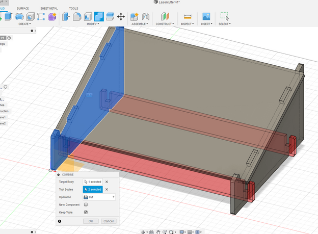
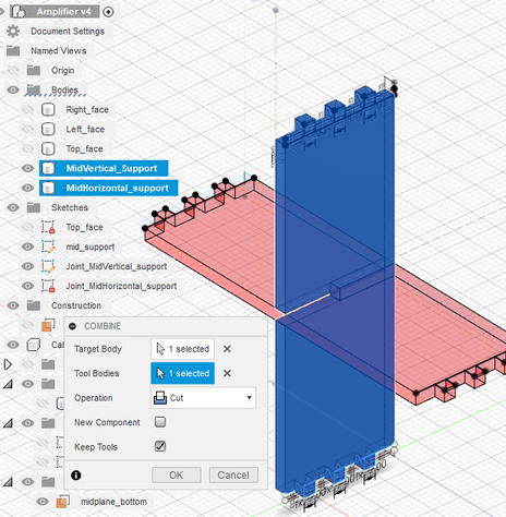
2) The “ Combine” function is really useful to let one bodies cut the other. This is intended to speed up the process making interlocking joints. You have to select the target body ( the one that will be 3d- cutted) and the Tool body (the body that will cut the target body). Alway remember to check “ Keep Tools” if your tool body take apart of your 3d design
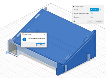
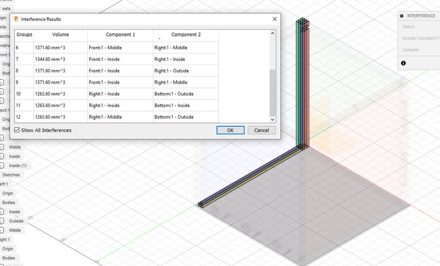
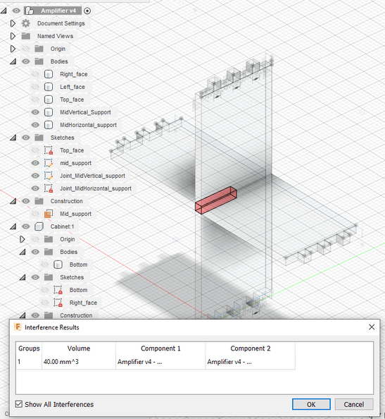
3) At the end of your design is very smart to check everytime with the interferences with the Inspection tool: Select the everybody and click to “Calculate” to compute all 3d-common bodies to find errors very quickly.
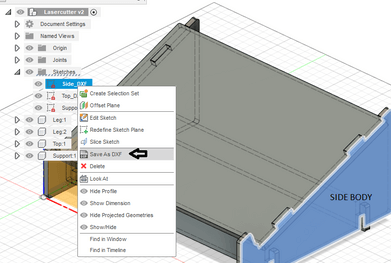
4) Saving in DXF for laser cutting is very easy. start a new sketches (and immediately finish/stop it) for every body/surface you want to lasercut. Then in you “Sketches” drop down menù you can export them by click on “ Saving DXF”.
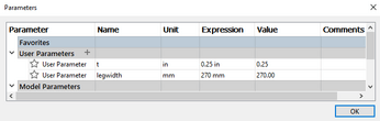
5) Always use “User Parameter” tab in the path “ Modify > Change Parameters”. This will let you expoit the parametric design approach at its best. In this way you can easily change some distances, offset and others when the design is almost finished. So you don’t have to redesign everything if you need to change something. Fusion 360 will also let you give access to the history bar to change things you’ve done in the past, But I found the “ User parameter way” more quick.
Then I followed also this tutorial to master the concepts,here’s are some key concepts:
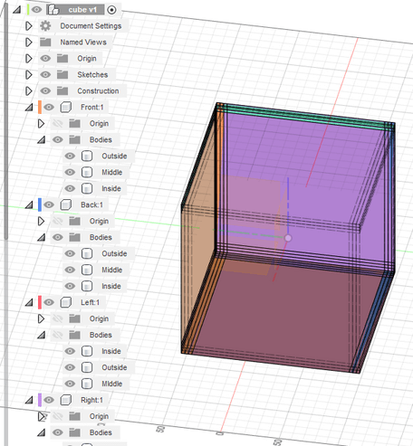
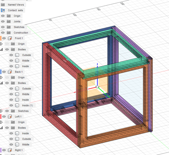
6)Always remember to exploit some design symmetries. In this example is really convienient to copy and set the user parameter referred to a pivot point the cube center. This is really useful for scaling and use the full force of parametric design if you want to change things. Organizing the design in more subcategories is needed to don’t fall in confusion if you have a lot of bodies in your project. In this case is preferred to sub-divide parts in 3 categories. It’s also very good to use the color splitting tool (Component color Cycling Toggle) with the shurtcut “Shift+N” to better visualize very similar pieces.
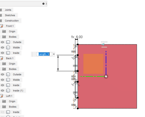
7)The best way to design good joints is to dimension good parametric overhang: always try to refer them to the main parameters!
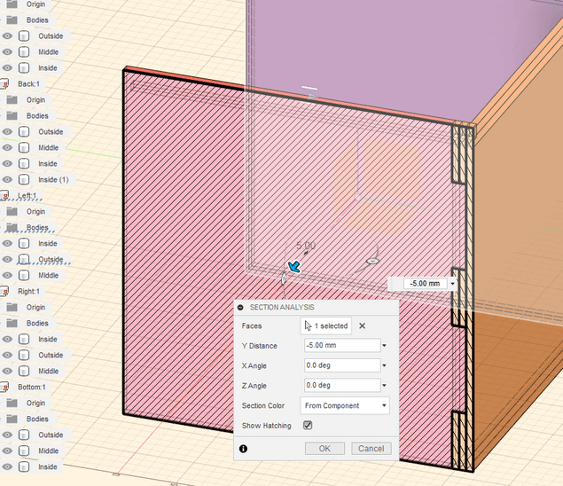
8)While your work is in progress, it’s a good rule of a thumb to check your project by section analisys. This let you check if something is going wrong moving towars all sections fo you design.
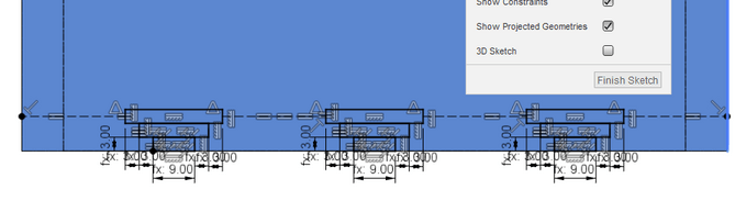
9) When creating dovetail multilayer joints, remember to refer all the measures to the thickness of your material:
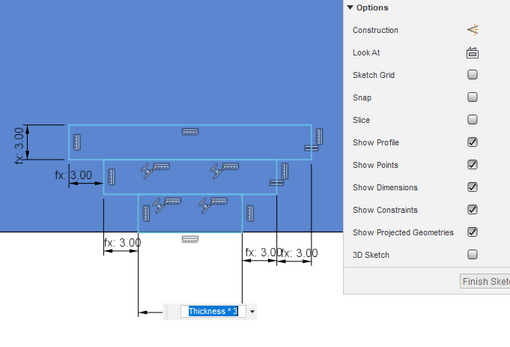
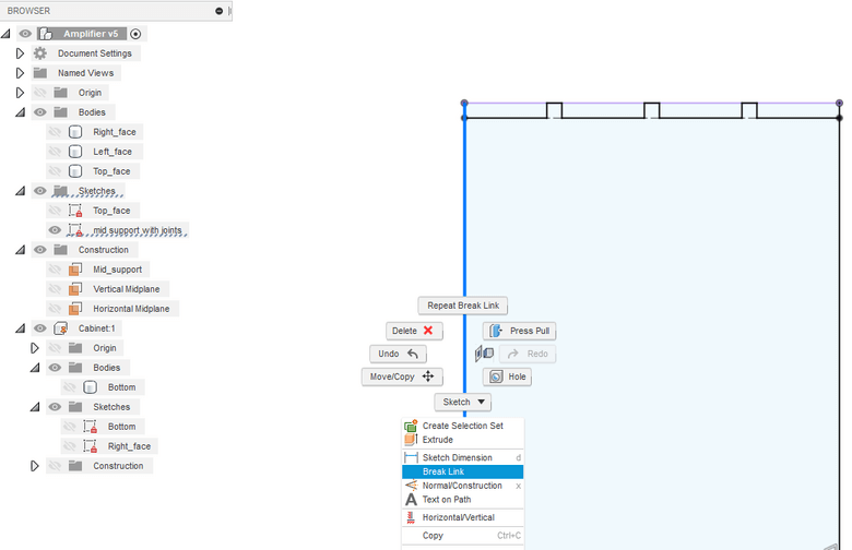
10) One cool trick to equally separate the joints is to draw a construction line between them and to apply the “equal constraints” between all of them.
11) Use the Interference tool to know where are the missing area that needs some adjustement:
12) Here we can see the advantage of using the history bar of Fusion 360. We can change the initial square sketch (then we know all pieces are copies of the first sketch) to change the entire design in few steps:
Laser cutter project: mini guitar amplifier cabinet
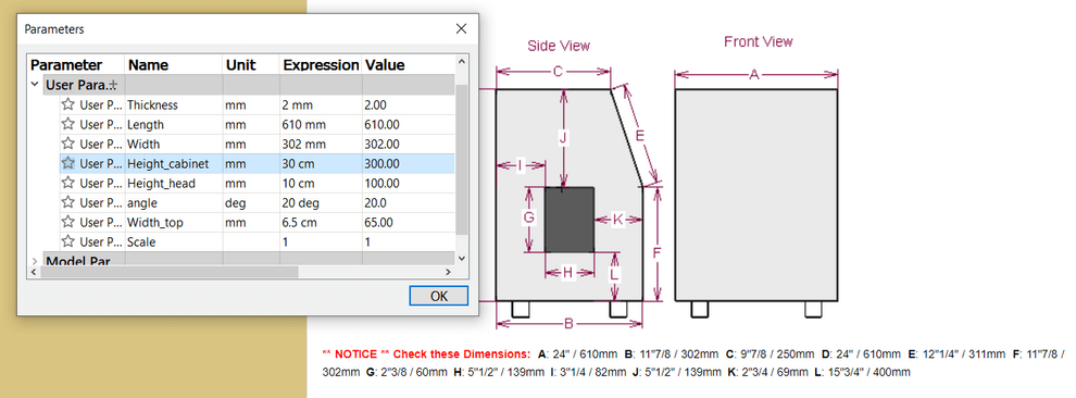
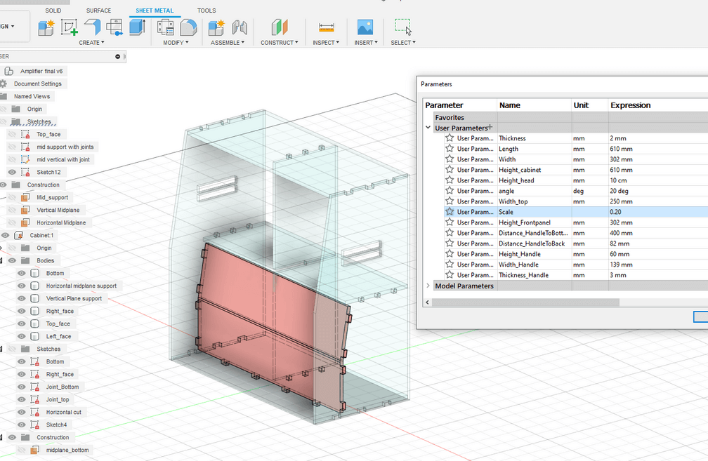
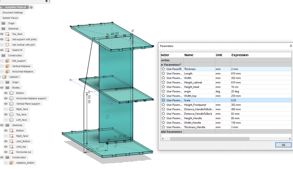
First of all I decided to fetch the measure of a real amplifier from the web. I got an aproximate value of all measure from the sites of a company that produces cabinet’s covers. Then I created the user parameters for the essentials measure in order to keep the project fully parametric. I think this will be essential since I don’t have access to the lab now so I won’t know if there will be any need of change one of these parameters (e.g. the stock thickness can be different ). I decided also to enter the parameters SCALE for a very quick resizing and this will be used for every sketch, extrusion, dimensioning that needs to be resized, be careful of that).
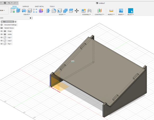
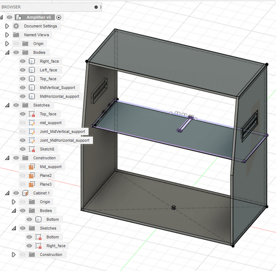
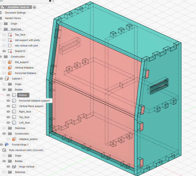
Then I started creating the skeleton of the cabinet. I started by integrating the user parameters I defined before and tried to center the origin of the design within the origin of the cabinet. In this way everything would be more simple if I have to mirror parts.
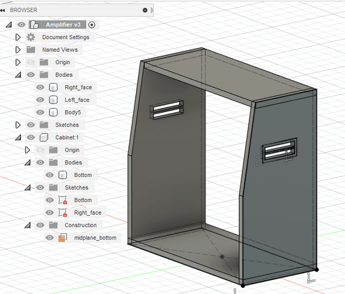
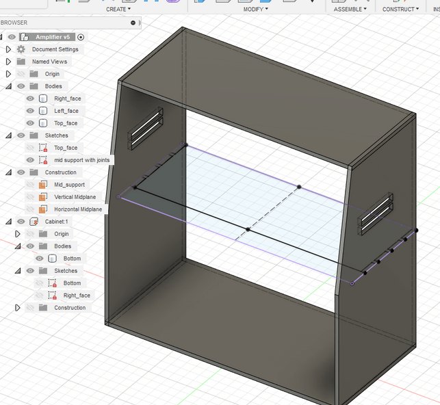
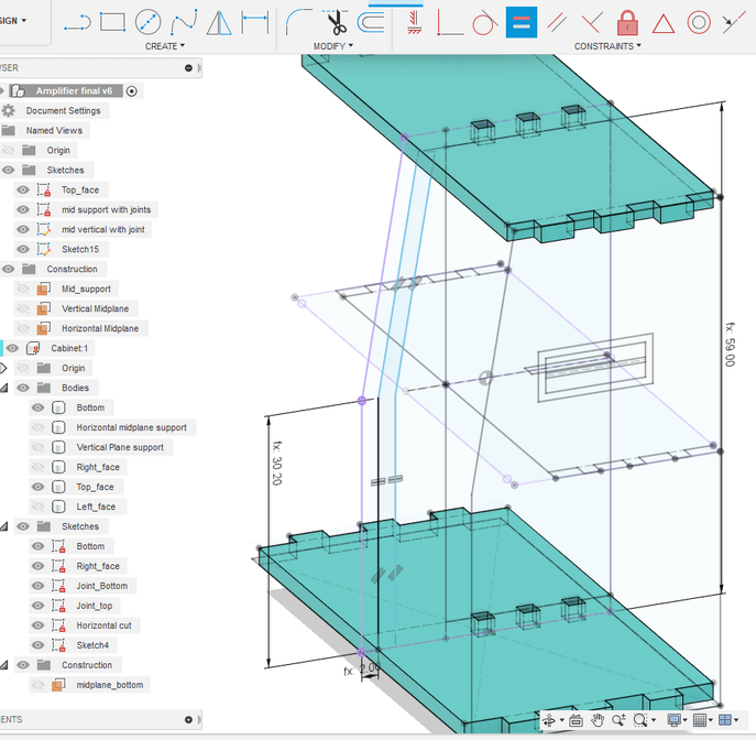
I decided to create some midplanes from the top and the bottom faces of the design ( and same for the right and left part) so I’ll be sure that if I’ll sketch here, the middle support will have 4 equal squares ( it would be good to place some drawers and to open them from the back. I like the idea of hidden drawers so much ). Then I used the Joint command to define the distance betweend the right and left sided.
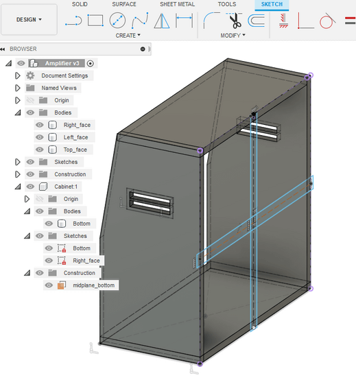
I extruded the cross from the back towards the front of a distance that’s 80% the lenght of the midtop so I entered the full expression as parameter of extrusion.
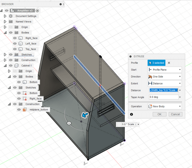
After a simmetrical extrusion for the middle supports, I decided to sketch a simple 3-fingered joint in order to let the entire structure be more stable. Even if this could be trivial, be careful the width of the finger has to be equal to the Thickness. Then I choosed one the the supports and started to draw a sketch for a cut. This has to be done to guarantee a strong joint between them. In order to do cut the remaining body, I used the combine tool to use the first body ad a cut tool ( remember to check the box “keep tools” or the body tool - the red one - will disappear).
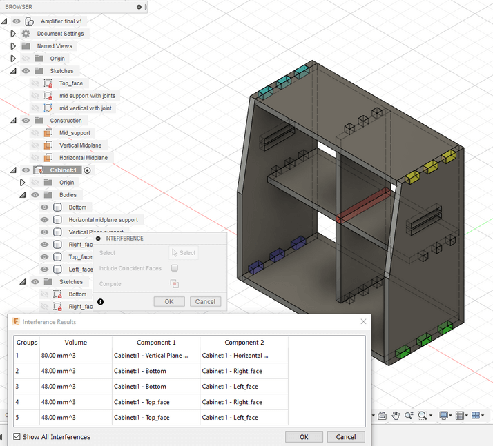
In order to don’t forget which many other tool still have many parts in common I used the Interference tool in order to keep track of them.
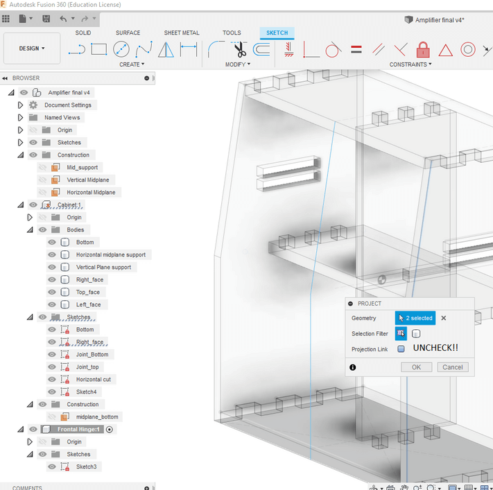
Be careful of projecting sketch of well defined geometries
I think is better to sketch over a midplane than to project other geometries’ sketch on the midplane. This is because I encountered some problems in obtaining the results I was expeting while changing the SCALE parameter. You can see that problem if changing the use parameters something is disappearing.
This happens everytime you project a sketch. This operation will take some constraints referred to what did you project. At this point I deleted the midsupports to restart a clean drawing of them. In order to break the costraints of a projected sketch, you need to break link while you’re projecting or after, with a right click on the interested projected sketch.
I wanted to save some useful time, so I decided to mirror the lines from one side to anothe with the aid of a middle construction line.
Then I cut some other finger joint for the case and run the interference tool in order to know whick body I had to set as a tool and those as target.
Then I started to make the frontal cover. To do so, I projected the side geometrie over a Vertical midplane. Then I extruded it simmetrically with outgoing direction to that plane. I wanted the lenght to reach the external plane of the side panel of the cabinet so I can cut-extrude some finger in order to keep it stationary.
then I decided to cut the finger joints and combine them to the cabinet.
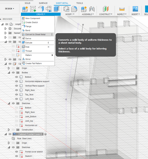
Then I tried to convert the frontal cover to a sheet metal but BE CAREFUL, here’s the problem:
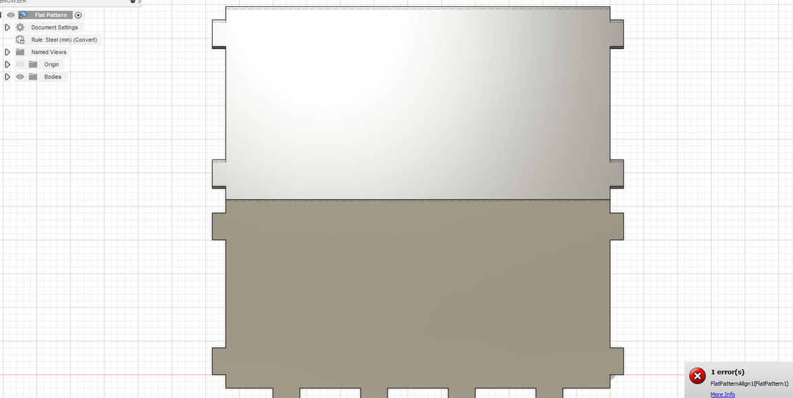
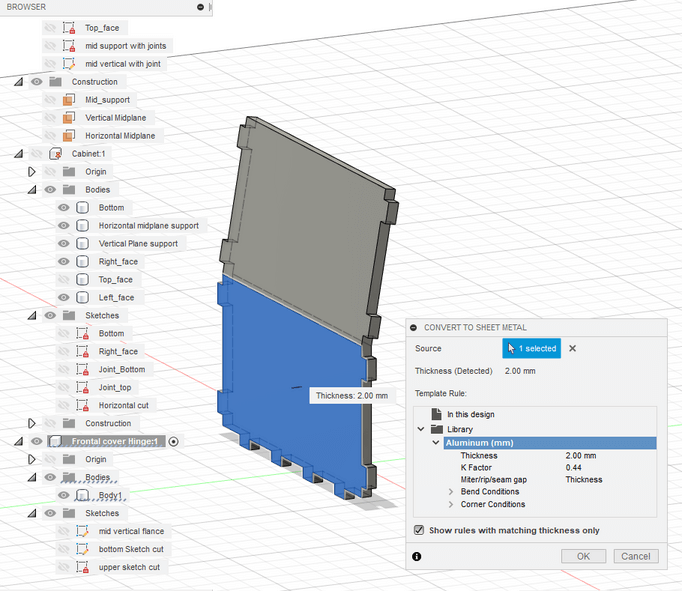
Since this extrusion is based on a projected sketch, this sheet metal is fixed so it can’t FOLD/UNFOLD/MOVE from there. After a lot of struggling I decided to sketch on the same midplane but unchecking the projection’s link box.
Once done this, Fusion let me convert the frontal cover in a sheet metal, so everything should be perfect…
while instead, I tried to change the SCALE parameter, at this point:
Instead of being hopeless, I tried to sketch with accuracy in the midplane one more time, but refererring everything to the origin.
Then I decided to directly create a FLANGE from metal sheet tools and it worked fine! Now I can see line of folding on the cover, this is a good sign.