Output devices 📋
🕘 Date / Time:
Hello there..^^. Hope a large smile finds its way to your face inspite off all the panic that COVID-19 pendemic is causing <3 ^^. Let's hope everything will be fine now that we're on the 9th week of Fab Academy.. ^^
____________________________
A) Group Assignment:
Measure the power consumption of an output device.
Document your work (in a group or individually).
____________________________
B) Individual Assignment:
Add an output device to a microcontroller board you've designed and program it to do something.
Output circuit function:
For this week I designed an output circuit that functions as follows:
The circuit basically sweeps a servo motor by changing from an angle to another in a particular speed, with an LED being lit while the motor is moving.
Output circuit desgin:
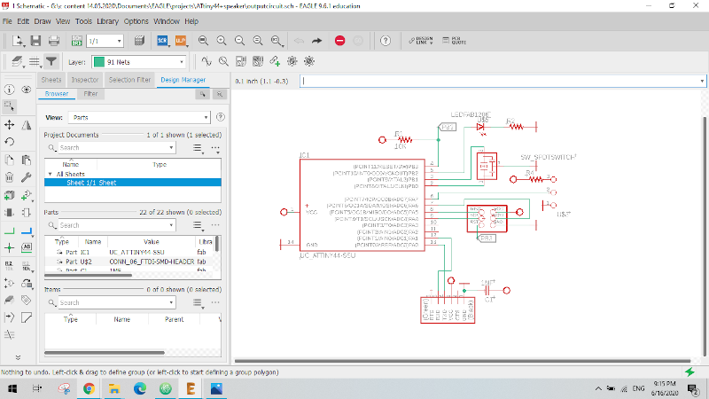
I. Schematic diagram:
I started my design based on hello echo board so, less time was consumed designing this circuit as I'm strating to get more & more comfortable and much more familiar with electronics design tools and the process of routing.
And here you can see the schematic diagram of my output circuit.
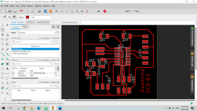
II. PCB design & routing:
Organising the PCB was relatively easy this time except for the wire crossing issue I told you about that led me to use an zero ohm resistor as a jumper wire after _honestly_ a considerable time spent in failed trials.
Here comes Awesome PCB no.03 ..^^


Output circuit Coding:
      int servoPin = 7;
      int LED= 8;
      int myAngle;
      int pulseWidth;

      void setup ()
      {
        pinMode(LED, OUTPUT);
        pinMode(servoPin, OUTPUT);
      }

      void servoPulse(int servoPin, int myAngle)
      {
        pulseWidth = (myAngle * 10) + 600;
        digitalWrite(servoPin, HIGH);
        digitalWrite(LED, HIGH);
        delayMicroseconds(pulseWidth);
        digitalWrite(servoPin, LOW);
        digitalWrite(LED, LOW);

      }

      void loop()

      {
        for (myAngle=50; myAngle<=120; myAngle++)

        {
          servoPulse(servoPin, myAngle);
          delay(20);
        }
        for (myAngle=120; myAngle>=50; myAngle--)

        {
          servoPulse(servoPin, myAngle);
          delay(20);
        }
      }
Output circuit manufacturing :
Unfortunately, I forgot to take a photo of the milled PCB before soldering the components. 😅
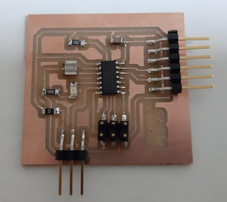
Aparently it wouldn't be me if all went well without any problems or stupid mistakes.😁😁
The really strange mistke this time was that I somehow designed the circuit as if servo pins order is (Ground , Signal, +5V) and all terminals of servo motors on earth are known to be (Ground , +5V , Signal). 🤦♀️🤦♀️
I really don't know or remember why or how I did this annoying mistake ><. But thank Allah it was something that could be overcame with the help of 3 female-male jumper wires.😌😄
Functioning output circuit:
Downloadables: 💾
Arduino File.inoHere
Eagle CAD Files .sch & .brdHere
Note: I fixed the order of the servo pins in the eagle files provided. ^^
___________________________________________
©️ Row'a M. M. Othman - Fab Academy 2020