Input devices 📋
🕘 Date / Time:
Hello there..^^. Hope a large smile finds its way to your face inspite off all the panic that COVID-19 pendemic is causing <3 ^^. Let's hope everything will be fine now that we're on the 9th week of Fab Academy.. ^^
____________________________
A) Group Assignment:
" Probe an input device's analog levels and digital signals". That was what we are required to do as a group for this week which we couldn't do as the tea is not allowed to gather in the lab due to social distancing calls.. :(
____________________________
B) Individual Assignment:
Measure something: add a sensor to a microcontroller board that you have designed and read it.
Input circuit function:
For this week I designed a dual perpose circuit using an LED, slider swtich and LDR (Light dependant Resistor) AKA photo resistor or light sensor as an example of analog input & pulse width modulation.
The circuit functions as follows:
1- When the slider switch is on:
The LDR senses ambient light intensity. The LED acts as adaptive lighting for the perpose of keeping the room lit as the sun sets.
2- When the slider switch is off:
The LDR senses ambient light intensity. The LED acts as auto brightness _Just like smart phones screens_for the perpose of providing visible screen content in high levels of ambient lighting.
Input circuit desgin:
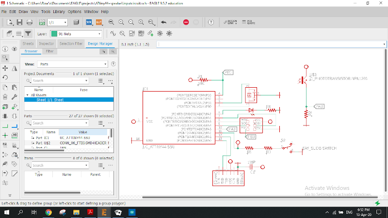
I. Schematic diagram:
I started my design based on hello echo board so, less time was consumed designing this circuit as I'm strating to get comfortable and much more familiar with electronics design tools and the process of routing.
And here you can see the schematic diagram of my input circuit.
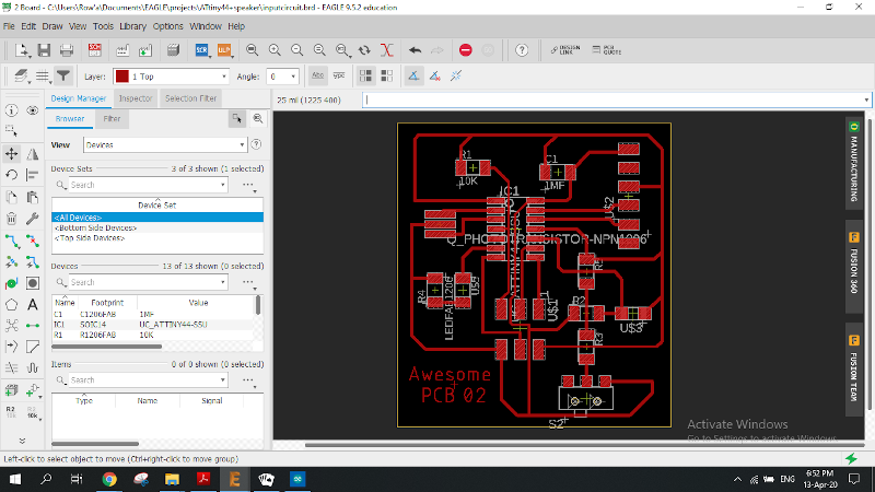
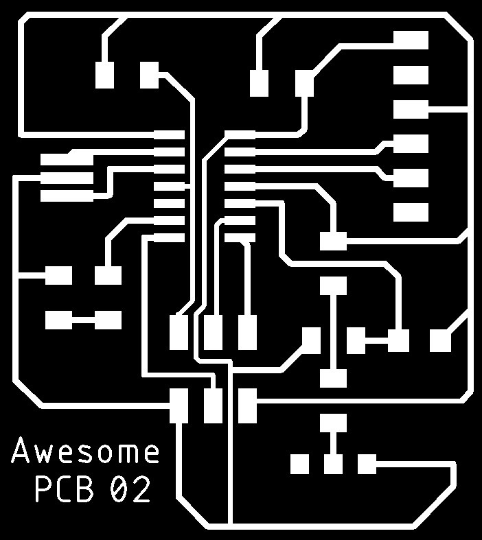
II. PCB design & routing:
Organising the PCB was relatively easy this time except for the wire crossing issue I told you about that led me to use an zero ohm resistor as a jumper wire after _honestly_ a considerable time spent in failed trials.
Here comes Awesome PCB no.02 ..^^

A question, some research then an answer:
It was just then that I coincidentally noticed that Fab inventory does not contain a (photoResistor) / (LDR) instead it has (photoTransistor) which I've never used..!!
Doing some research and consulting my instructors I was relieved to find out they did the same function but horrified as they may not connect to the circuit the same.
I initially thought my connection did not have a problem but was told that the output signal of a phototransistor along with the resistor had to be connected to the VCC side.
So, I had to do some research on this matter as I was kindda perplexed.
1- Here I learnt that my initial connection is called Common collector , and the other one is called Common emitter and that both connections are valid but quoting them "The choice of common emitter or common collector phototransistor circuit configuration depends upon the requirements for the circuit. The two phototransistor circuit configurations have slightly different operating characteristics and these may determine the circuit used."
2-HereI found a really useful comparison between photodiode, phototransistor and photoresistor. (He connected the phototransistor the way I did).
3- And finally thereI landed on the comparison between the two connections.
Conclusion:
For the phototransistor to act the way I wanted the assembly wouldn't really matter as long as I adjust the code for the mode I would like the circuit to start with (Even thought it also wouldn't matter as I'm using a slider switch not a push button in the real circuit).
So I chose to leave my design circuit Common Collector as it already was. ^^
Input circuit Coding:
const int LED = 7;
const int PhR = 3;
const int Slider = 2;
int lightLevel;

void setup()
{
  pinMode(LED, OUTPUT);
  pinMode(PhR, INPUT);
  pinMode(Slider, INPUT);
}

void loop()
{
  if (digitalRead(Slider) == HIGH )
  {
    lightLevel = analogRead(PhR);
    lightLevel = constrain(lightLevel, 0, 900);
    lightLevel = map(lightLevel, 0, 900, 0, 225);
    analogWrite(LED, lightLevel);
  }

     else

     {
    lightLevel = analogRead(PhR);
    lightLevel = constrain(lightLevel, 0, 900);
    lightLevel = map(lightLevel, 900, 0, 0, 225);
    analogWrite(LED, lightLevel);
      }
 }

}
Arduino Circuit:
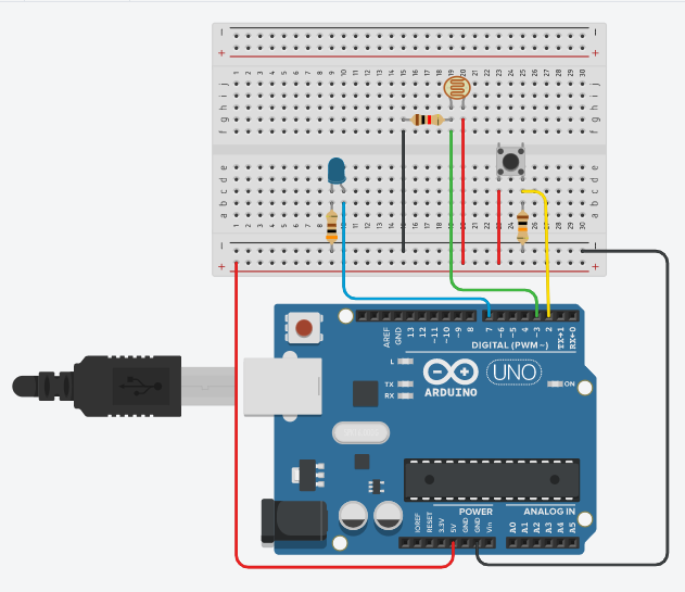
Arduino Simulation:
When the button is pushed it acts as auto brightness.
Input circuit manufacturing:
Note:
Unfortunately, milling and what follows have been done after about two months due to lockdown.
That's why I had to use an Arduino circuit and Tinker CAD for simulation & implementation first. And that was also why I didn't have the time to mill another PCB after this one almost broke. Instead I had to be okay with fixing the ruined trace with soldering tin and overlooking the very bad looks of it.


After milling, soldering and programming my lovely input board AKA "Awesome PCB 2" :D, I was shocked to have done a really stupid mistake. It was that the slider switch is connected in a WRONG way and it can never switch between the two different states my circuit was intended to have. 😔😔
Even though it was so easy to correct my design to have the switch work properly, I didn't have time to re-mill another circuit, so I had to accept this one with half the function. It is an input circuit after all. 😕
Functioning input circuit:
Test the other function I reprogrammed the circuit with the second half of the code and it worked. 😁💃💃
Downloadables: 💾
___________________________________________
©️ Row'a M. M. Othman - Fab Academy 2020