Electronics Production 📋
🕘 Date / Time:
Aloha there..^^ , hope everything is going great ^^. This is our forth week of Fab Academy and things are getting much more exciting!
We had a group assignment and Individual assignment just like last week. ^^
A) Group Assignment:
The Assignment was documented on the lab page.
My Reflections:
Saturday afternoon we started discussing how we’d approach the group assignment. It seemed such a simple task at first, except that it wasn't.:D
I wasn't at all familiar with the process of milling a PCB, so it was observing time. :D
I observed my colleges upload the test .png file to Fab modules, with few clicks we've had our .rld file, the file then was to be saved to the computer, to be uploaded to "V Pannel" the "Roland MDX-40A" milling machine software.
I learnt about different types of end mills and the finishing each one gave us as well as the horific finishing we get when the end mill is broken.
I learnt how to:
1- Make sure the machine is clean and the workbed
2- Install and change the end mill if broken.
3- Install a leveled sacrificial layer.
4- Methods and precautions to operate the machine.
5- Set the zeros.
6- Use the z axis sensor.
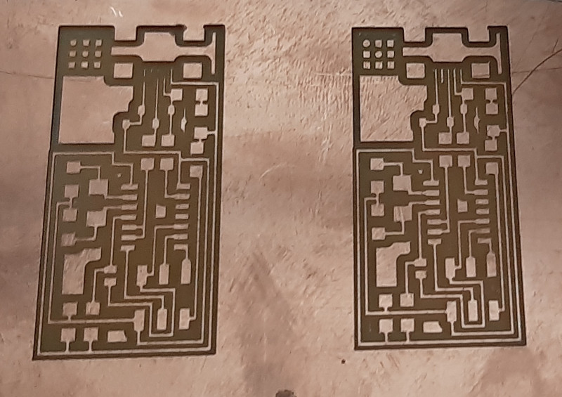
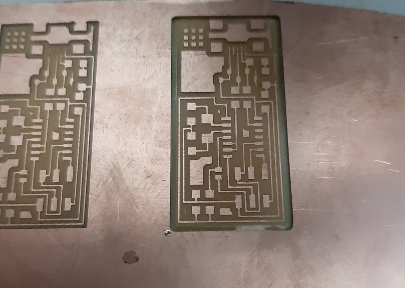
The test was required to determine how clean the output spaces and traces are going to be using different end mills.
Trying to get to a good finishing for several hours we then came to the conclusions that:
The FR 01 copper sheets we're using are of a low quality.
The "SRM-20" milling machine gave better results than "Roland MDX-40A" regarding cleanliness and quality of milling (We Supposed that this was because fab modules has the machine model MDX-40 not MDX-40A )
B) Individual Assignment:
Steps:
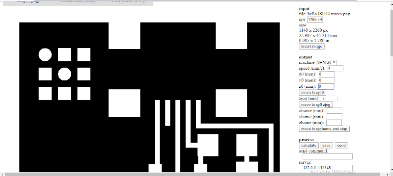
A) Fab Modules:
1- Click input format > select (Image.png) > choose your file.
2- Click output format > select (Roland mill (.rml)).
3- Click process > For traces choose (PCB traces 1/64) - For outline choose (PCB outline 1/23).
4- On your right choose the machine (SRM 20 in my case).
5- X0 = 0, Y0 = 0, Z0 = 0.
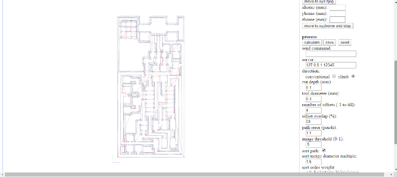
6- Click calculate then wait a little bit.
7- When it's done calculating, click save to download your .rml file.

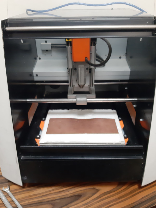
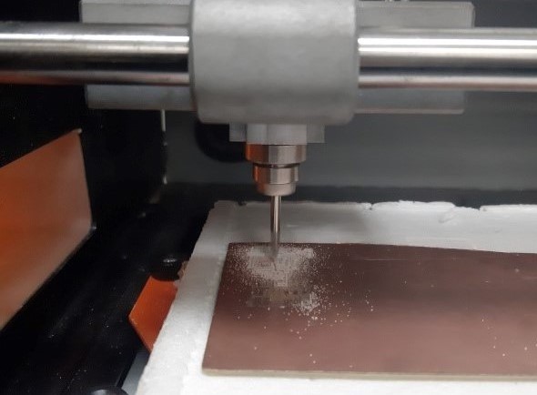
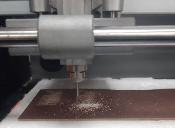
B) Machining:
I. Hardware:
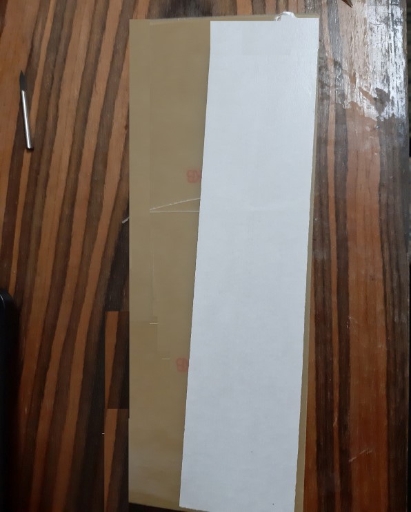
1- Prepare a suitable size FR01 sheet.
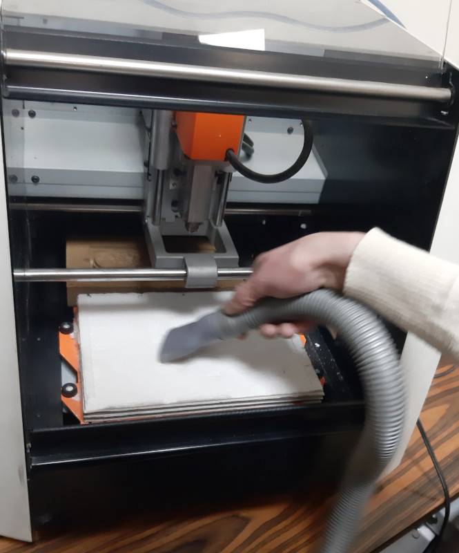
2- Vacuum clean the machine to make sure these's no dust.
3- Prepare a smooth and well leveled sacrificial layer (MDF in our case) and stick it well to the machine work bed using double tape. Make sure neither to leave any air bubbles under the tape nor overlap two stripes.
4- Apply multiple stripes of double tape to the FR 01 sheet and keep them from wrinkling or overlapping.
5- Fix the FR 01 sheet airtight to the MDF to ensure it's at a fixed level relative to the endmill.
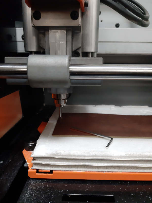
6- Install the endmill very carefully.
7- Make sure machine door is closed.
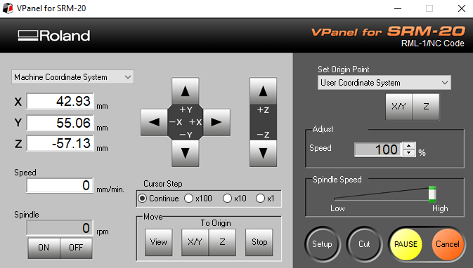
II. Software:
1- Make sure SRM-20 V pannel and the machine driver are installed on your laptop.
2- Connect your laptop to the machine.
2- Set machine axes to the zero position.
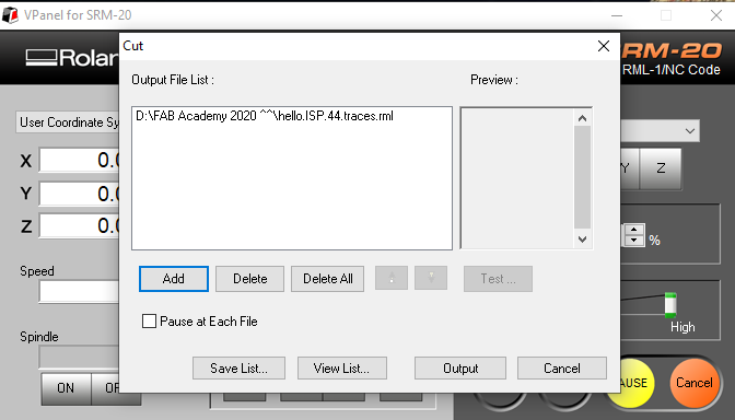
3- Click cut > add > add your .rml file > click output.
4- Let the machine do the work.
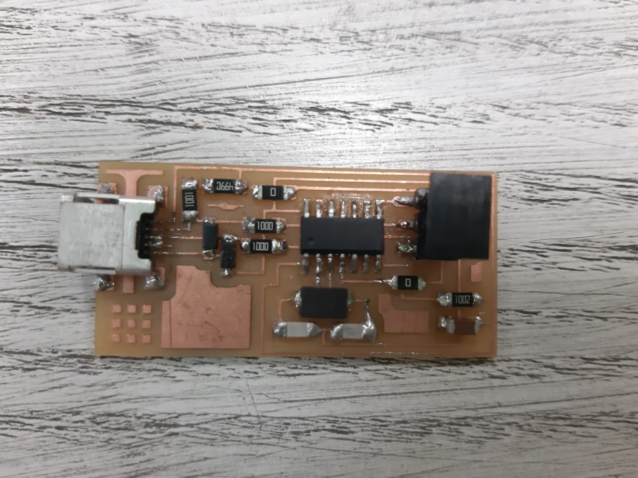
C) Soldering Surface Mount Devices:
The moment I'd learnt that we're going to have to solder SMDs I got really excited. And I'd betted myself that I would enjoy it and it wouldn't be trouble.
Getting to the moment of truth I did in fact enjoy it a great deal but it wasn't as easy. As soldering these really tiny componenets on a really small PCB not to mention positioning them in the first place can be quite a challenge. :D
Note:
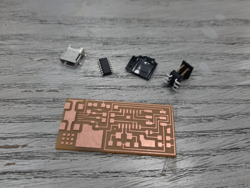
- The ATtiny, crystal, USB port and pin headers were the only available SMDs in the Lab that moment, Other components were yet to arrive.
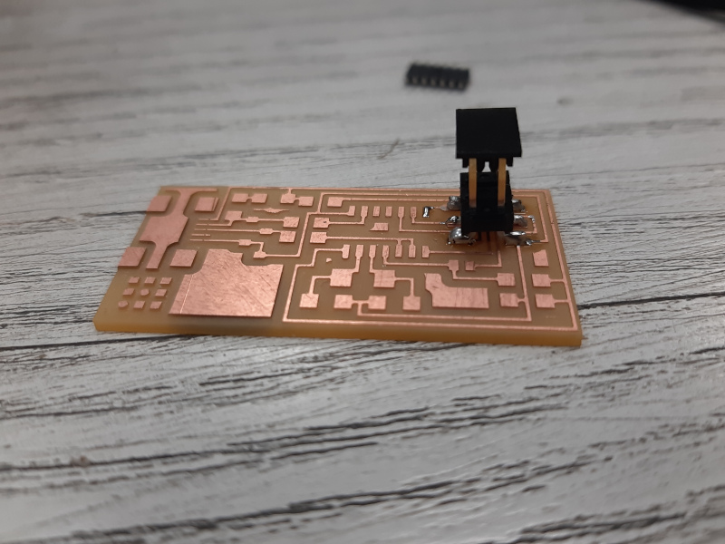
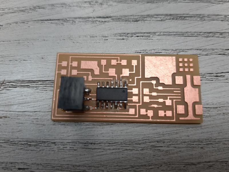
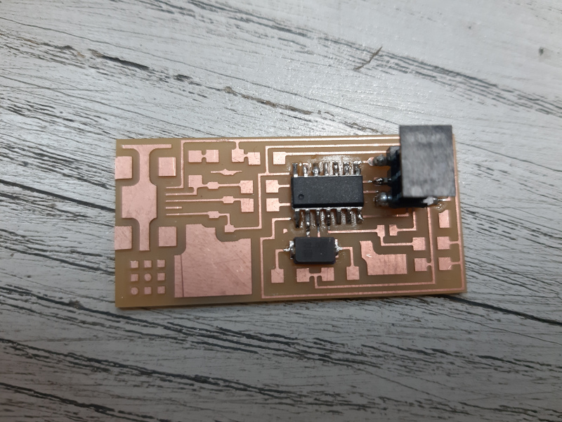
Below you can find the photo documentation of the soldering steps:
Failures:
1- Tried to set the zeros / upload the .rml file to V Pannel while the machine door was up.
2- Uploaded the outline file and forgot to acount for the machine zeros of the traces.
D) FabISP Programming:
Here we came to ISP Programming, which was the most intimidating part for me.
I feared even starting it because of the whole load of all different complicated tutorials I found. Till I came across this great tutorial (God bless its author) that had almost all the details needed for the mission.
This part is devided into two parts:
I) Burning the bootloader on the ATtiny.
II) Getting the computer to communicate with the board. AKA PC related steps :D.
I. Burning the bootloader on the ATtiny 44:
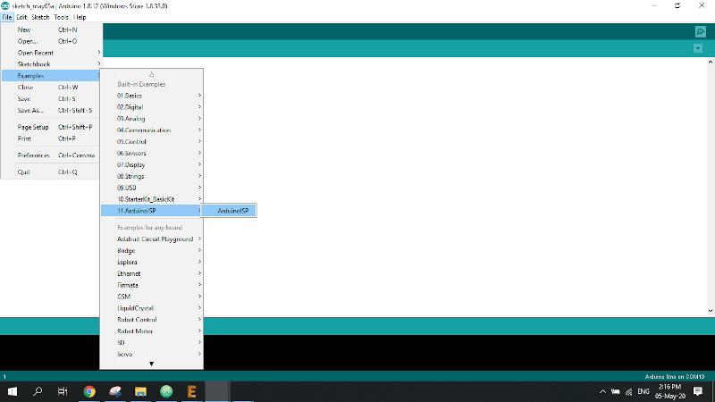
Fisrt step: Preparing the Uno to be the programmer.
1- Get yourself an Arduino Uno Board that we're gonna use as a programmer.
2- Connect the Uno board to the computer and open Arduuino IDE.
3- File >> Examples >> 11.Arduino ISP. >> Arduino ISP.
4- Make sure that the settings are correct:
- Tools >> boards >> Arduino Uno.
- Tools >> Port >> " The common port to which the Arduino board is connected".
5- Upload that example to your programmer Arduino board.
The process is successful when it writes "Done uploading."

Second step: Wiring.
1- Connect the ICSP headers of your Uno programmer to the corresponding pins on your ISP board.
💡 Except for the ISP "Reset" pin, you're gonna have to connect it to Digital pin of the Uno.
2- Connect a 10µF electrolytic capacitor to the Uno's RESET and GND with the positive (long leg) connected to RESET.
💡 The capacitor has to be placed after the programmer board has been loaded with the ISP sketch. (1st step)
Wiring is done & we are good to go. ^^
Third step: Burning the bootloader on the ATtiny 44.
1-You're gonna have to install the ATtiny support in your Arduino IDE.
- File menu >> Preferences >> “Additional Boards Manager URLs” field near the bottom of the dialog box.
- paste the following URL, then click "ok"
"https://raw.githubusercontent.com/damellis/attiny/ide-1.6.x-boards-manager/package_damellis_attiny_index.json"
- Tools >> Boards >> Board Manager >> Scroll down till you find an entry for “ATtiny”.
- Click on the ATtiny entry. An install button should appear. Click the install button. The word “installed” should now appear next to the title of the ATtiny entry.
- Close the boards manager. You should now see an entry for ATtiny in the “Tools > Board” menu.
2- File >> New.
3- Tools >> Boards >> ATtiny 24/44/84.
4- Tools >> Processor >> ATtiny 44.
5- Tools >> Clock >> External 20 MHz.
6- And Finally .. Tools >> Burn bootloader.👏
Having reached this step congratulate and applaud yourself 👏, you're half way to a functioning ISP Programmer.💪👏
II. PC related steps:
In order for the PC to contact the ISP board we're gonna have to install some softwares (AVR Dude, Adafruit Drivers & FabISP Firmware) and follow some steps.
First Software: AVR Dude.⚠️
Because this software is obsolete, installing it right away may cause great damage to your computer. To prevent damage, you should do something called: " Backup your path environment" by which you reserve your PC data from being altered.
To do this (reserve your data) you're gonna have to follow those steps thoroughly:
1- Start "Windows Registry Editor" (Win key + regedit).
2- Navigate to this folder [ HKEY_LOCAL_MACHINE\SYSTEM\CurrentControlSet\Control\Session Manager\Environment].
3- Right click on "Path" to modify it, select it all (ctrl+A) then copy it to any document file eg:(Notepad)
4- Save your document or make sure its content is reserved, then & then only it's safe for you to install AVRDude.
5- Install AVRdide following the regular steps of installation.
6- Reopen regedit, navigate to the same location & compare the copied path in your notepad to the current path.
- a- If the WinAVR folders were added to the previous path, >> Do nothing. You are safe.
- b- If the paths you copied were missing, >> add them back after the WinAVR path separating enteries by a semicolon. You saved your PC and now you're off the hook.
In my case, the new path was added to the old ones. Despite of all my panic, ironically I was safe.^^
Second Software: Adafruit Drivers installer.
Download and install the drivers on your computer. No special precautions, just download & install.
Effect of this step won't appear till we're done with all the remaining steps & connecting the ready ISP directly to the PC.
Third: Fab ISP Firware.
We're getting closer and closer to our goal. The job is almost done!
This step is not a program to be installed, instead it's a zipped folder to be downloaded.
1- Download fabISP_08.2_firmware.zip.
2- Extract the folder & move it to your desktop.(for me that was easier to reach using the cmd window.)
3- Find a file called "Makefile" & open it with any text editor you choose eg. notepad.
4- Replace the
AVRDUDE = avrdude -c avrisp2 -P usb -p $(DEVICE) # edit this line for your programmer
with this line
AVRDUDE = avrdude -c stk500v1 -b19200 -P COM3 -p $(DEVICE)
💡 Just keep in mind that you'll have to edit "COM3" so that it matches the number of the COM port you're connecting the Uno to.
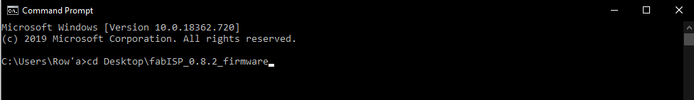
5- After saving the makefile close it then get to start menu and write cmd / command prompt.
4- Having the cmd prompt open you're gonna have to write down those commands in order.
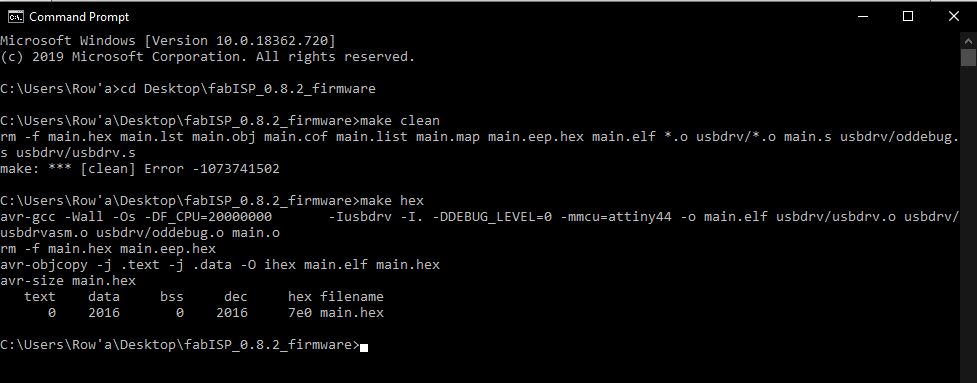
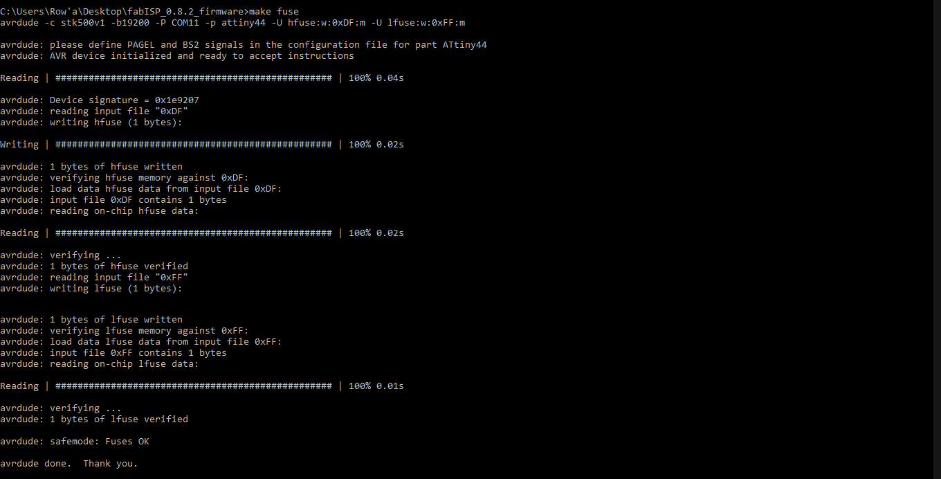
💡 The resutls of each step that shows it was successful is shown in the images of the command prompt.
cd Desktop\fabISP_08.2_firmware
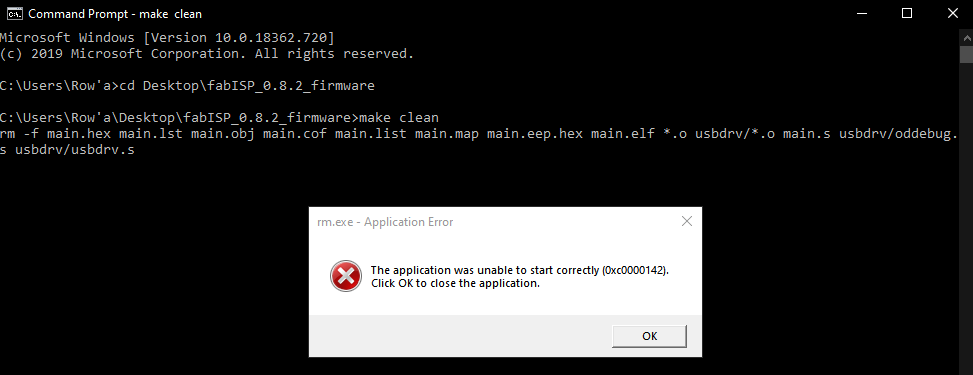
make clean
The tutorial I followed stated that: "If you get an error when you type "make clean" just proceed with the next command." That was what happend with me, I did proceed & the following steps worked. ^^
make hex
make fuse
make program
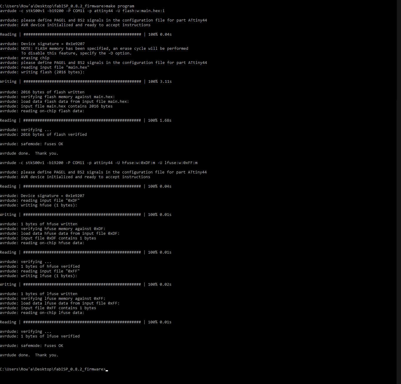
Having done all the Steps, Say Horraaaaaaaay!! 'cause now you've got a functionning ISP board!
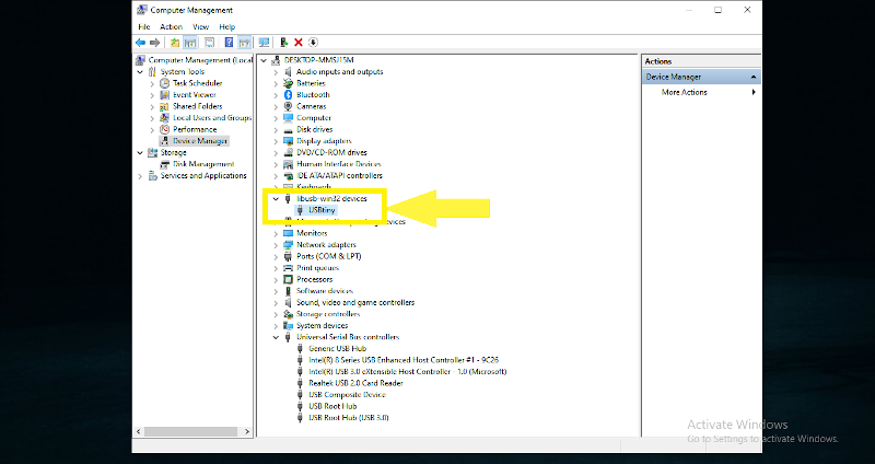
To make sure your programmer is working correctly(make sure the ISP is connected to your computer), check device manager. You're gonna find "USBtiny"
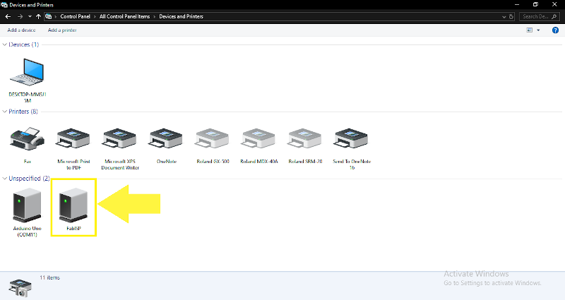
For further confirmation got to Control Pannel >> Devices and printers. And you're gonna find FabISP.
©️ Row'a M. M. Othman - Fab Academy 2020