Aloha there..^^ , hope everything is going fine ^^. This is our seventh week of Fab Academy and the world is panicing about the COVID-19 aka "Corona Virus". Here in Egypt we've been going through weather problems of our own, in addition to that Corona thing due to which schools got closed, gatherings got banned and most people were ordered to stay home.
We had a group assignment and an individual assignment just like every week. ^^
A) Group Assignment:
The group assignment was to characterize the CNC machine we have in our lab. There is something wrong with the machine that needs maintenance, we could not operate it.
B) Individual Assignment:
At first and as usual I did not know what to do, so I started doodling in my lovely green notebook ^^. I doodled all kinds of furniture and I almost got myself attached to floor lambs then all of a sudden my eyes fell on my desktop background. It had an old good looking classic rocking chair. I decided I'm gonna do it!
I started by thinking how can I simplify the chair as possible because my capeptering skills are not that good :D
Before getting to the final design I went through the many failed attempts illustratd below:
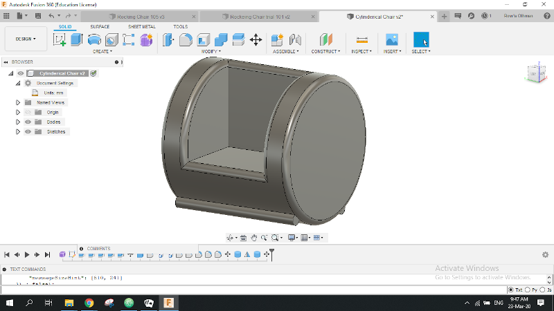
The basic initial idea was a cube cut out of a cylinder with _what I call_ rolling stoppers. :D
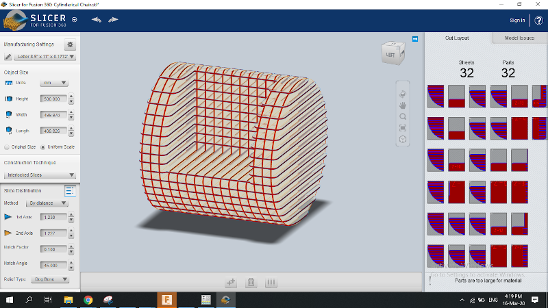
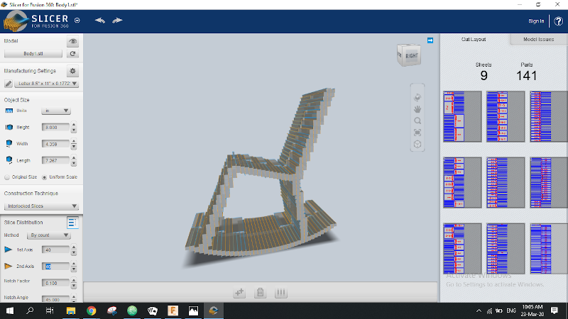
Saved the cylinderical chair as .stl file to slice it with "slicer for fusion 360" as I was planning to manufacture it as interlocked slices.
The reason this design was no good is that normal rocking chair rails / rockers do not have that rounded curvature, it's normaly wider. The cylidrical one would've been called "a rolling chair. 😂😂
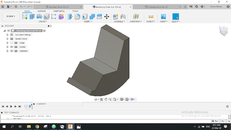
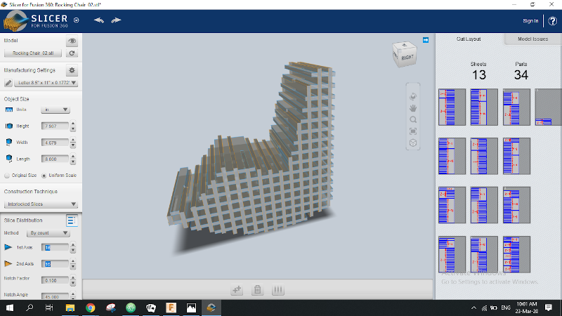
The second trial, I drew a sketch of another bulky profile for a rocking chair with elptical rails.
Tried to slice it into interlocked slices, but it was no good as no matter how much slices I add I wouldn't be able to obtain a smooth rocking movement.
The reason this design was no good was that I couldn't find any slicing method or slices orientation for it to be manufactured and rocking properly.
Here comes the third trial where I drew much slimmer chair profile.
Here was when it also failed to be manufactured in interlocked slices as well.
The reason it failed was that the slicer wasn't abl to create a proper interlocking assembly for such a slim profile.
Then was when I started looking from a different angle. I decided to take a step into smoother curvier designs, I thought that it would be easier _I was wrong on so many levels and soon you're gonna learn why..😂 _
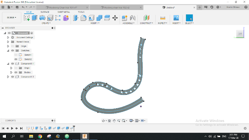
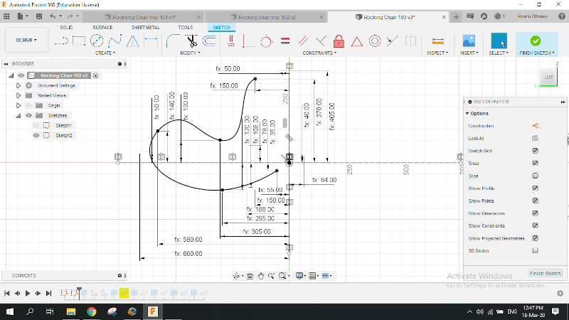
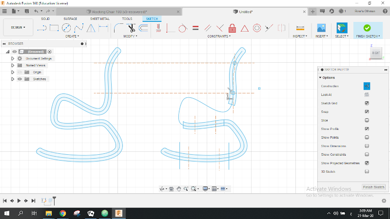
That was my 4th chair trial yet 1st spline design. I thoght it would me more fun, beautiful and musch easier to have curved side profiles and then fix them together by rectangular connections in the back, seat and between the rockers.
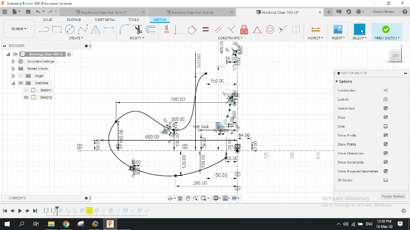
There appeared the big issue, inorder to make a smaller scale model first _to test the chair's functionality_ the design must be parametric and the sketch must be constrained.
It gave me some tough time trying to constrain the spline shape. Why??
It's because every ponit on the spline can only be constrained when you constrain the point itself as well as at least one of the two curvature handles.
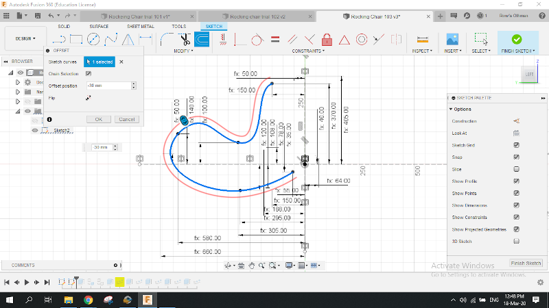
After adding all these dimensions in an attempt to constrain the shape, I created the offset from the constrained spline. Although i thought it was surely gonna be constrained to the original spline by the distance of the offset, it wasn't. 😡
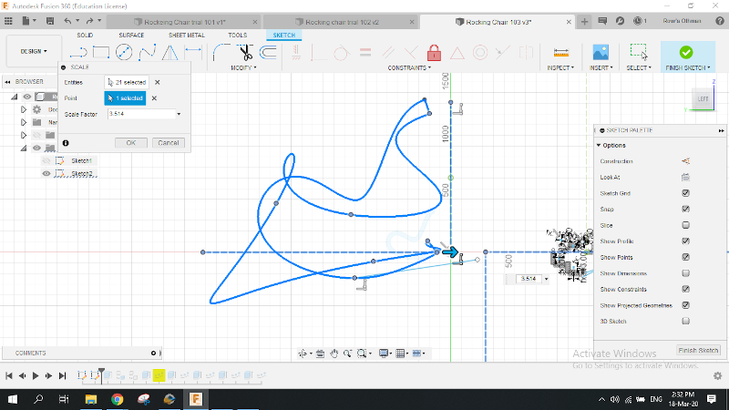
Here was when I thought:" Does it really have to be a parametric design for me to get to scale it?" So I had a copy of the sketch and tried to scale it up to a real size chair. Everything went crazy with the spline points! Inspite of the frustration, I noticed that the offset line was scalled perfectly.
Glad to have discoved about the offset trick & afraid this chair desgin was not stable enough anyway, I decided to change the whole design & get better use of offsets.
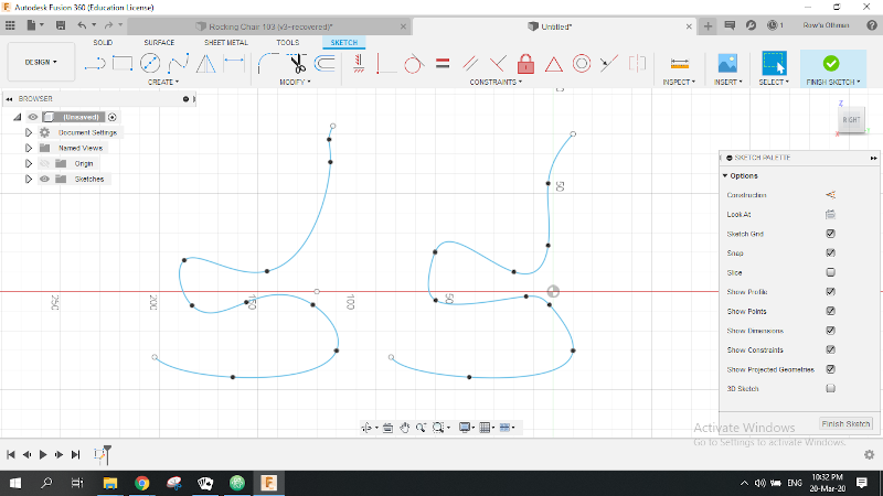
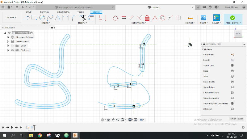
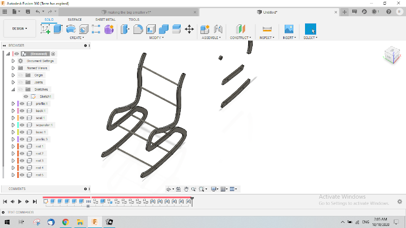
Here comes the fifth and final trial where I tried to add arms and make my chair more stable. The image ddisplays two profiles. I went on with the one on the right.
I offseted the spline with half width on both sides to be able to delete it afterwards. Then I filleted the edges and made a copy of the profile to create the other pieces.
Here was where I devided the copied profile into pieces and started trimming the excess lines.
I started to add the squared slots for the horizontal part that's gonna connect the chair parts together.
I was done adding the slots on all the chair parts to then copy them to the corresponding locations on the side profile.
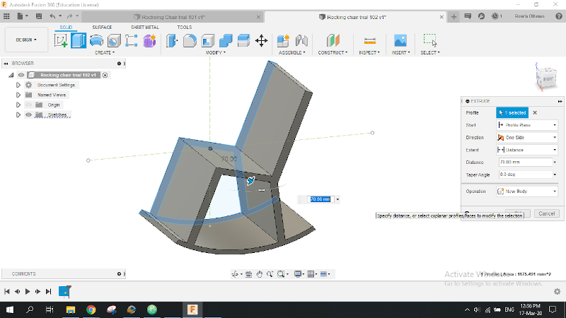
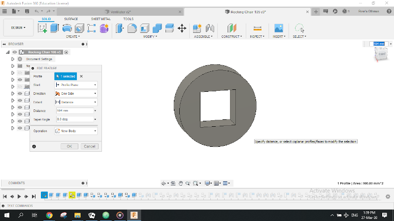
Finished the sketchig and extruded the chair all the chair parts by 18 mm which is the thickness of the wood I'm gonna use.
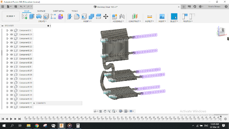
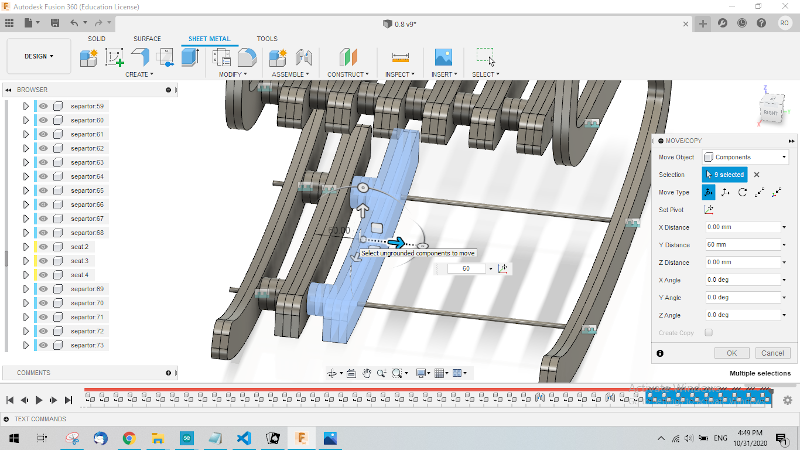
After creating components from all bodies I have, I started assembling my lovely chair. The connecting rods were too long but they were adjusted to the chair width later.
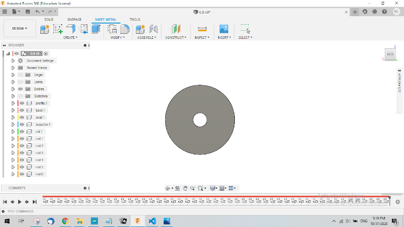
Forgot to mention this special part. I call it "The round separator", it's perpose is to prevent the chair parts from being stacked tightly together resulting in a really dense and heavy chair.
Started assembling the back of the chair on the connecing rod. One piece of round separator and one piece of back.
Captured a screenshot while assembly it wasn't tough although it took me a fair amount of time.
A lot of time passed in lockdown before it was time for implementing the chair, that made me rethink that square rod I made.
The new 40 mm separator with 8 mm hole.
Connecting the two side profiles of the chair with the 8 mm screw rods.
Attaching the back slices of the chair after shortening them a little.
Attaching the last pieces of the rails.
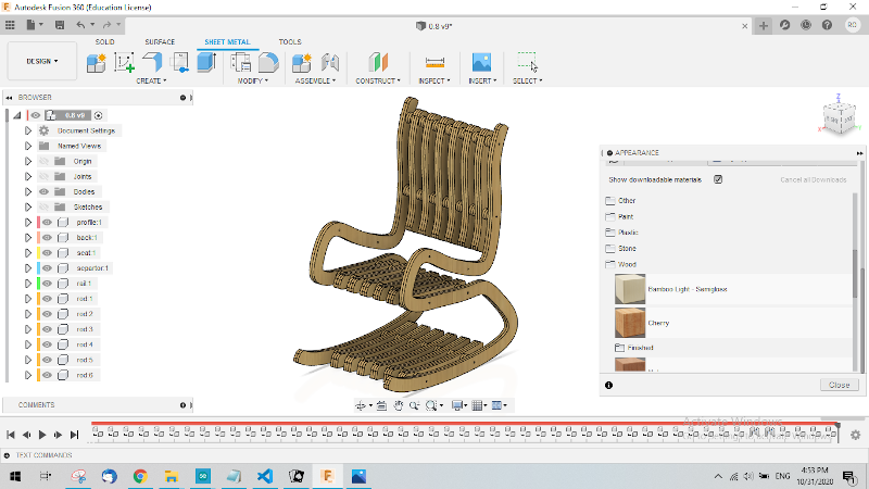
Voilà.. My chair 3D model is done.😍🥳🥳
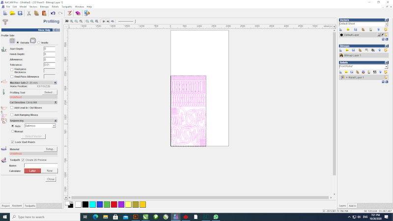
Generating toolpaths:
My Chair.dxf file opened with ArtCAM. I made sure that its scale is correct and it was.
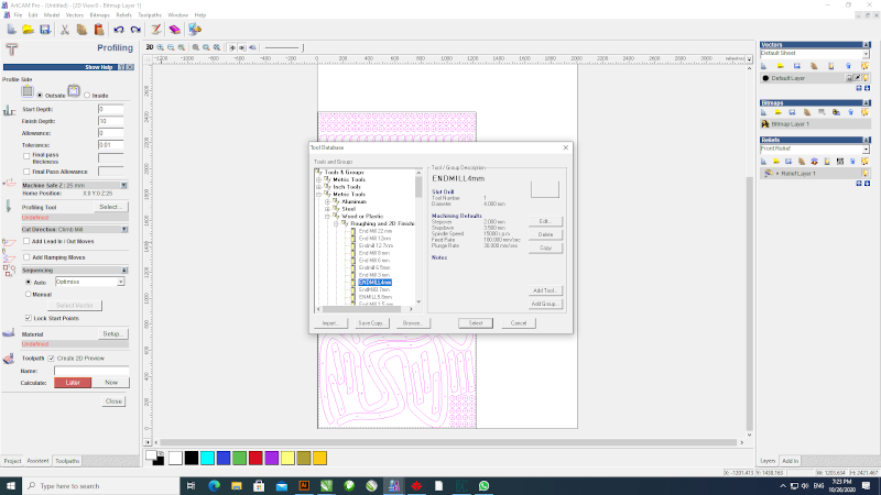
Next step was selecting the appropriate 4mm diameter end mill for roughing and finishing 2D cuts.
Third step was to assign the material thickness. In my case it was 10 mm.
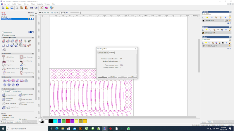
This image shows the number of parts that were going to be milled. 457 piece.
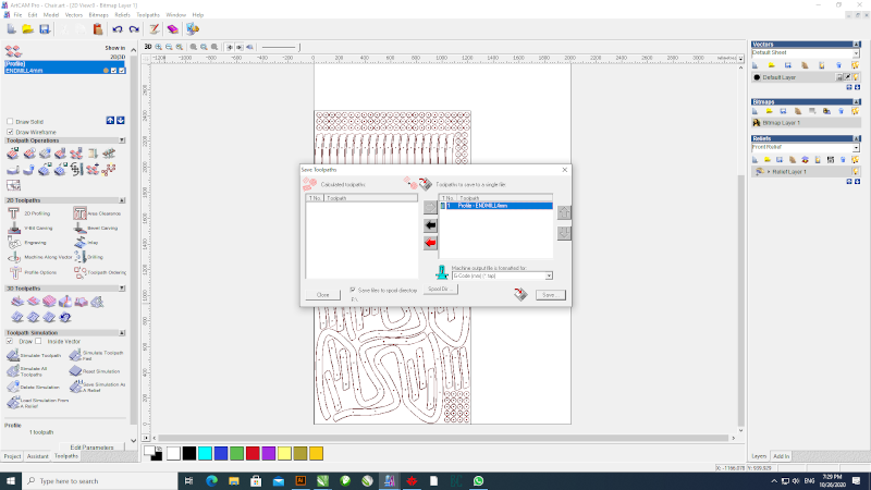
Last step was to save the toolpaths .tap file and get it on a usb flash for the machine.
Machining:
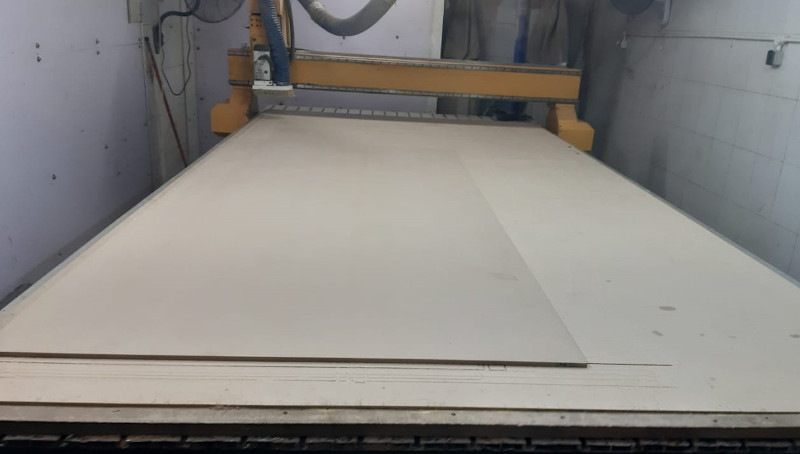
1st step was to fixate the mdf sheet 4 ends on the machine working bed with really small wood nails.
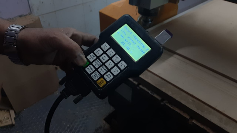
Then we set the origin point and load the toolpaths file.
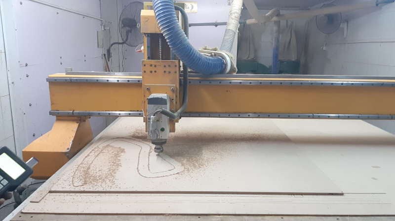
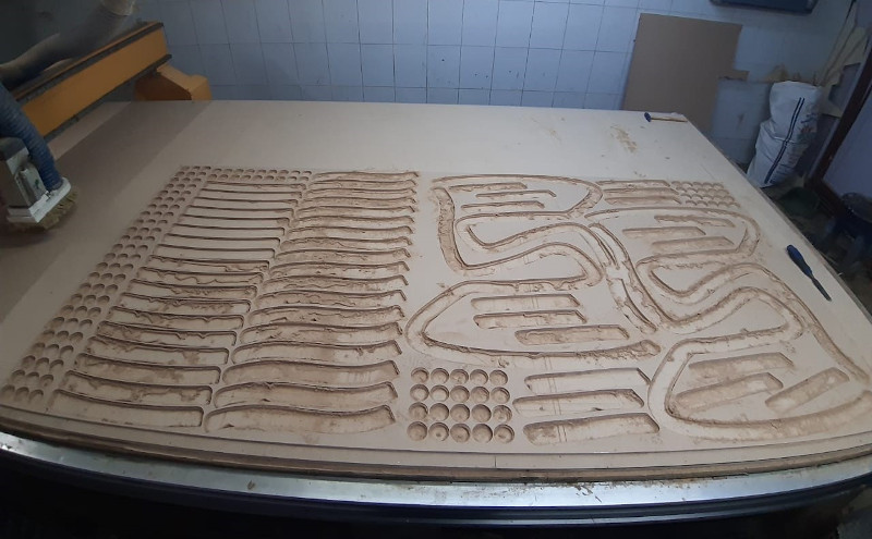
Here is a shot taken after about 3 minutes of milling before attaching the suction tube.
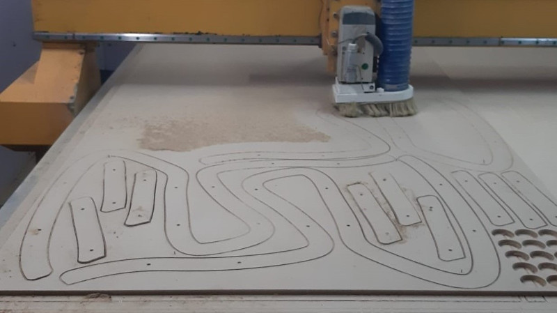
Attaching the tube caused a little problem, the separators were at risk of being sucked up the tube. So I removed them aside once they were cut.
There was when cutting was done after about 1 hour and 35 minutes.
Optimum usage of a sheet of wood. Almost no leftovers.😂
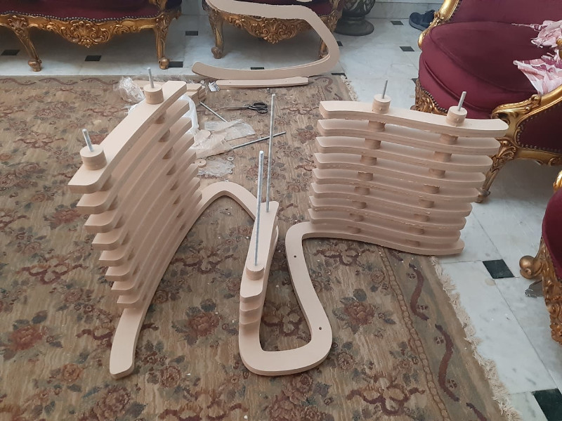
Each and every piece of chair before assembly.
A glimpse of the assembly proccess. I had my little cousins help me with it. It was so much fun. 😊
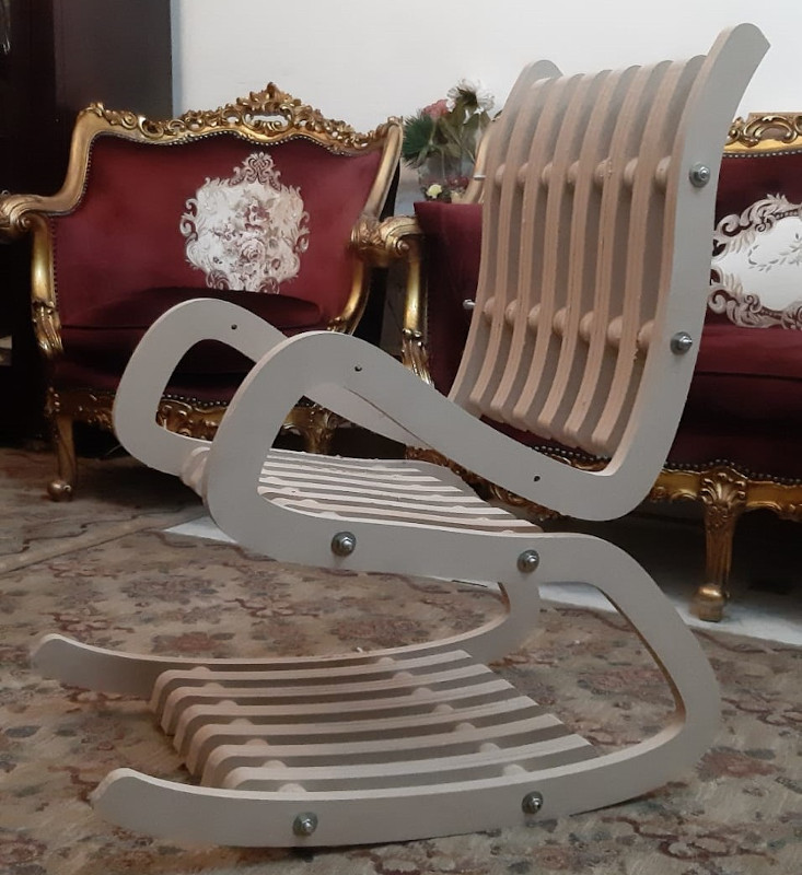
Voilà.. My something big is done.😍🥳🥳
Downloadables: 💾
- Fusion 360 - 3D design fileHere
- Fusion 360 - 2D file .dxfHere
- Toolpaths .tap Here