3D Scanning and printing 📋
🕘 Date / Time:
Heyyyyyy there lovely fellow..^^ , hope life's been good to you ^^. This is our fifth week of Fab Academy and I am getting happier!
We had a group assignment and Individual assignment just like last week. ^^
___________________________________________
A) Group Assignment:
The Assignment was documented on the lab page.
My Reflections:
Saturday morning we started discussing how we’d approach the group assignment. We agreed that each on of us will characterize a one of the printers we have in our lab.
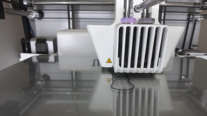
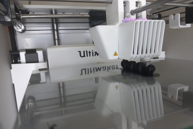
My 3D printer of choice was "Utlimaker 3".
I learnt:
1- More about using Cura 4.4
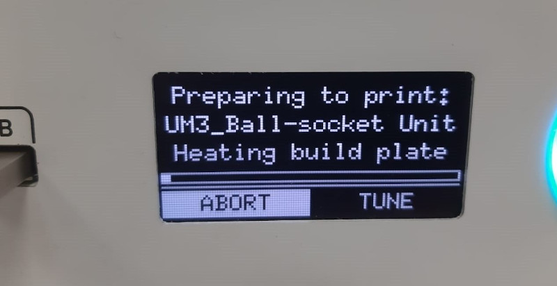
2- How to operate an Ultimaker 3.
3- That the machine takes time to heat up and prepare to print.
4- Printed objects shouldn't be removed off of the printer right away, instead they should get to cool down for a while.
___________________________________________
B) Individual Assignment:
My design idea was to 3D print a joint, as joints can not be manufactured subtractivly in one piece. A ball and socket was my joint of choice as it has the most degrees of freedom among all joints.
3D Printing:
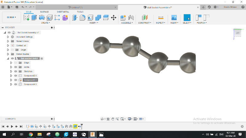
A)Fusion 360:
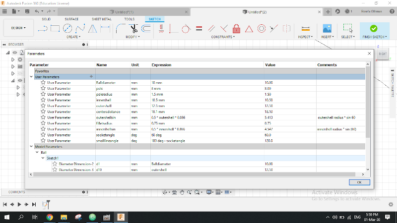
1- Started setting my design parameters.
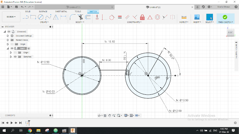
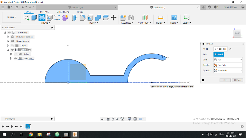
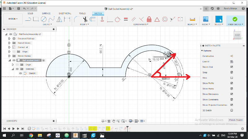
2- Then started sketching my ball and socket joint design.
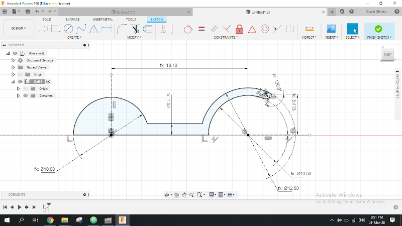
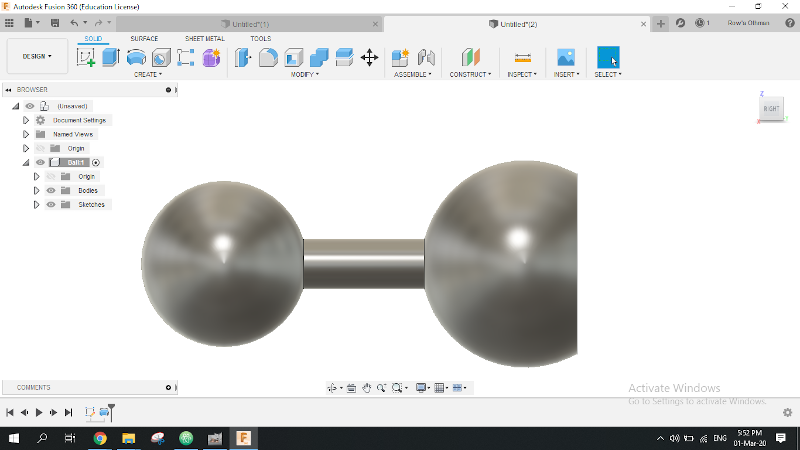
3- Having finshed my sketch, I revolved it around the Y axis to get my 3D unit ready.
4- I copied the body and pasted (Just paste not paste new as all units are going to be identical and we'd need all to follow if we changed the main/ parent unit).
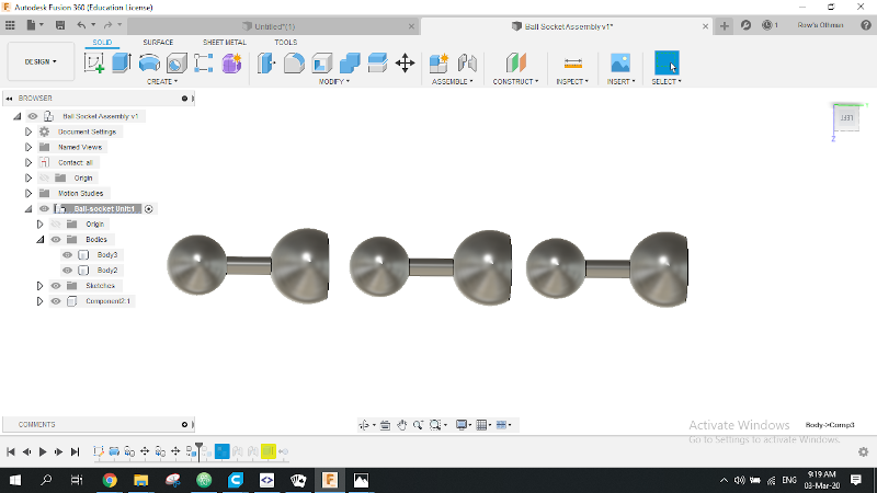
5- Right clicked on each body and chose "Create component from body".
6- Then Joined the 3 components as "ball joints".()
7- From assemble menu "Enable contact set" in order to get the real preview of physical interaction between units.
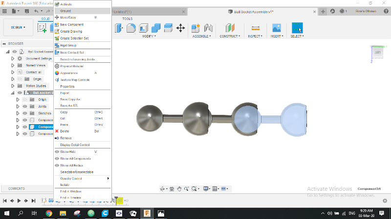
8- Selected the parent unit and grounded it to be able to move the conected units to see how they're going to work.
9- Got the three joints back to their normal aligned position (By getting back a step in the history bar).
10- Left click on the assembled component in the fusion browser and saved it as a ".stl file" to be ready for slicing.
B) Machining:
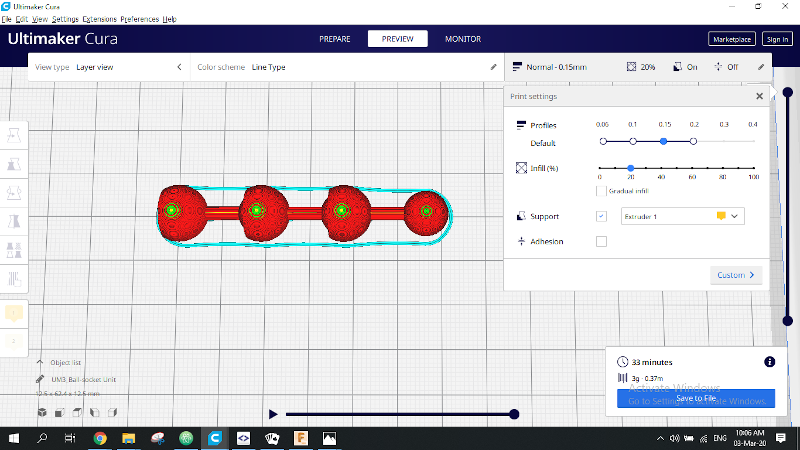
I. Cura 4.4:
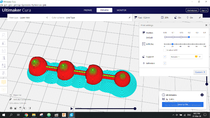
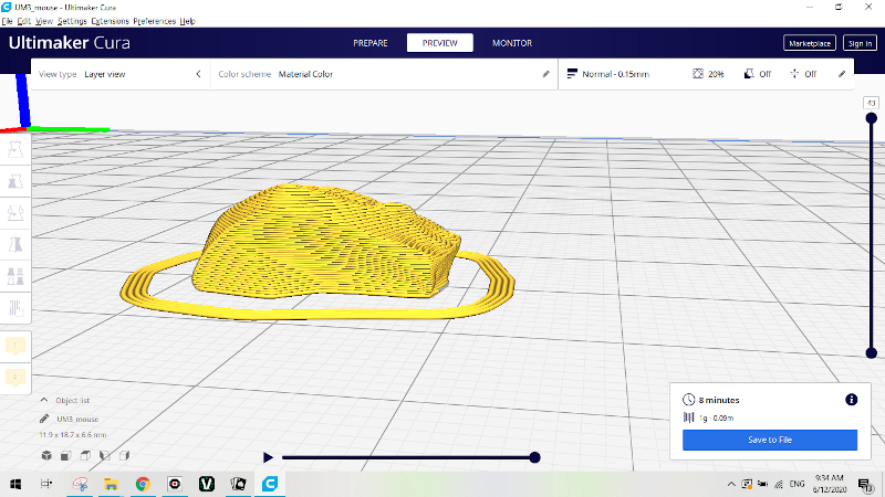
1- Opened the saved ".stl file" with Cura 4.4
2- Selected the type and model of the printer in my lab (Ultimaker 3).
3- Selected the kind of filament I was going to be using (PLA).
4- Chose to print in a normal profile of 0.15
5- Chose to print with 20% infill.
6- Left all other defaults unchanged.
7- Clicked on slice, previewed the item and the estimated time. Finally I saved the file to the Printer's USB flash drive.
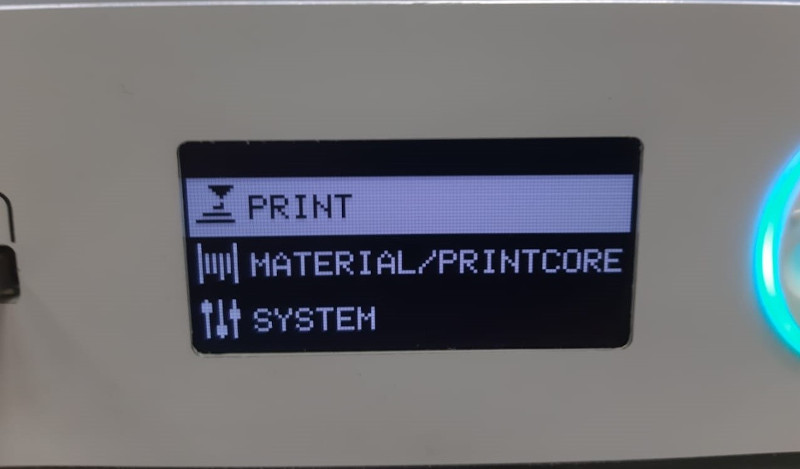
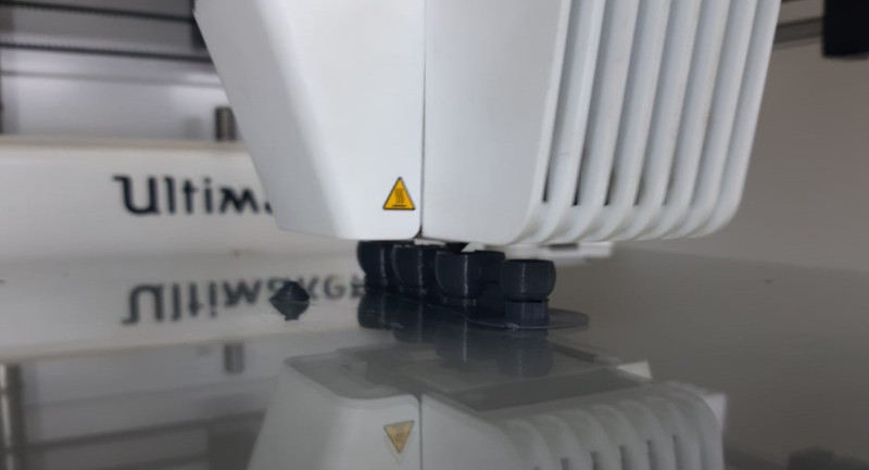
II. Printing:
1- Connected the USB to the Ultimaker 3.
2- Chose Print.
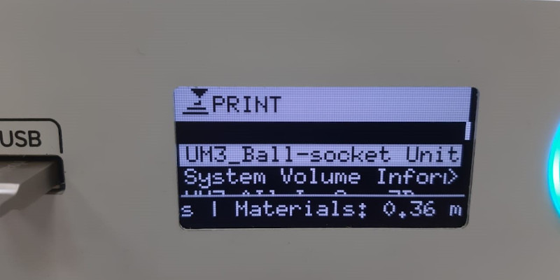
3- Selected my file "Ball-Socket Unit". file
4- Let the printer prepare the file, heat up and do its work.
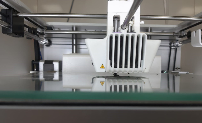
5- Make sure to monitor the printer every now and then to make sure nothing went wrong.
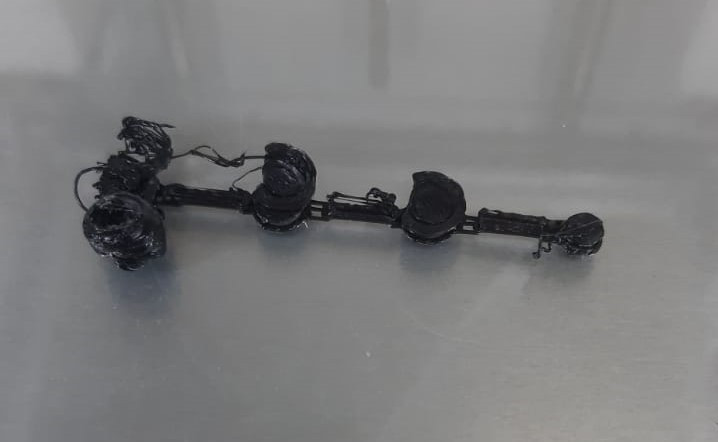
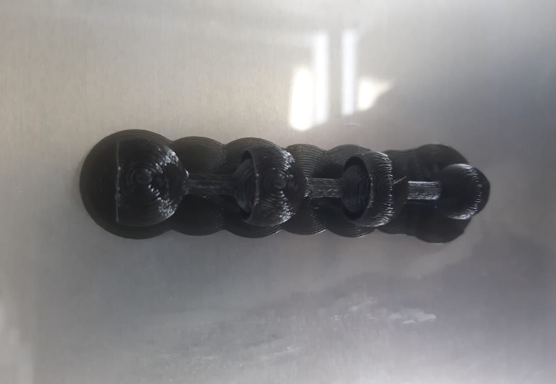
After consulting a college, we came to the conclusion that it failed because there was no adhesion layer beneath it. So that I went back to Cura, added an adhesion layer and started printing one more time.
Reconsulting colleges and instructors, I was hit by the fact. I thought I'd left a 0.5mm clearance between the ball and the socket. I was very wrong! That clearance was 0.25mm each side of the ball! Don't know how I'd overlooked something that obvious!
Third trial:
I changed the parameters of my design so that the clearance on each side equaled 0.35mm and according to our rolation test in the group assignment, 0.3mm clearance was enough for the cube to rotate around the rod. I also increased the pole radius to 2mm instead of 1.5mm as well as the infill, in order to reduce torsional stress on the "pole connecting the ball and the socket" that was obvious when I tried to break the inner supports.
Forth trial:
I knew I needed more clearance and space for the supports to break but I feared the risk of the ball comming out of it's socket. So I decided to alter the design a little bit.
I left 0.75mm of clearance on each side of the ball.
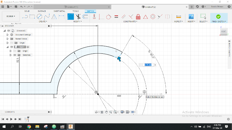
Out of fear that the ball may come out when I increase the clearance, I changed The angle shown in the photo from 60 to 45 degree so as to narrow down the openning of the socket to keep the ball in place.
In Cura I changed the "Support Density" to 5% instead of 15% so that they break and come out easily. That day I was late so that I couldn't monitor the printer whilst working.
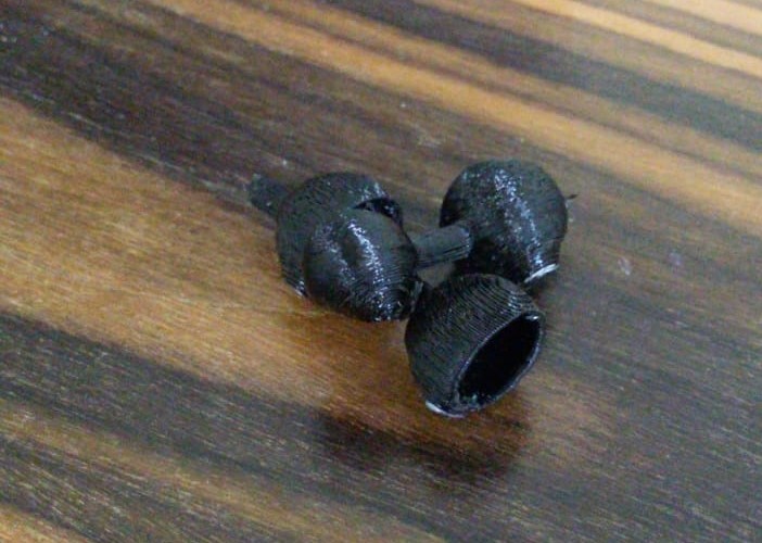
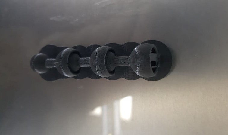
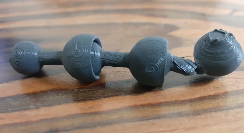
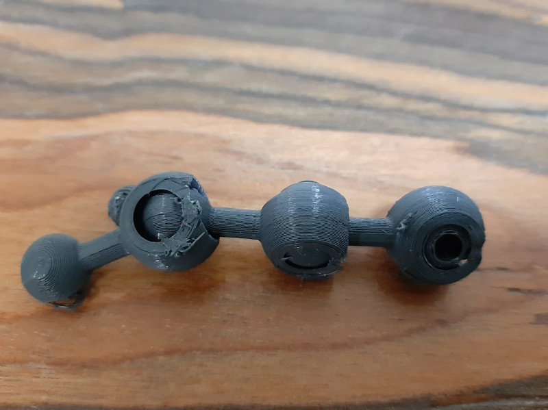
I came next day to find out that something went wrong, so that the print didn't came out perfect but It worked, My joint was moving smoooooooothly!! 😍🎉🎊
Consulting colleges, we came out with the theory that this deformation was a result of high printing speed, triangular infill pattern and high overhang angle.
Fifth and final trial: 🎉😁
Parameters that were altered are the following:
1- Speed from 80 to 50 mm/sec.
2- Infill pattern from triagles to lines.
3- Overhang angle from 60 to 45 degrees.
Started printing one final time.
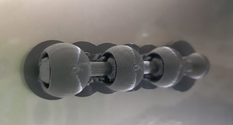
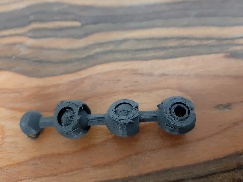
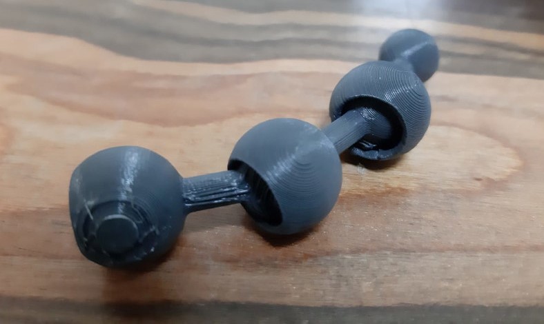
I removed the adhesion layer and was able to break and remove the supports too.It came out perfect!! At last! 🤩🤩
Failures:
1- Overlooking adhesion layer.
2- Too little clearance.
3- Too much supports density.
4- Too much supports density.
5- High speed, too high overhang angle.
___________________________________________
3D Scanning:
Process:
I decided to use my mobile phone for this task. I searched for the top 3D scanning android apps.
The one that I liked was called SCANN3D which I downloaded easily from the play store.
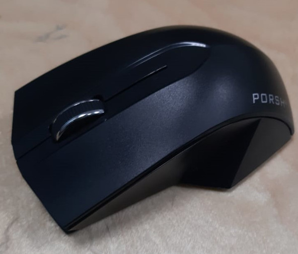
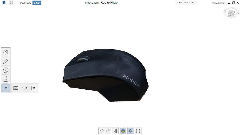
I chose my mouse to be my 3D scanned model.^^
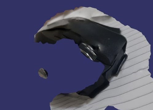
First trial:
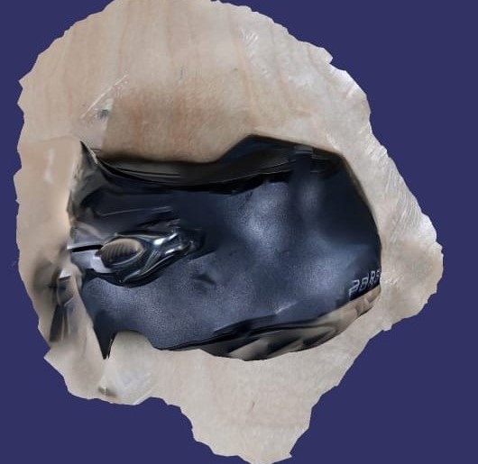
I installed the application, read the precautions, followed the instructions, took exactly 41 images to have my first failed model.😁😁
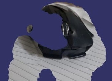
Second trial:
This time I tried better lighting, more uniform background and increased the number of images to 87 images😁😁
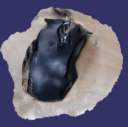
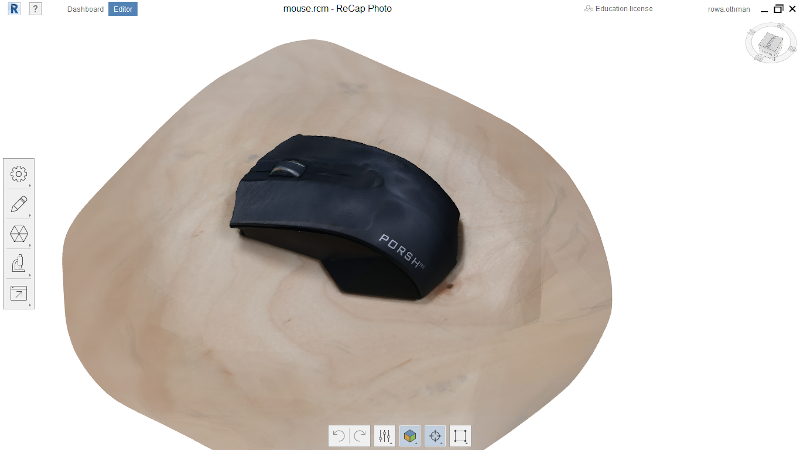
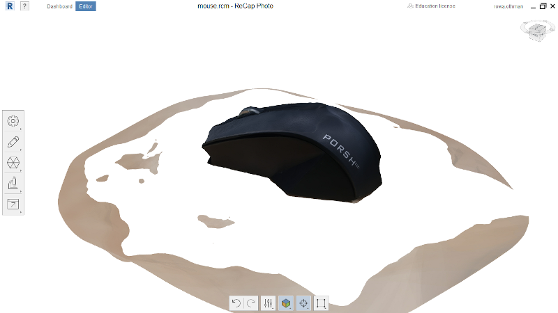
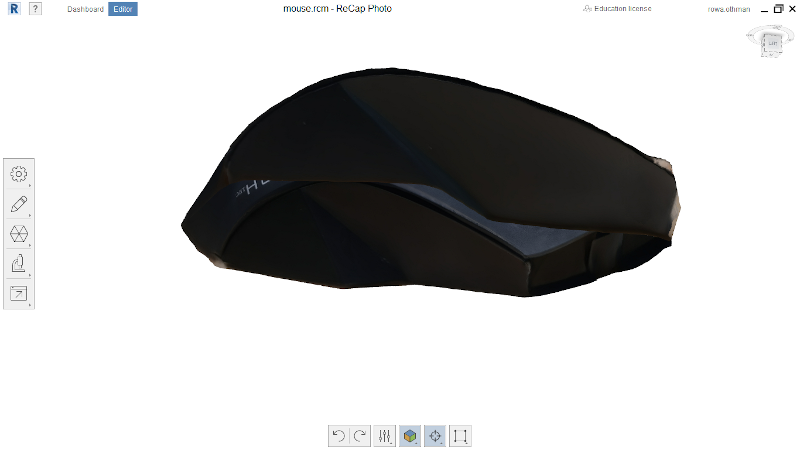
Third trial:
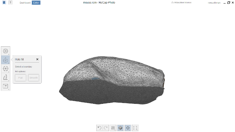
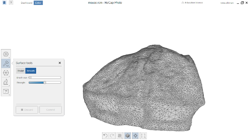
This time I quit using mobile Apps, I took the advice from my college Ahmad Mansour to use the computer software Autodesk Recap using the same 87 images from the previous trial.😁😁
I followed that really simple brief tutorial that lead me through all the process.
Observations:
1- Increased light better gives better results.
2- Increased number of images gives better results.
___________________________________________
Downloadables: 💾
Joint:
Fusion file .f3dBall & socket assembly.
Cura file .stlBall & socket stl.
Mouse:
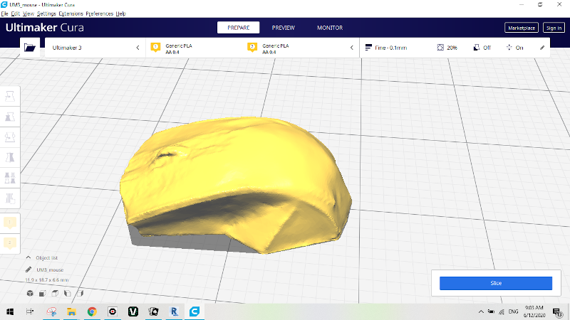
Cura file .stl3d scanned mouse.
©️ Row'a M. M. Othman - Fab Academy 2020