Week 3- Computer Controlled Cutting
Overview
For this week we have two assignments:
- Group assignment
- Individual assignment
to characterize our lasercutter's focus, power, speed, rate, kerf, and joint clearance
Design, lasercut, and document a parametric press-fit construction kit, which can be assembled in multiple ways. Account for the lasercutter kerf. plus cut something on the vinylcutte
At the beginning we start by machine charactrization as a group then I start working on my parametric design on Fusion360, Create flexure part on inkscape, use the laser on my mobile cover and finally cut my studio logo on the vinyle. it was quite a journey I've learned so much and have a lot of fun :)).
My Assignment Steps:
Step (1):Documented how I made my press-fit kit
Step (2):Explained how I parametrically designed my files.
Step (3): Documented how I made my vinyl cutting.
Group Assignment:
Create The Team website for the documentation process.
The Process
Individual Assignments
six month ago I started my journey in the world of digital fabrication the first thing I did back then when I started working with the laser-cutter is to charactrize it and make this simple pressfit kit --> .
please find all my work and documentation about this here
so back in my head I thought it's time to go to the next level. I decided to make flexible part not only on the wood but also on the acrylic Living Hinge plus I want to try the machine with a material I never used before -I choose my mobile cover for this-, but first let's create a new pressfit kit :)
My pressfit kit
The simple way to understand parametric design is to think of as design based on parameters. you could think of Parameters as variables so instead of putting a number in your dimensions, you end up putting the parameters you want, not only that you can even make a relation between your parameters which will give us the flexibility to edit our design, but in a constrain way that we always end up with something that works.
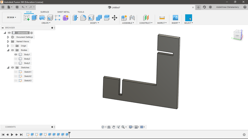
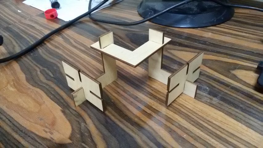
I got inspired from the alphabet letters especially (I,H,L) so I decided to build a legion of spaceships hopefully if I have time I will spray them and give each on of them a name :).
I use Fusion 360 in my design start by creating my parameters, account the laser kerf and save the file as .dxf to use them in RDWorks in order to give the machine the g-code.
The designing process:
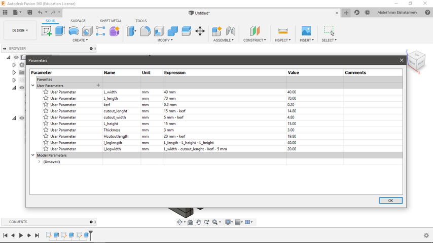
- My design parameters.
- My design on fusion 360.
after finishing the design and cut a one sample of each part I didn't like the L and H final output so I come back and edit the design to end up with the below pictures
- Modified I.
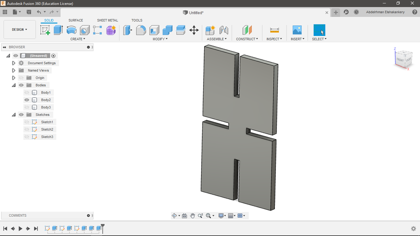
- Modified H.
now it time to cut the final design on the laser so I export my files as .dxf and was going to open them on RDworks and make an array of each piece ,that's when one of my lab colleague Ahmed Hegazy told my about Deepnest.
Deepnest: is an open source nesting application, great for laser that packs your parts into a compact area to save material and time.
it's really simple and easy to use you can download it from the link above and follow the below steps to start :)
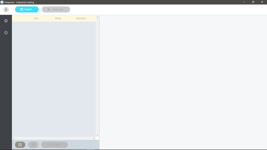
- choose import to add all parts plus a design of a square that equal the size of the sheet your going to use.
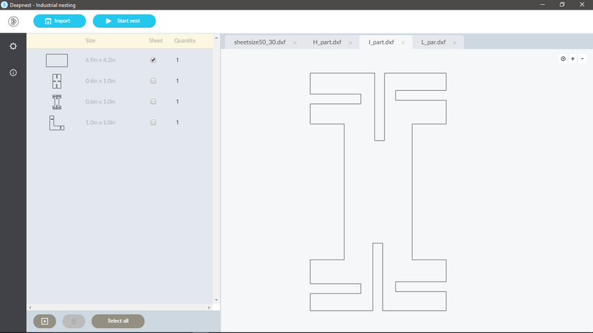
- after add all of your files select the square part as the sheet and change the quantity of the parts.then hit start.
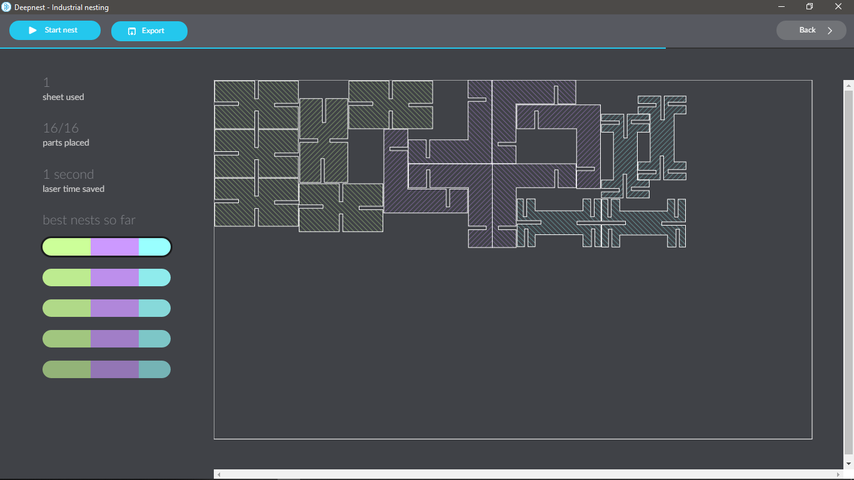
- it will start nesting when you see a compact that you like hit stop and Export your files.
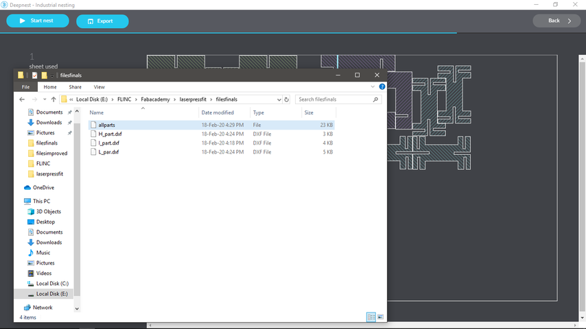
- When I export the file I choose to be .dxf but it exported with no type so you will have to rename it and add the extinsion manually until this bug is solve.
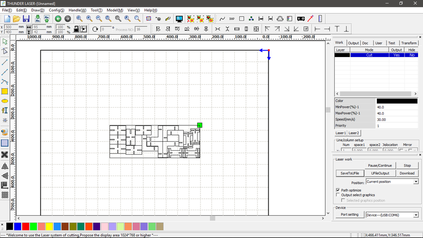
- open RDworks to generate the g-code.
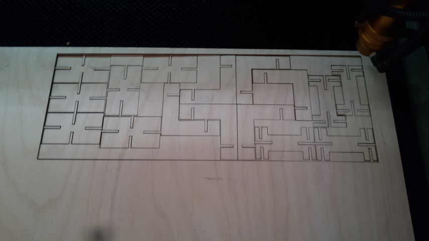
- our machine :).
- Final outputs construction.
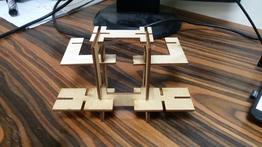
- Final outputs construction.
Living Hinge
living hinge: is another way to use laser cutting to create 3D objects from flat materials. it's more common to use this on wood because the properties of this material allow for a significant degree of flex before the material fractures. but I want to try it also on acrylic and see for myself if it's possible.
as I said before I never try to do living hinge so at the beginning I make sur to understand the science behind this methods.
How to design a living hinge is really an amazing tutorials that explain everything from the concept to the mathematical modelling that we can use to design a better hinge. you can check this tutorial if you want to get more knowledge about hinge mathematical modelling. and here Martin share his results after testing different pattern for the hinge.
unfortunately for me in this short period of time I won't be able to make the calculations myself so I used inkscape extension to create the pattern and see for myself in a try and error process :).
one more thing this pdf laser cut like a boss is really useful and full of amazing insights.
Hinge design process
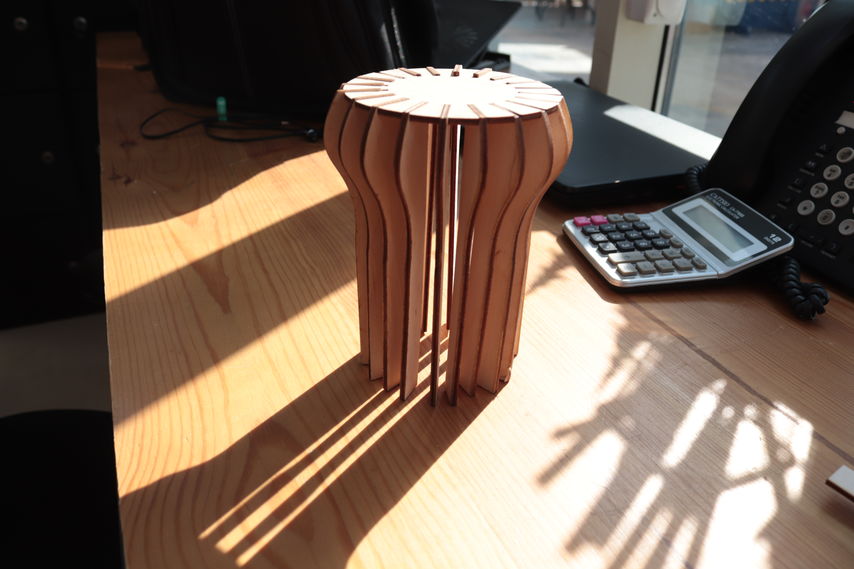
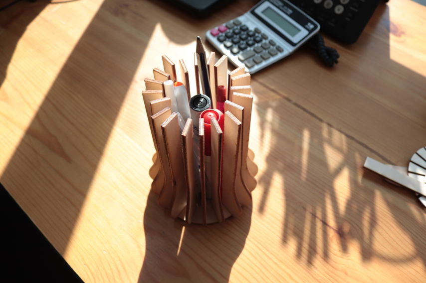
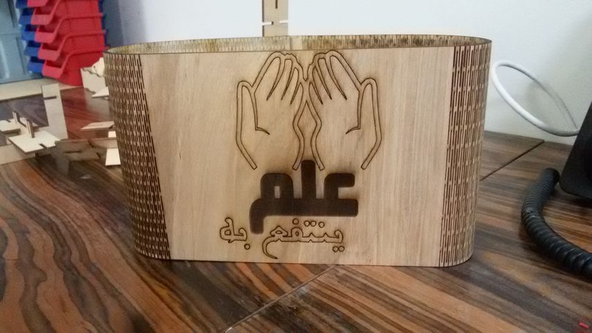
in my head I want to design a lampshade that I will made it's body on laser and it's circuit on the vinyle, so I started designing my body on fusion 360 then import it to inkscape to add the hinge.
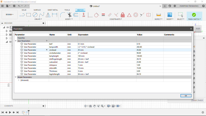
- Create the parameters on fusion 360 for the main part.
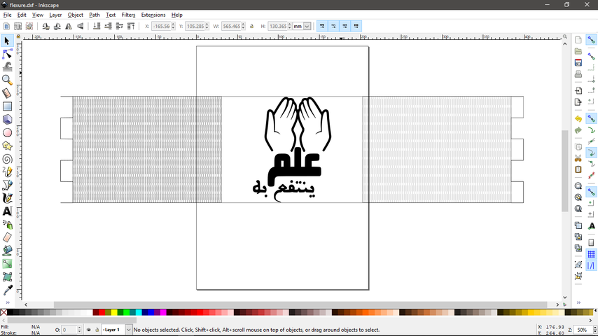
- Import the design to inkscape and use live hinge extension to make the pattern.
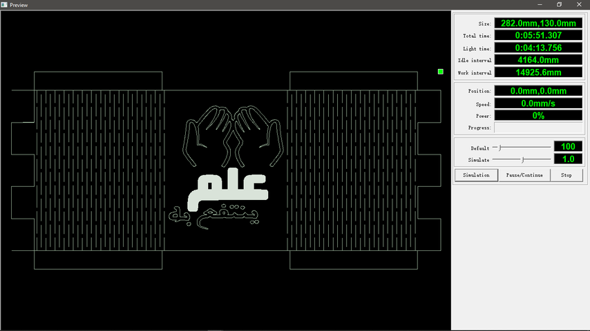
- the simulation process on RD works.
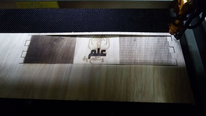
- The machine output.
- will the output turn out very nice from the first trial, however when I import the design to inkscape the size of the part change so it turn out very big , I didn't investigate much to know why this error happened I think I did something wrong in the importing process so take care.
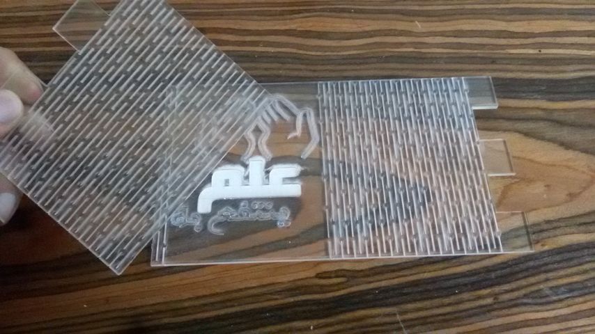
- here is the first try on the acrylic well
after the failure of my first trials on acrylic I got back to inkscape and change the parameters of the hinge and as you can see huge change in flexibality between the two deigns in the video, however I still not satisfied with the final output so the soon I will find time I will try make a mathmatical modelling for the hinge and use it on the acrylic
Laser vs Mobile-cover
time to have some fun and make something new using our machine :) :) .
the idea is really simple I want to engrave the logo of my studio on my mobile-cover. so I export the logo as .dxf using illustrator and measure my mobile cover and try the power and speed first on an old one then it was time to do it for real.
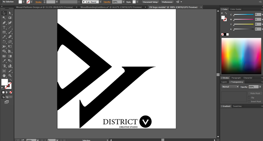
- Export a dxf file of the logo from illustrator.
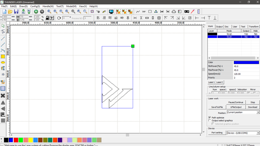
- open RD works place the logo inside a rectangle = the size of the mobile cover.
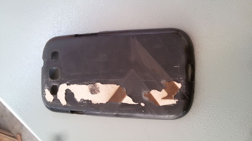
- first I try the power and the speed on an old mobile case.
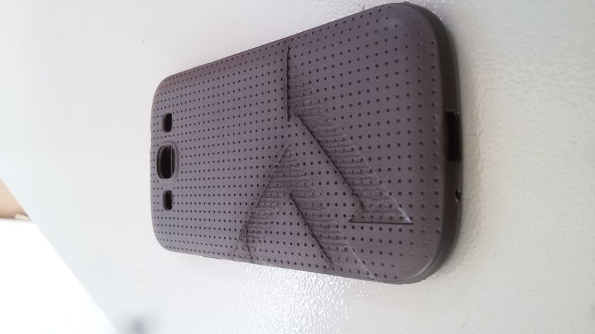
- final output with power=20,speed=180.
Vinyle Cutter
The vinyl is very simple and really easy to work with it didn't take time at all to understand how to operate it or even how to use Roland cut for making the deisgn we want
I wanna create a pcb circuit on the vinyle for the lampshade, also wanna try to make a printed design for T-shirt but because of the limited time we have in the academy for now I will cut my studio's logo and place it on my laptop.
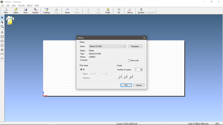
- open Roland cut and select our machine.
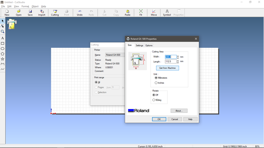
- adjust the picture setup.
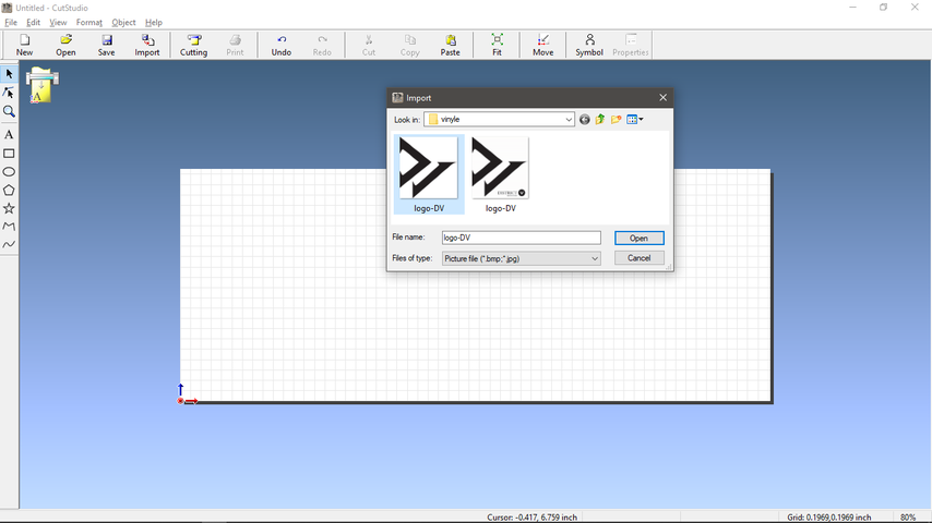
- import the logo.
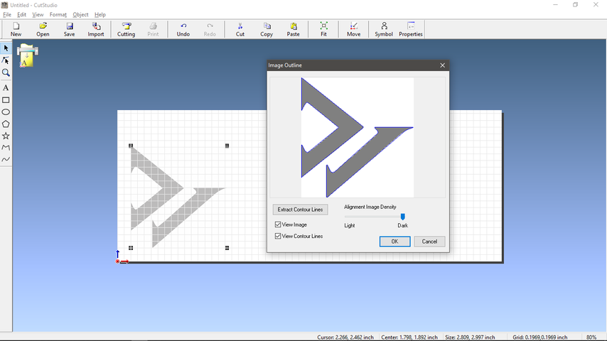
- create the outlines.
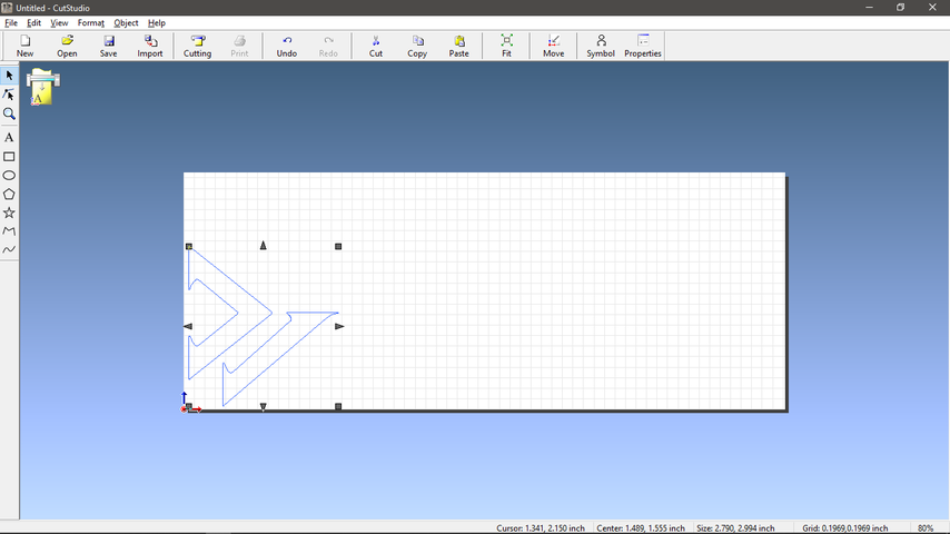
- remove the picture then choose cut.
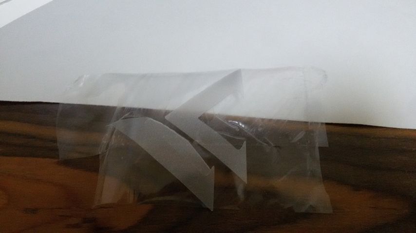
- after finished use a tap to remove and place the logo.
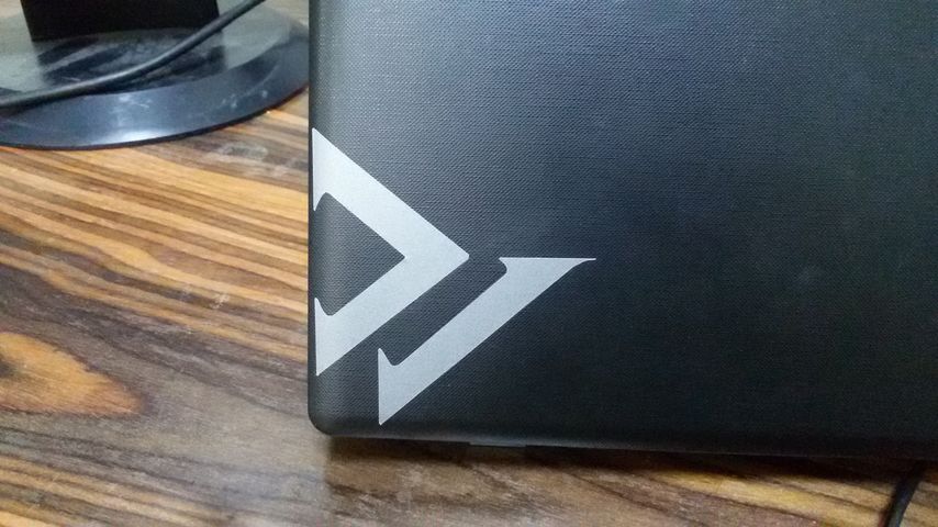
- final Output :)) .
Group Assignments
Please find our work on our group page Fab Lab New Cairo.
Files:
Find below the files that I made for this assignment. Please do not hesitate to download it!!