Test runout, alignment, speeds, feeds, and toolpaths for your machine. view page
Learning Outcomes
1) Understand 2D design development for CNC production. 2) Design a furniture within the constraints and minimum use of wood. 3) Hands on shopbot. 4) Learn how to make tool paths.
Individual Assignment
Shopbot 3-axis CNC milling machine
Shotbot is a CNC (Computer Numerically Controlled) machine that can be used for milling and cutting of wood, plastic, metals and other materials powerfully, precisely and affordably.
Drill Bits vs End Mills
The figure on the left side shows a drill bit plunging axialy, Drill bits are mainly used to cut out holes.
The figure on the right side shows an end mill removing material at a certian depth horizontaly.
Flat / Ball end mills
flat end leaves flat surface profile on the stock and are good for removing large volume of material, but steps are formed when used for making curved surfaces. Ball end leaves curved surfaces and forms smooth curved finish while cutting cavities. They are used for finishing cuts.
Chip load :- This is the amount of material that is removed in each chip. The value is approximately = feed rate (inches per minute) / (RPM x number of flutes)
Cut depth :- This is the measure of how deep the end mill should go in each step while milling. Ideally cut depths should be less than 1/3rd of the length of the tool. They are mentioned in the product manual of the tool bits.
Step over :- In a pocket cut the machine will traverse the entire area of the cut. It does that with a series of paths that cover the entire length and width of the cut. While doing this the step over determines how much the adjacent paths overlap each other. Usually we use it at 50%, ie the adjacent end mill cuts will overlap 50%, which gives a better finish.
Designing
For my Individual Assignment, I wanted to make a furniture that is simple and unique by using wood minimum as possible. So I thought of making a combo of a table and chair, ie, a table to which a chair is attached.
I watched a youtube tutorial on how to design a shelf using fusion 360. It was very helpful because the video shows how to set parameters and shows how to make finger joints and pockets easily and many more shortcuts and tools.
Using fusion 360 I designed the central structure for the table and chair combo.
Then I extruded the structure to the thickness of the plywood.
Then I designed and extruded the center support and the table and chair.
Gave pockets for interlocking.
Gave Dogbone to all the inside edges.
I made a prototype of my design on a cardborad by lasercutting.
Then I understood my design had few problems. The table was not stable, it has tendenacy to twist. The support for the chair is not proper, if the load get concentrated to any corner then the whole furniture will colapse. And moreover I didn't like the design too, It came out very simple and old fashion.
I need to make a design of my concept furniture that doesn't twist or turn or collapse and moreover it should look good. Many design came into my mind, but I didn't want to make my design complicated. It should be simple and at last I ended up with this. So I redesigned the center structure.
Extrude the structure.
Designed the table and chair.
Designed the leg for the table and chair.
Extruded the legs.
Made the pockets for interlocking.
Gave dogbones to all the inner edges.
I made prototype and it came out well.
Material usage was a big concern for me. So I alligned the parts on a 8X4ft sheet and found out that my design only consumes half of the plywood sheet. That means I could make 2 sets of table and chair using 1 plywood.
Setting the tool path
Before we start to mill, We have to first set the tool paths for milling various parts. In our lab we use the software 'Vcarve' for setting tool paths and to generate G-codes.
I uploaded my design which is a .dxf file into the vcarve software.
Then I checked whether all the line are continuous by clicking the lines.
Here when I selected a line the object didn't get selected, Its because the object is not continuous. If we give this object for milling it won't get milled properly. So its important to join all the lines and make it continuous. Use the join tool in the tool bar and select all the line and join it
Then I grouped the object which requires the same milling operation, for expample, I grouped the half pockets together so that I can mill those pockets at a certain cut depth, I grouped the other tabs together so that I can perform inside profile at full depth and I grouped the other parts so that I can perform outside profile mill at full depth.
I gave tabs to the parts so that during milling the parts won't displace.
I made the tool paths for each operations as different files and saved it as :
Screw hole - Drill holes on the plywood board for mounting the board to bed
Pocket Tab - Mill out the 6mm depth inside pockets
Tab - Mill out the 12mm depth inside pockets
Parts - Mill out the outline of all the parts
Milling
The shopbot in our lab have a bed size of 8X4ft. The mill can move along the X,Y Z axis. We have given a sacrificial layer of MDF of thickness 12mm over the bed. The sacrificing layer also protect the milling bit from damage by avoiding unwanted intereference with the metal body.
The shopbot comes with a huge vacuum cleaner to suck out the debris during milling process. It is an important part of the machine because the fine particales of dust that comes out the material during milling can cause respiratory problems.
It is very important to wear safety gears while using the machine, So always wear a pair of gloves, goggels, earphones or ear plugs and boots.
Shopbot has a wired remote which consist of an emergency button, A reset switch and a spindle start button.
All the electronics are integrated in to the shopbot main control box.It has an ON/OFF switch and also a key to enable the spindle.Shopbot also has an additional emergency stopbutton to place on the other side. So that user could access energency button easly from both side of the machine.
To fix the end mill to the spindle we need these tools.
First insert the collet into the lock nut and fix the lock nut to the spindle, do not tighten it now. Insert the end mill through the collet and tighten the lock nut using the spanner and the lock nut tool.
To prevent accidental turning on the spindle while we work on the chuck . The key for the spindle is attached to the lock nut tool.
The ShopBot software has a simulated DRO(Digital read out) and it has 3 main parts
A position fedback main window .It shows the status of all the functional parats of the machine.
A simulated keypad for manual jogging and setting origins
An Integrated command console.
For setting the origin, Jogg the endeffector to the desired origin point and click in the zero axis button .Select X and Y axis and set to zero.To set the Z axis move the endeffector tho the center of the board . For zeroing the z axis we are using the automatic methode place the zeroing plate directly under the milling bit .Connect the clip to the spindil and click the z Calibration button
First I milled the screw holes, and then screwed the ply board on to the bed.
Then I milled out the pockets.
Then I milled out the outline.
Assembling
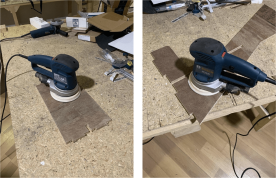
Using the orbital sander I sanded the plywood and its edges to get a smooth finish