Week 14

Embedded Networking and Communications

Objectives

Individual Assignment
design, build, and connect wired or wireless node(s) with network or bus addresses

Group Assignment
Send a message between two projects
view page

Learning Outcomes
Demonstrate workflows used in network design
Implement and interpret networking protocols and/or communication protocols

Individual Assignment

This weeks assignment is to create a network using our custom PCB boards using a wired or wireless connection. I decided to do a I2C wired protocol, I felt these are very useful while I am doing a modular project or while I needed to extent the pins of my microcontroller. Also a lot of I/O devices use these protocoles to minimize the difficulty of hardware designing and also to minimize the number of pins.

I2C Communication
I2C combines the best features of SPI and UARTs. With I2C, you can connect multiple slaves to a single master and you can have multiple masters controlling single, or multiple slaves. This is really useful when you want to have more than one microcontroller logging data to a single memory card or displaying text to a single LCD. I2C is a serial communication protocol, so data is transferred bit by bit along a single wire (the SDA line).
I2C only uses two wires to transmit data between devices:
  • SDA (Serial Data) – The line for the master and slave to send and receive data.
  • SCL (Serial Clock) – The line that carries the clock signal.


BOARDS
For communication I need atleast 2 boards minimum.
  • Master Node - Generates the clock and initiates communication with slaves.
  • Slave Node - Receives the clock and responds when addressed by the master.


For conducting I2C communication, I'm planning to use the boards I made for my previous assignments.
I selected the Presence Board I made for the INPUT DEVICES week as the Master Node.


While designing the input board, I gave an I2C port and I also gave pull up resistors(R3 and R4) between VCC and the SDA and SCL line respectively.
https://rheingoldheavy.com/i2c-pull-resistors/

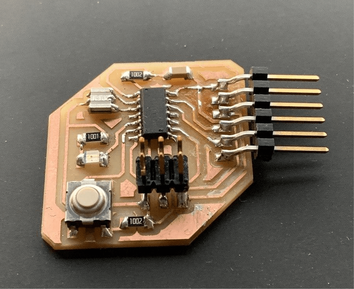
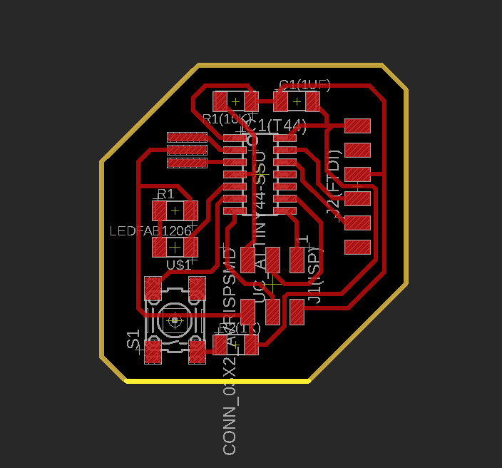
I selected the Hello Echo Board I made for the ELECTRONICS PRODUCTIONS week as the Slave Node.


PROGRAMMING
I programmed the Master node to check presence using the ultrasonic sensor, If the ultrasonic sensor senses presence within 10cm, the master will send signal to the slave and the LED on the slave will glow.

Master Program
                #include <Wire.h>
                #include <SoftwareSerial.h>
                
                #define trigPin 3
                #define echoPin 2
                #define RX 1
                #define TX 0
                
                SoftwareSerial window(RX, TX);
                
                void setup() 
                {
                  pinMode(trigPin, OUTPUT);
                  pinMode(echoPin, INPUT);
                
                  window.begin(9600);
                  
                  Wire.begin();
                }
                
                void loop() 
                {
                 long duration, distance;
                
                  digitalWrite(trigPin, LOW);
                  delayMicroseconds(2);
                  digitalWrite(trigPin, HIGH);
                  delayMicroseconds(10);
                  duration = pulseIn(echoPin, HIGH);
                  distance = (duration/2) / 29.1;
                  
                  if(distance <= 10)
                  {
                    Wire.beginTransmission(8);
                    Wire.write(1);
                    Wire.endTransmission();
                    window.println("Human within 10cm");
                  } 
                
                   else if(distance > 10 && distance <=30)
                  {
                    Wire.beginTransmission(8);
                    Wire.write(0);
                    Wire.endTransmission();
                    window.println("Human within 30cm");
                  }  
                 delay(5000); 
                }


Slave Program

                #include <Wire.h>
                
                #define led1 3
                
                void setup() 
                {
                  pinMode(led1, OUTPUT);
                  
                  Wire.begin(8);
                  Wire.onReceive(receiveEvent);
                }
                
                void loop() 
                {
                  delay(100);
                }
                
                void receiveEvent() 
                {
                  int x = Wire.read();
                  if (x == 1)
                  {
                    digitalWrite(led1, HIGH);
                  }
                  
                  else if (x == 0)
                  {
                    digitalWrite(led1, LOW);
                  }
                }


I then flased the programs to the respective boards.

CONNECTION


I connected the Master Node and the Slave Node using the jumper wires.