Add an output device to a microcontroller board you've designed and program it to do something
Group Assignment
Measure the power consumption of an output device view page
Learning Outcomes
Demonstrate workflows used in controlling an output device(s) with MCU board you have designed
Individual Assignment
An output device is any piece of computer hardware equipment which converts information into human-readable form. It can be text, graphics, tactile, audio, and video.
Some of the output devices are Visual Display Units (VDU) i.e. a Monitor, Printer, Graphic Output devices, Plotters, Speakers etc. A new type of Output device is been developed these days, known as Speech synthesizer, a mechanism attached to the computer which produces verbal output sounding almost like human speeches.
Some examples of output devices are given below: [WiKi]
Monitor
Printer
Speaker
Headphones
Projecter
GPS
Sound Card
Video Card
OMR
Braille reader
This weeks assignment is to design a PCB to make an output device that can do some operation. So I decided to make and program a board to operate a stepper motor, becuase my final project need stepper motors for its function.
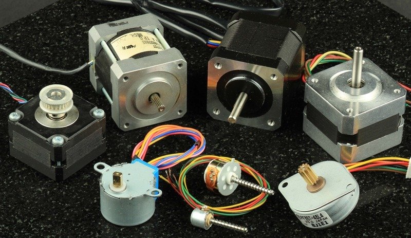
STEPPER MOTOR
A stepper motor, also known as step motor or stepping motor, is a brushless DC electric motor that divides a full rotation into a number of equal steps. The motor's position can then be commanded to move and hold at one of these steps without any position sensor for feedback (an open-loop controller), as long as the motor is carefully sized to the application in respect to torque and speed.
Stepper motors move in discrete steps. They have multiple coils that are organized in groups called "phases". By energizing each phase in sequence, the motor will rotate, one step at a time. With a computer controlled stepping you can achieve very precise positioning and/or speed control. For this reason, stepper motors are the motor of choice for many precision motion control applications.
There are two basic winding arrangements for the electromagnetic coils in a two phase stepper motor:
Bipolar Bipolar motors have a single winding per phase. The current in a winding needs to be reversed in order to reverse a magnetic pole, so the driving circuit must be more complicated, typically with an H-bridge arrangement (however there are several off-the-shelf driver chips available to make this a simple affair). There are two leads per phase, none are common.
A typical driving pattern for a two coil bipolar stepper motor would be: A+ B+ A− B−. I.e. drive coil A with positive current, then remove current from coil A; then drive coil B with positive current, then remove current from coil B; then drive coil A with negative current (flipping polarity by switching the wires e.g. with an H bridge), then remove current from coil A; then drive coil B with negative current (again flipping polarity same as coil A); the cycle is complete and begins a new.
Unipolar A unipolar stepper motor has one winding with center tap per phase. Each section of windings is switched on for each direction of magnetic field. Since in this arrangement a magnetic pole can be reversed without switching the direction of current, the commutation circuit can be made very simple (e.g., a single transistor) for each winding. Typically, given a phase, the center tap of each winding is made common: giving three leads per phase and six leads for a typical two phase motor. Often, these two phase commons are internally joined, so the motor has only five leads.
STEPPER MOTOR DRIVER
A stepper motor driver (or stepper motor drive) is a circuit which is used to drive or run a stepper motor. It is often called a stepper motor driver. A stepper motor driver usually consists of a controller, a driver and the connections to the motor.
Nowadays, people are moving away from discrete driver components like transistors to more compact integrated IC’s. These driver IC’s are available at reasonable costs and are easier to implement in terms of assembling which improves the overall design time of the circuit. The drivers must be selected to suit the motor ratings in terms of current and voltages.
In our lab we have Pololu A4988 stepper driver. This product is a carrier board or breakout board for Allegro’s A4988 DMOS Microstepping Driver with Translator and Overcurrent Protection. This stepper motor driver lets you control one bipolar stepper motor at up to 2 A output current per coil.This carrier has reverse power protection on the main power input and built-in 5 V and 3.3 V voltage regulators that eliminate the need for separate logic and motor supplies and let you control the driver with microcontrollers powered at 5 V or 3.3 V.
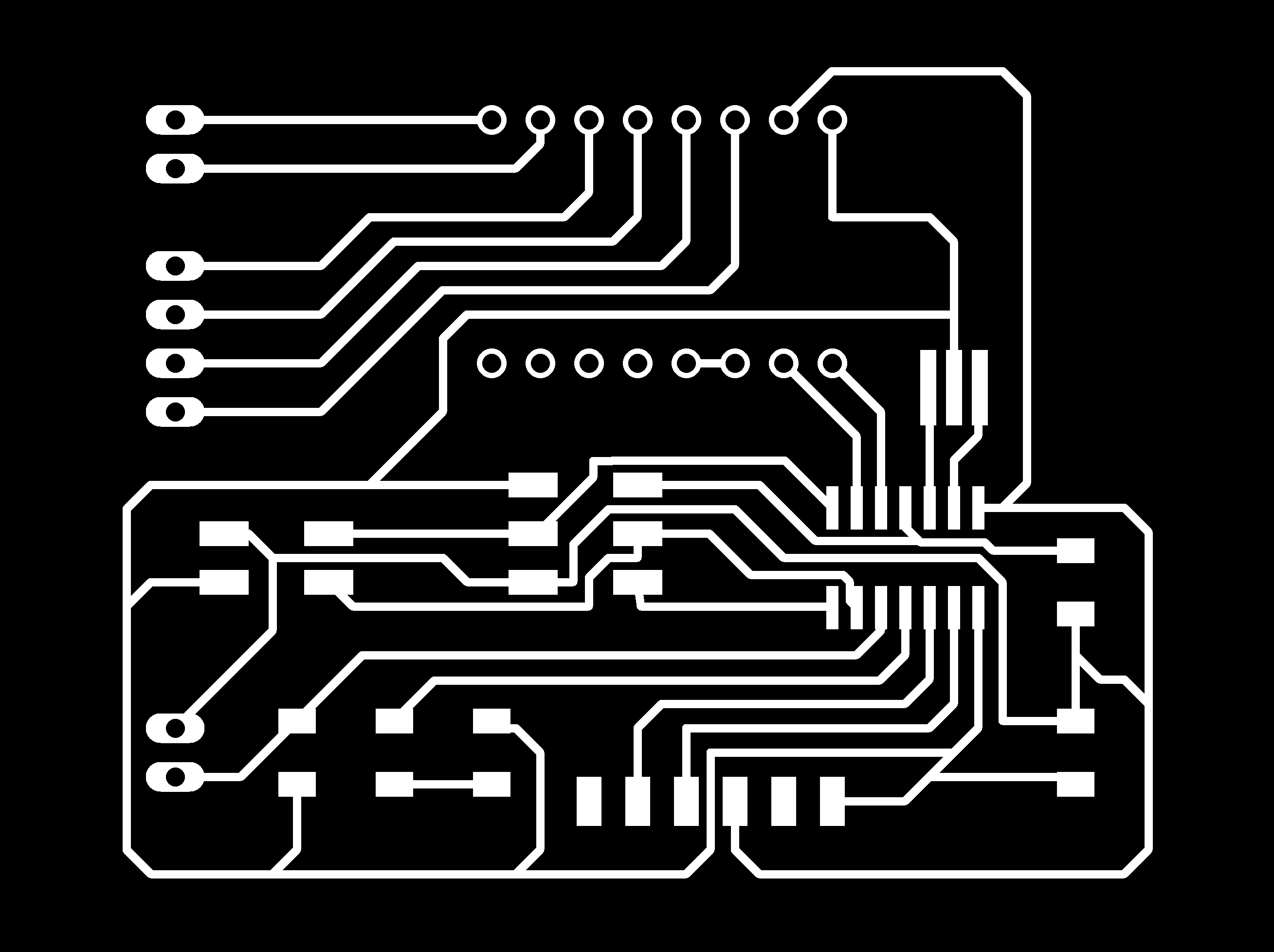
PCB Designing
For designing the PCB circuit I used AUTODESK EAGLE. I used ATtiny44 as the microcontroller, I also included a 2x2 Pin Head for I2C communication for future so that I can use this same board for Embedded Networking and communication week.