
|

| Sukkur IBA University Merit, Quality, Excellence |
Week - 15
Wildcard Week
Assignment
- Design and produce something with a digital fabrication process (incorporating computer-aided design and manufacturing) not covered in another assignment, documenting the requirements that your assignment meets, and including everything necessary to reproduce it. Possibilities include (but are not limited to):
CAD Designing On Solid Work
This week is wild card week, and I'd want to make an umpire cap for myself.First, I opened Solid Work and created a new file name as a umpire cap, and then I set up the plan in Solid Work.
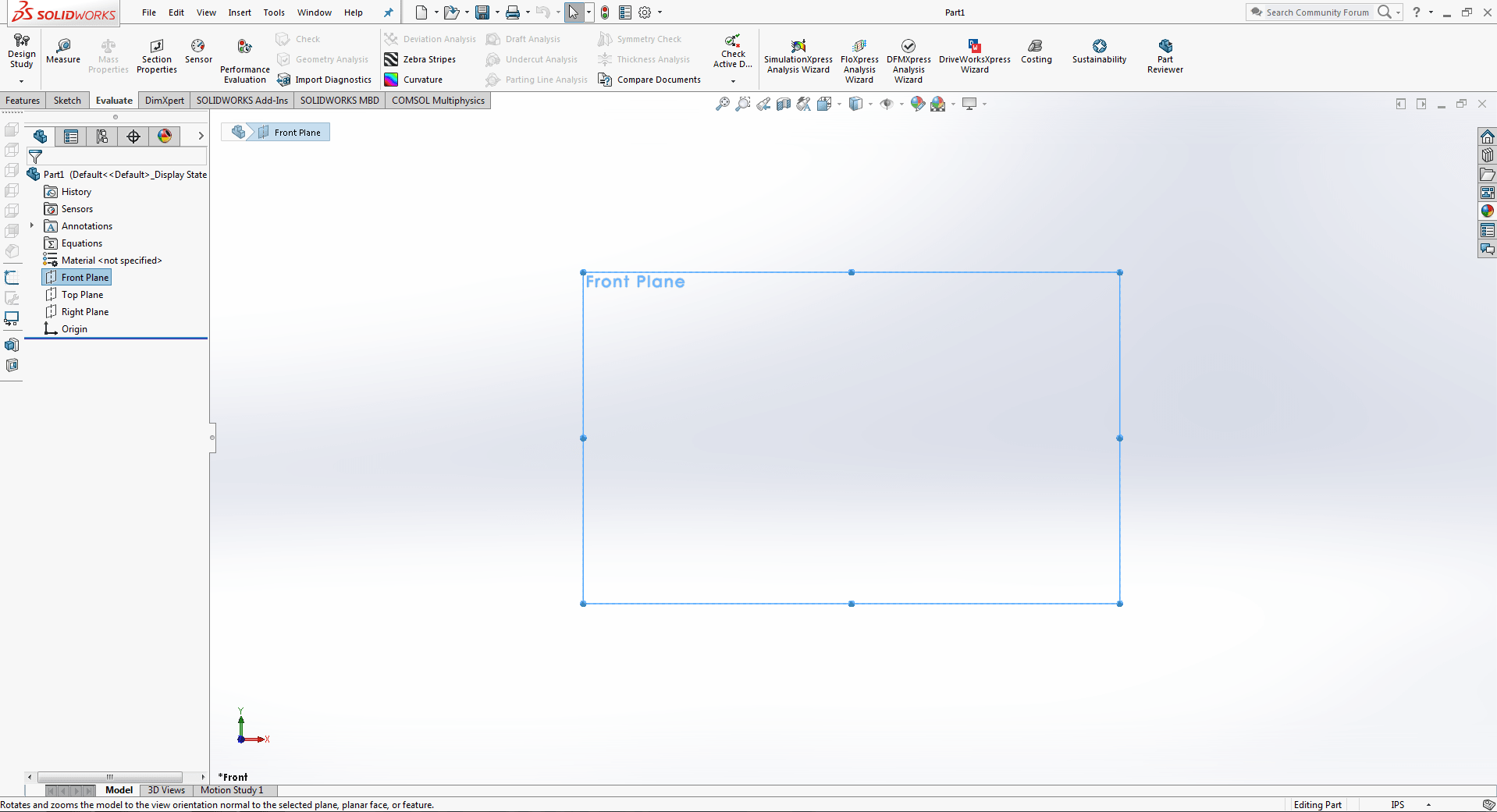
For my design, I've chosen a front layout.
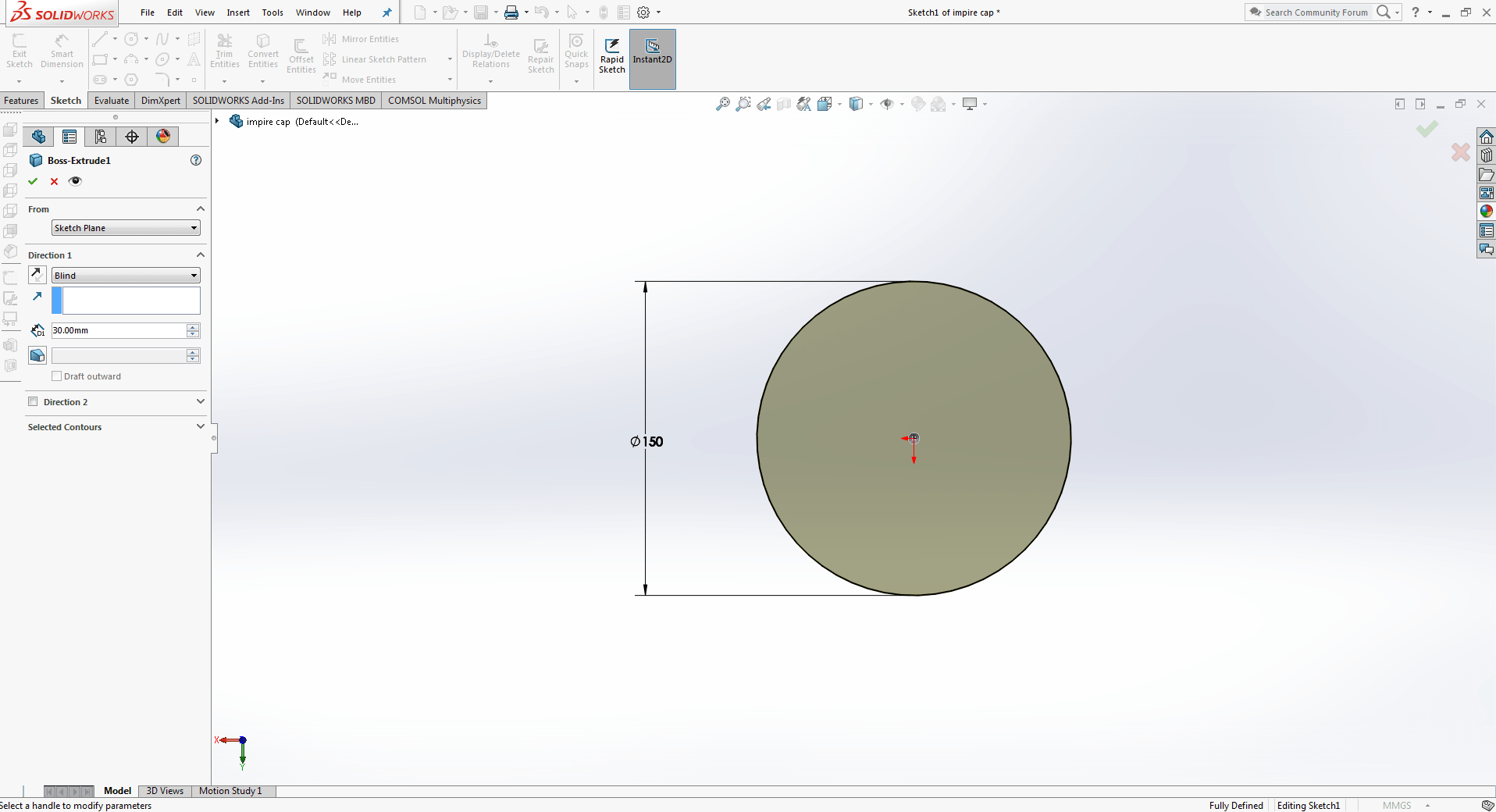
Now I've drawn a 150mm circle then I extrude the circle.
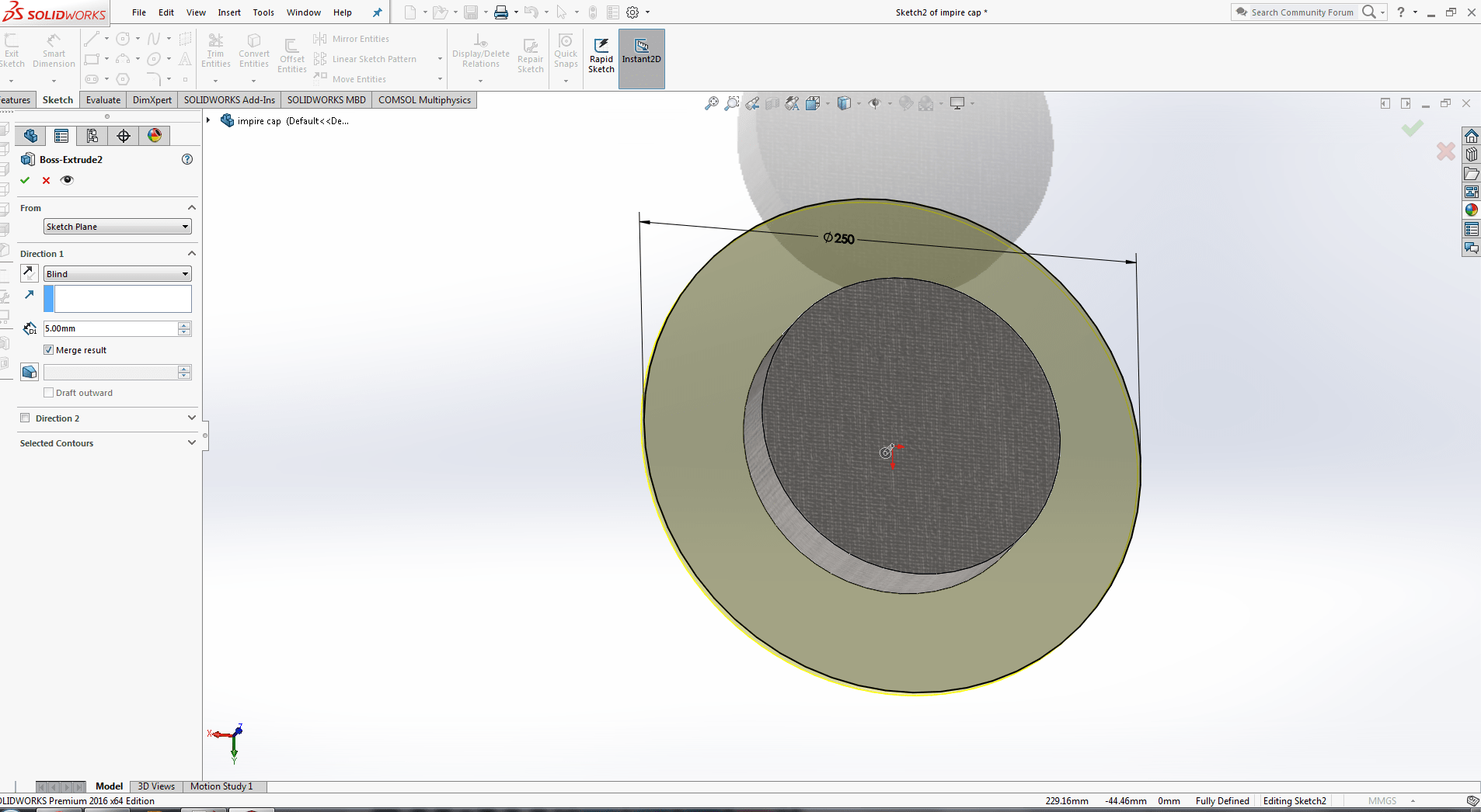
Now that I've drawn a 200mm circle, I'll extrude it.
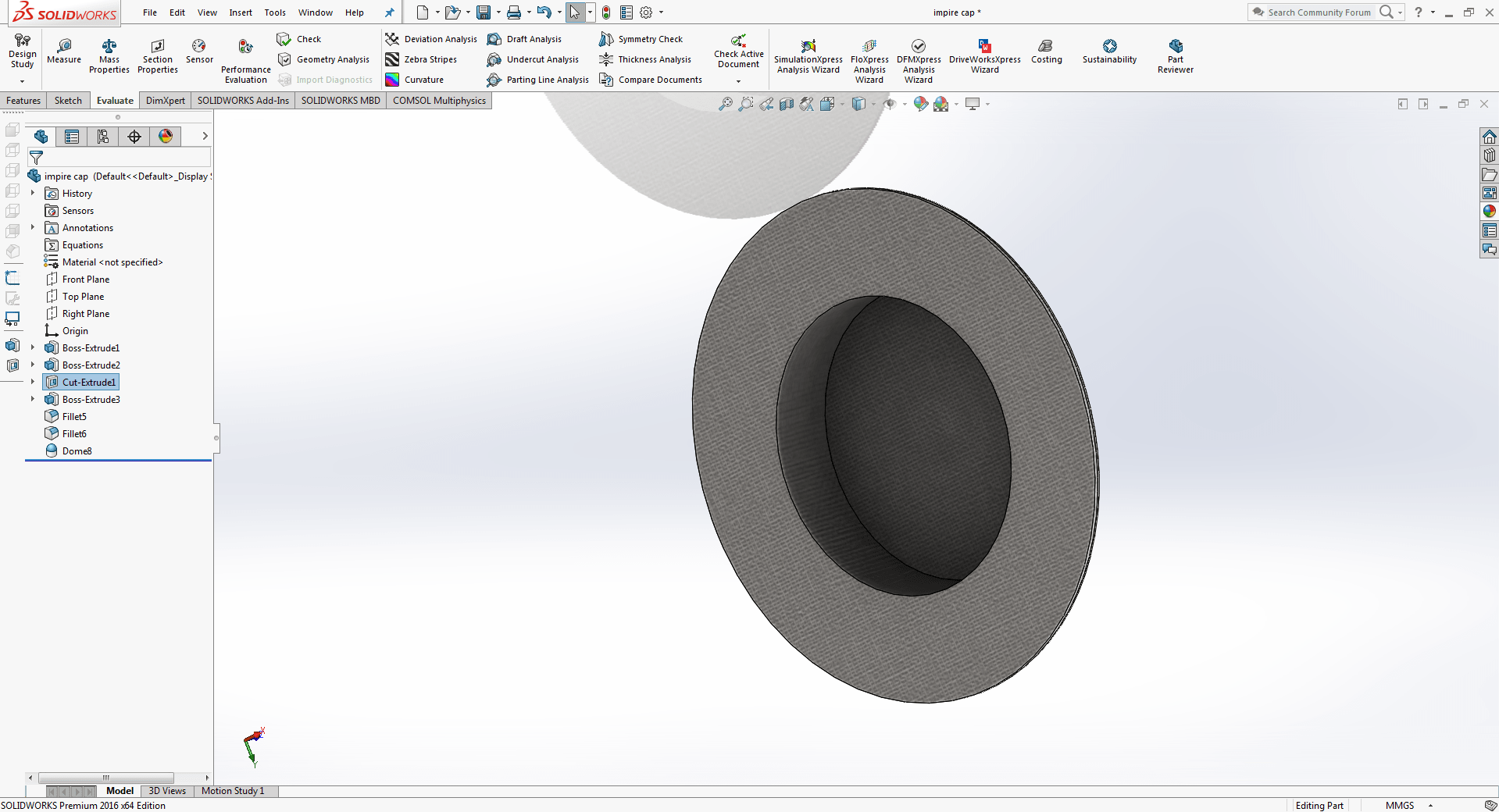
As desired, this is the needed 3d modelling design.

It's now time to fillet the corners.
Vcarve Pro
The ShopBot is like any other CNC machine which we have used previously. It runs on a series of commands which are called G-codes. These codes are like instructions executed line by line, they tell the machine where to move and what to cut. There is a whole host of processes involved in computer controlled cutting, and it all starts with a CAD design. The process of preparing for the cut is similar to other CNC machines, first you need to design what you are going to cut using a designing software like solid work. You can design in your favorite design tool and export as a .DXF file which can be used by Vcarve. Create a new file in VCarve. This will open a window where you can specify the size and thickness of the material to be milled. The white rectangle will update (in ratio) when the width and height numbers change.
Although the width and height do not need to be exact to the millimetre, the thickness must be. As a result, you should use a caliper to measure the material thickness around the edges and try to obtain an acceptable average number. .
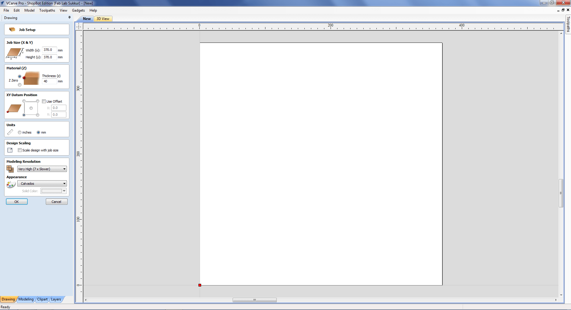
Defining the parameters of the material to be milled
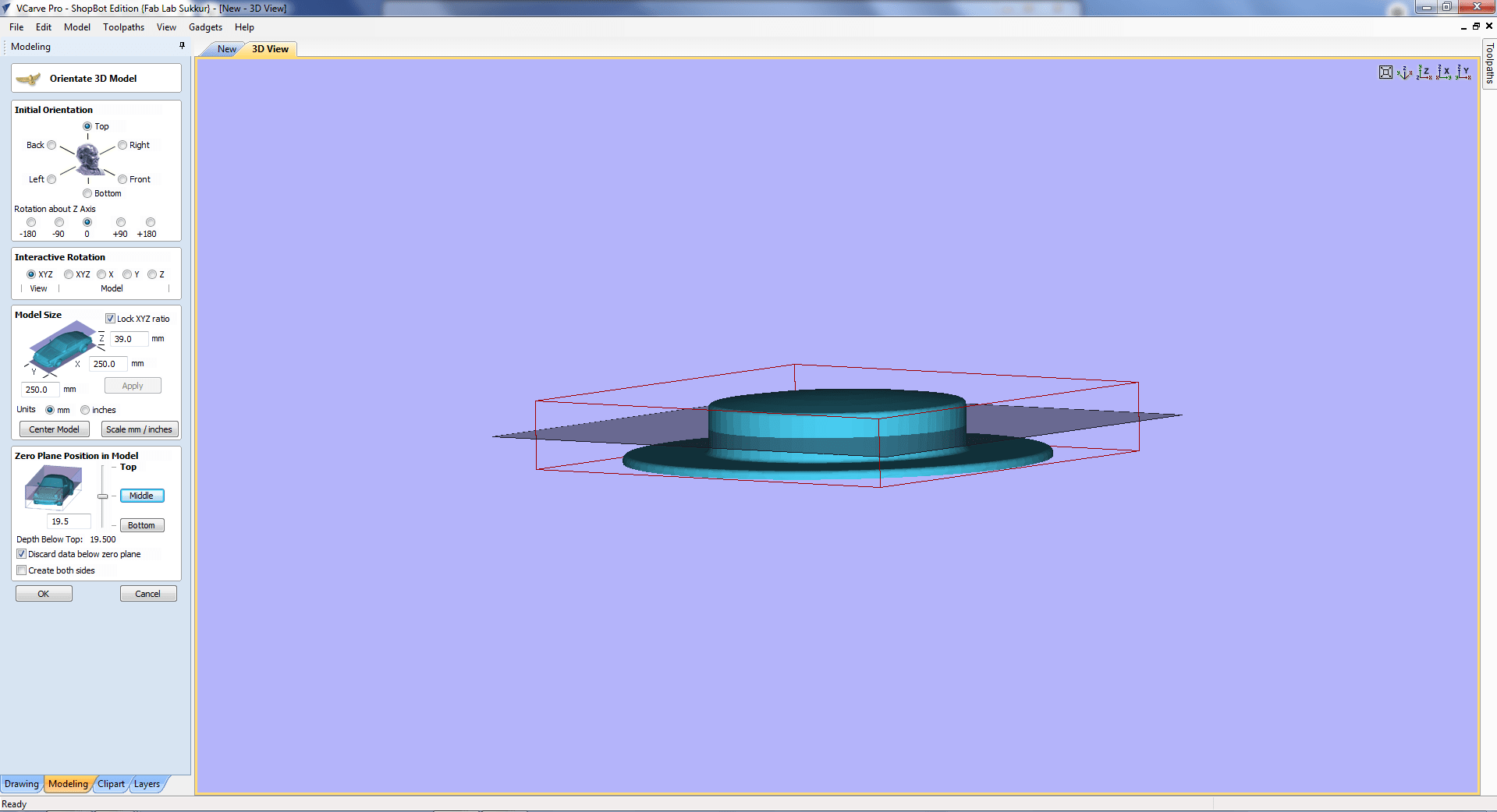
Go to File -> Import -> Import Vectors and load the .dxf file with the design (or another vector file, such as .eps or .pdf). The next step is to nest all parts (arrange) to fit it optimally without wasting material. For that you need to define the orientation , model size, plane position of the model.
In VCarve's Drawing tab, with my umpire cap design loaded
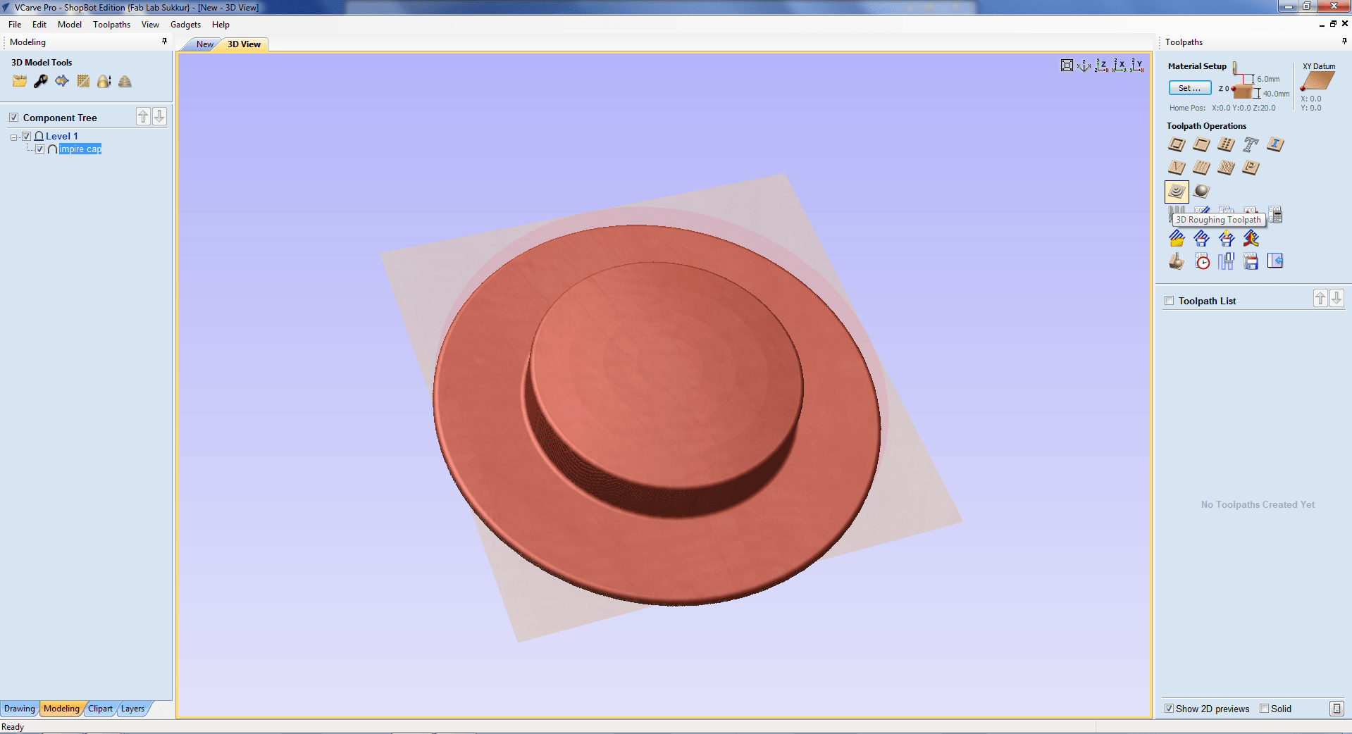
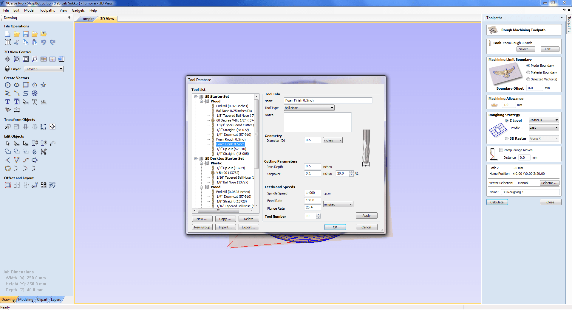
To generate the tool path go to the toothpath window and select 3d roughing tool.
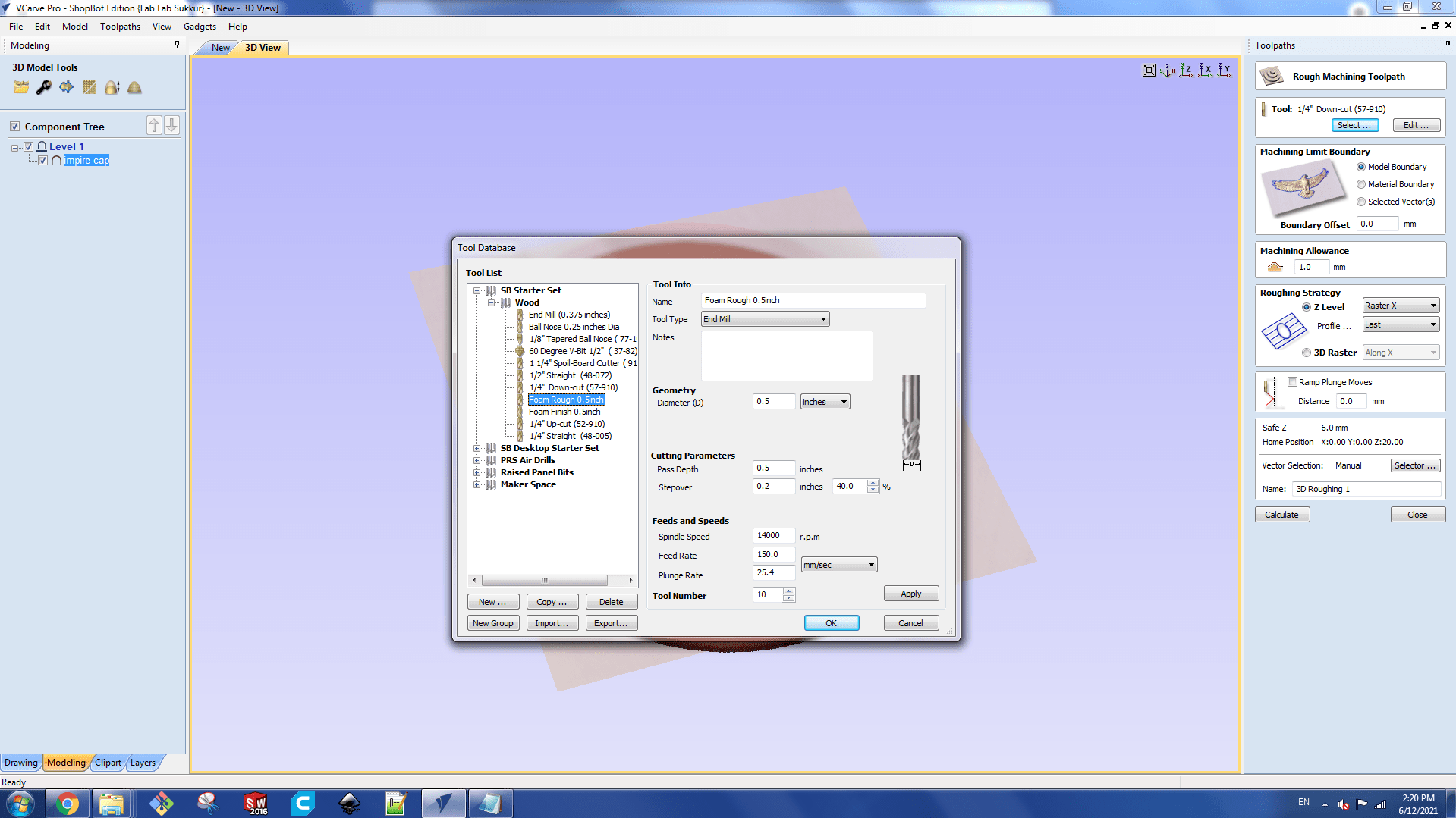
Select Rough Machining Toolpath from the toolpath menu. We're using a 0.5 inch End Mill drill bit.
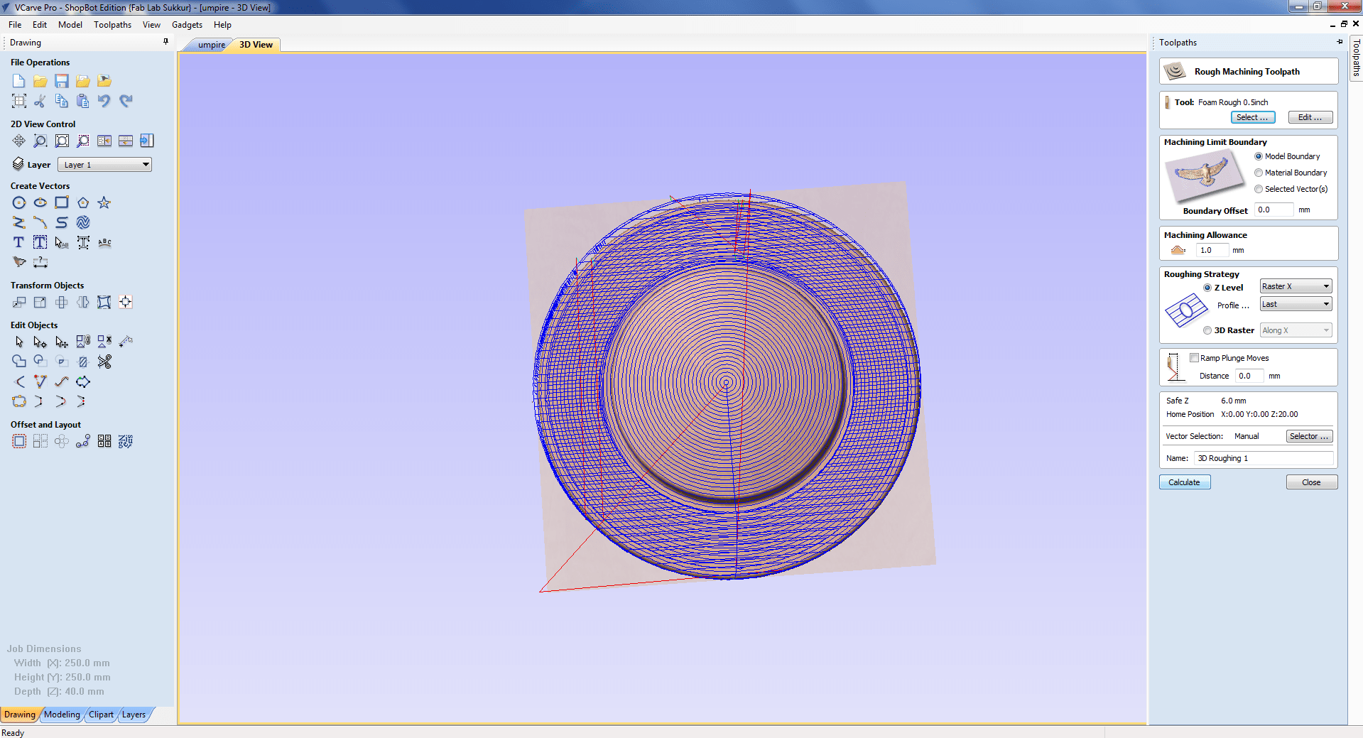
Preview of roughing toolpath
To complete the finishing process, I repeat the same method.
For finishing part we select ball nose 0.5 inch bit
Now my file is ready to calculate gcode file
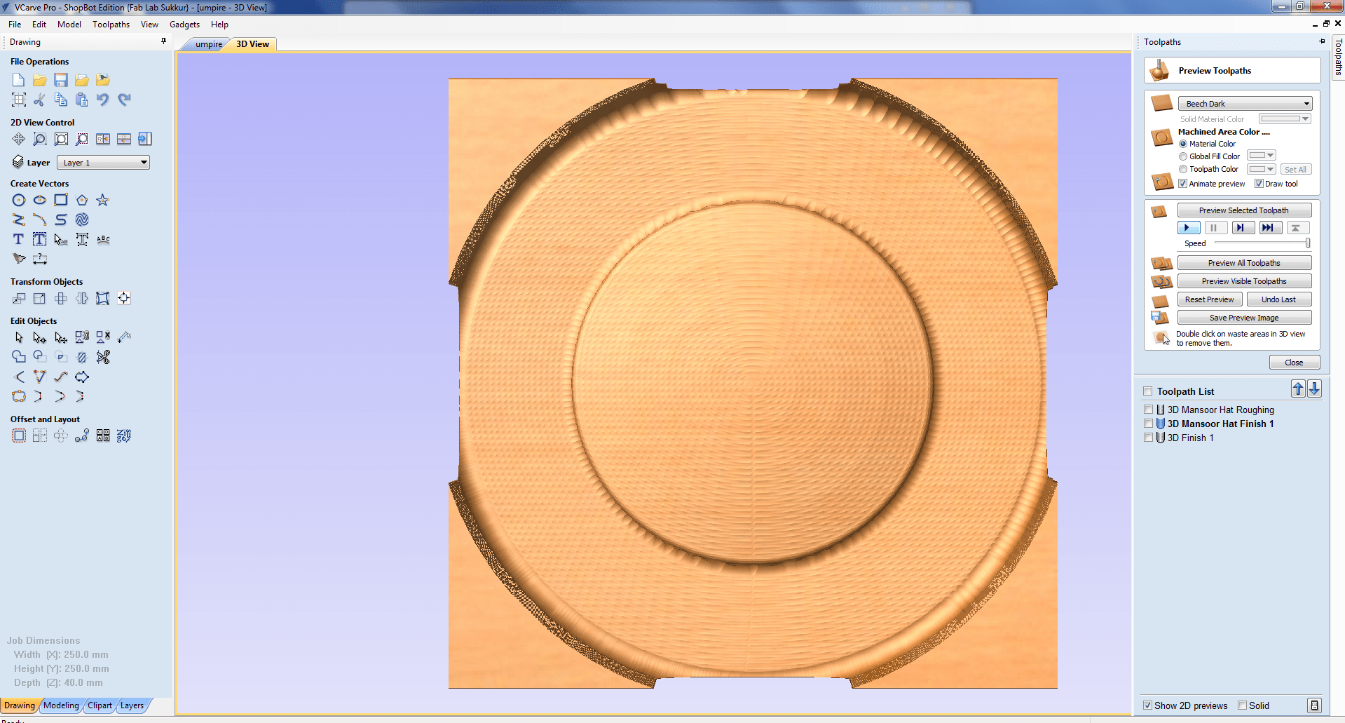
Preview of Finishing
Then I go to Shopbot to cut my job.
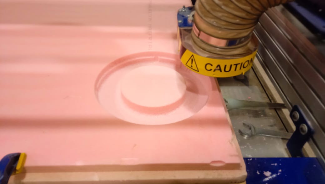
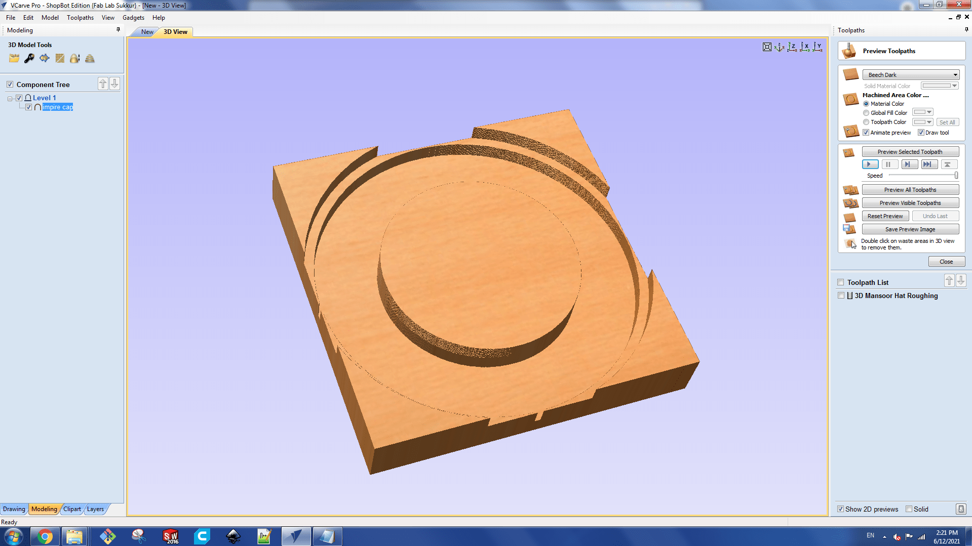
This is the final mold after roughing , finishing and cutting.
After removing mold from the machine its looks like desire result.
Fabric and Composites
In my assignment, I'm using a double layer of fabric, which hardens the surface. The cloth is arranged in such a way that one layer is positioned at a 45-degree angle to the next.
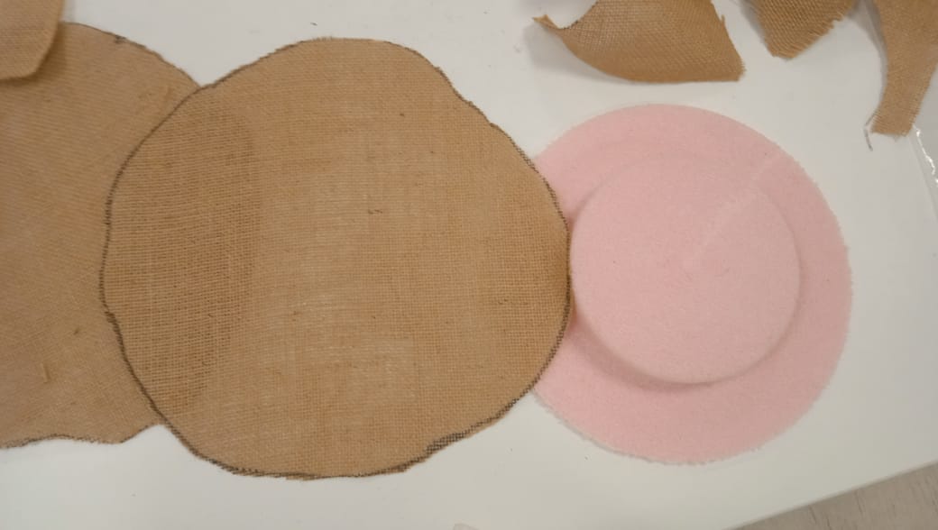
Cutting Fabric of mold size
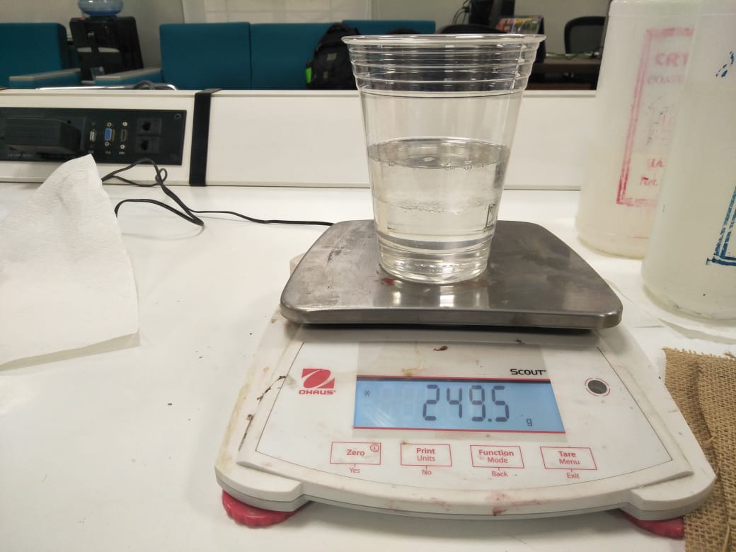
The ratio of Resin and Hardener is mixed in 5:4 and the total quantity is 3xweight of a material which is 249.5gm approximate.
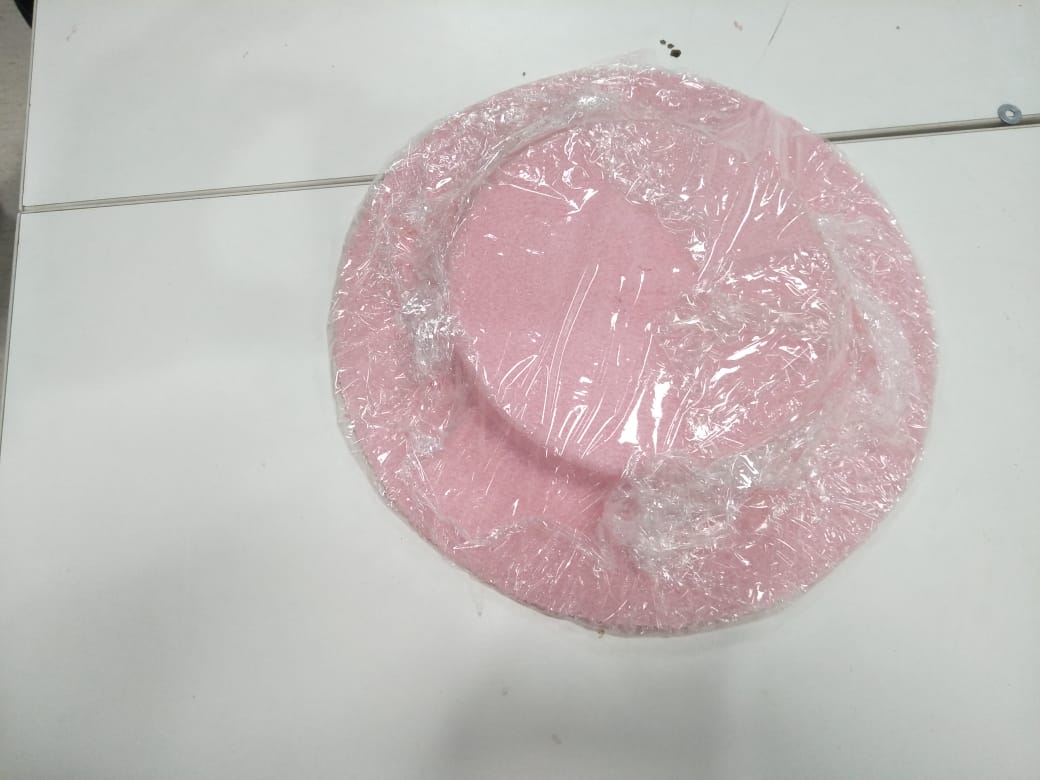
The plastic layer is covered on mold so it safe from Resin and can be use again.
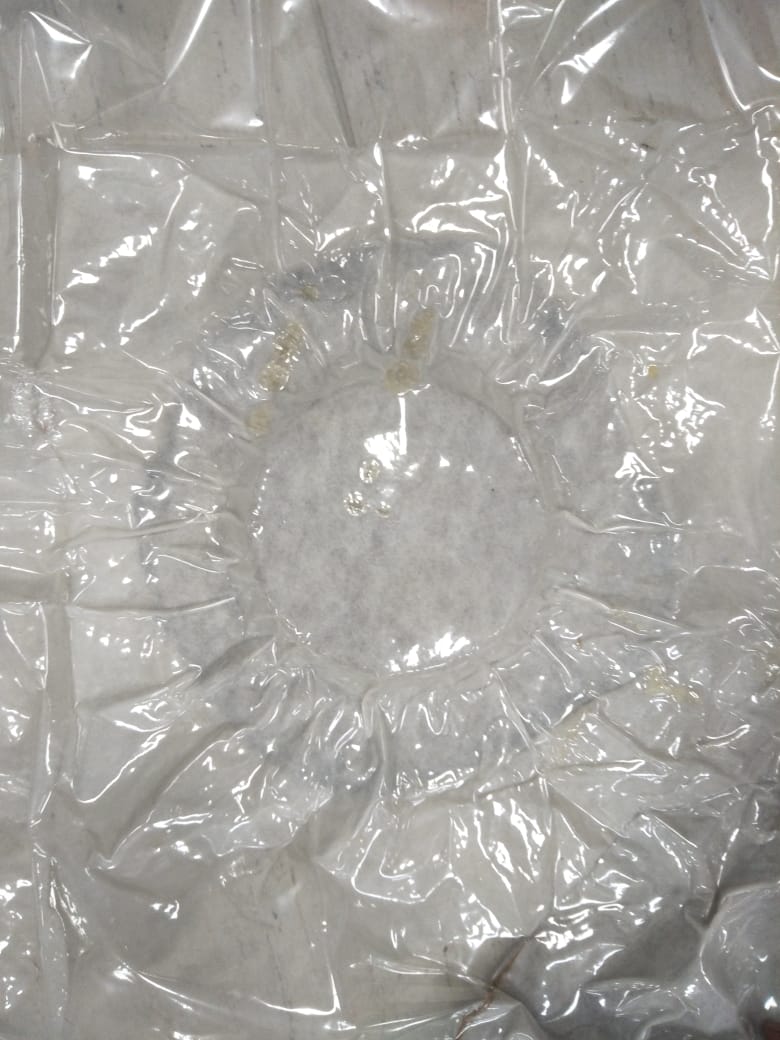
Put the whole experiment into air bag which is used to suck the air and build pressure on composite to attain the shape.
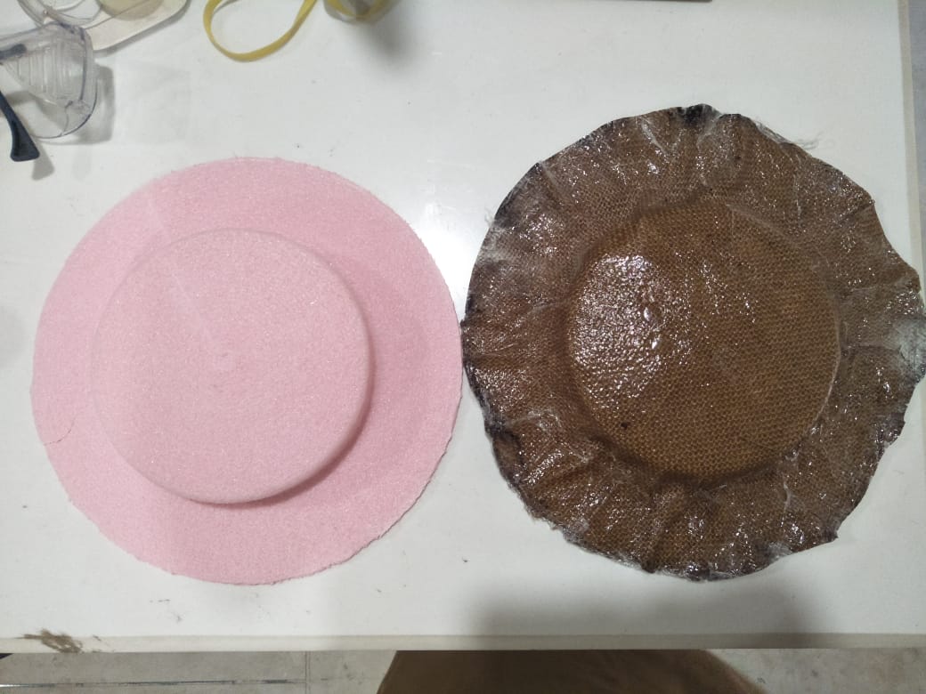
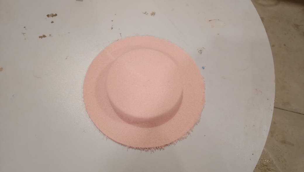
After allowing the material to cure for a day, the end product is like rock-hard.
"Click here"to download all files of this week