Group Assignment
Measure the Power Consumption of an Output Device
In this week group we have planed to measure the power Consumption of the Dc motor
How to measure the power cosumption
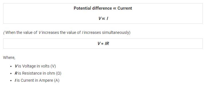
for the calculation of Power , we know that Ohm law , it is stste that "Ohm’s Law states that the current flowing through a conductor is directly proportional to the potential difference applied across its ends, provided the temperature and other physical conditions remain unchanged. Mathematically it can be represented as,"
Power Calculation :
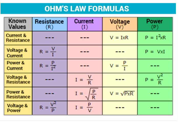
The rate at which energy is converted from the electrical energy of the moving charges to some other form of energy like mechanical energy, heat, magnetic fields or energy stored in electric fields, is known as electric power. The unit of power is watt. The electrical power can be calculated using the Ohm’s law and by substituting the values of voltage, current and resistance. linked HERE
Experiment :
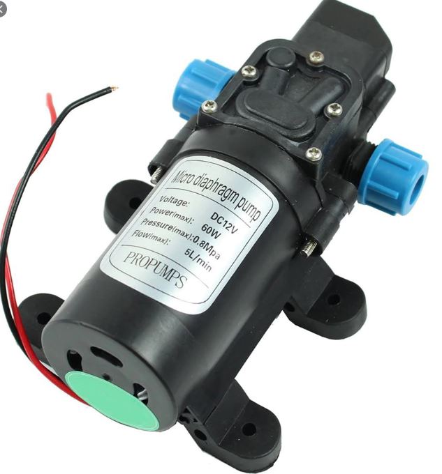
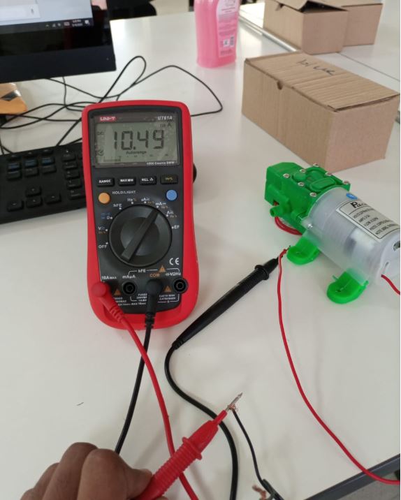
First, we have select the Dc Motor that Working on the 12.0V voltage, After that we have decide that we use the Digital Multimeter to measure the Voltage and Current and used the Power Calculation Formula to Caculate the Power,The DC water Pump Motor Having these Properties.
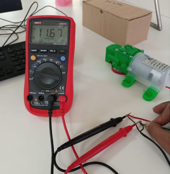
Now Connect Motor With Power Supply and Check the Input Voltage by using the Digital Multimeter, while Motor is Runing state:
After the Voltage Measurement , Now we have Measure the Current , So We have change the connections of Digital meter, for current we have use the meter as Series Connections. in Series connection meter looks like a Ammeter.
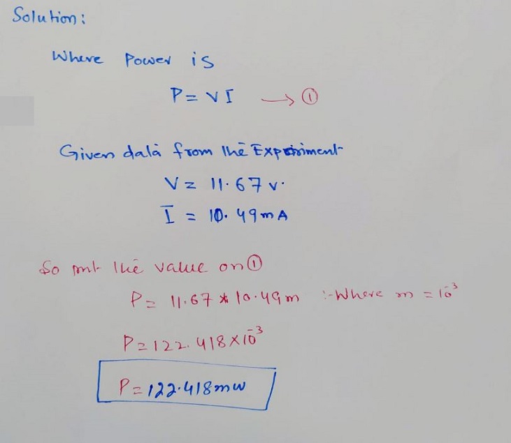
Now using the Voltage and Current we Have Calculate the Power for the Power Formula:
Assignment
Add an output device to a microcontroller board you have designed and program it to do something
In this week, i want to make breakout board of two L293D motor driver IC to control 4 DC motors using microcontroller.
l293D Motor driver IC
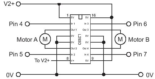
The L293D is a popular 16-Pin Motor Driver IC. As the name suggests it is mainly used to drive motors. A single L293D IC is capable of running two DC motors at the same time; also the direction of these two motors can be controlled independently. So if you have motors which has operating voltage less than 36V and operating current less than 600mA, which are to be controlled by digital circuits like Op-Amp, 555 timers, digital gates or even Micron rollers like Arduino, PIC, ARM etc.. this IC will be the right choice for you.
For further details click here
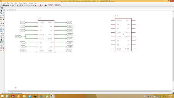
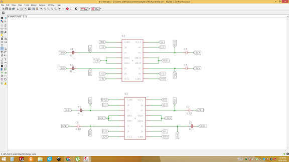
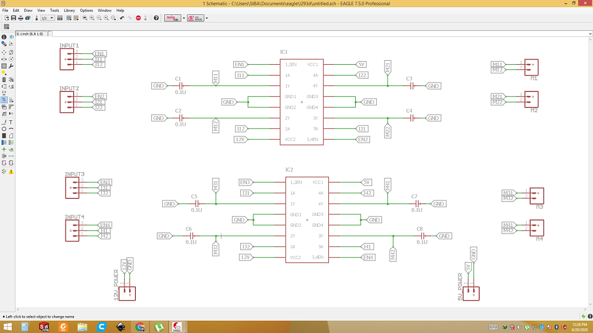
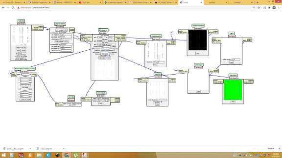
PCB Desiging(Schemtic)
Open eagle software and import 2 the L293D ic. Name it's terminals using label command.Import the connectors and using above diagram connect the wires.
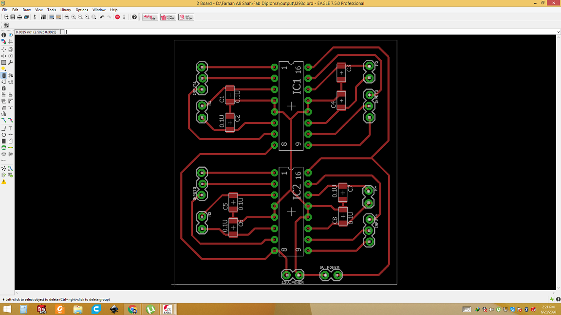
PCB Desiging(Board layout)
Now switch to the board layout and route the wires. After routing select the only top layer and pad then generate image file. Edit the image and generate the seperate file for holes, boarder outline from traces file. Keep dpi 2000 for every image.
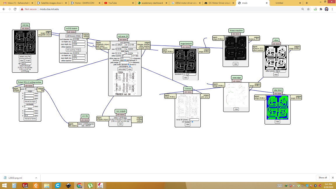
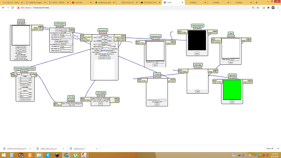
Generate the RML files
Open the mods and upload the trace file. Select the dpi 2000 and tool bit to 1/64 inch. Click calculate. Repeat the same process for outline and holes. Select the tool 1/32inch for holes and outline. Click calculate. RML files is generated.
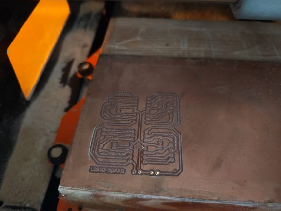
Milling
Open the SRM20 machine software. First replace the tool with 1/64 for traces. Manually set X,Y and Z coordinates of machine. Open the rml file of traces and select output. After job of traces is completed, now replace the tool with 1/32 for holes and outline. Set Z-axis of machine again. Now open the rml file of holes. Then click output. Then open the rml file of outline and click output. Take out the pcb and clean it.
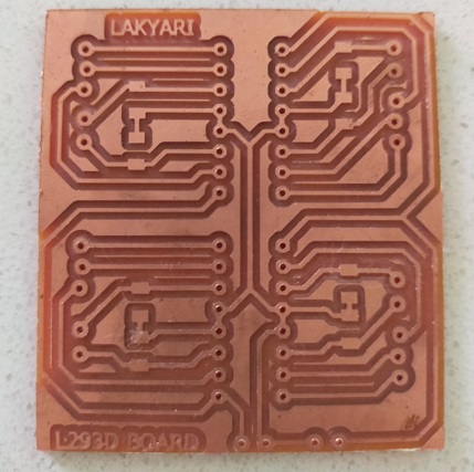
Result
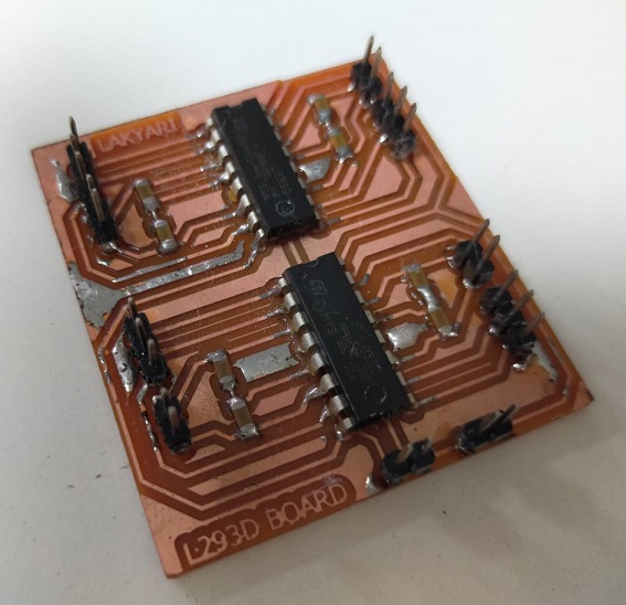
Now solder the IC and other components. After that solder the connectors. Here is final result.
Connect Motor driver with Microcontroller(Atmega32U4)
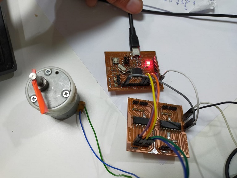
Now connect the Motor driver broad with Atmega 32U4 board which i made in week8(embedded programming). For testing purpose i am using only one motor. I will use this baord in final project where i will drive 4 motors at a time using these boards. 3 signal wires is connected with digital pins(5,10,9) of microcontroller. D5 is enable pin. D10 and D9 are signal pins which controls the direction of motor. Ground to groud. 5v from microcontroller and 12v from external DC supply connected to the motor driver board.
Test Code
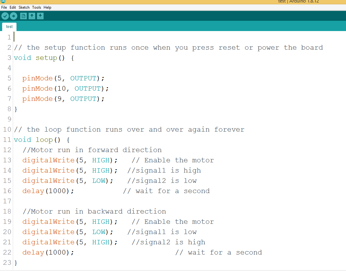
Open arduino IDE and upload simple test code. In this code, i am making enable high, signal 1 high and signal 2 low for 1 sec. This make motor to run in clockwise direction for 1 second. Then making enable high, signal 1 low and signal 2 high. This make motor to run in anti-clockwise direction for 1 second. This loop will go on untill power is on to microcontroller as well as to motor driver.
Final Demo
Test for my final project
After succesfull test on single motor. Now i have connected 4 motors to motor driver board. connect the motor driver to the atmega 32U4 board. Program the microcontroller to run all the four motors in clock wise direction for 1 second and then anti-clockwise direction for 1 second. this loop goes on untill power is connected.
Download all files from here

This work is licensed under a Creative Commons Attribution-NonCommercial-ShareAlike 4.0 International License.