
Assignment
- Read a Microcontroller Data sheet:
- Program your board to do something, with as many different programming languages and programming environments as possible.
Group Assignment : Reading Data sheet and Architectures.
In this Group assignement we have study about data Sheet and Architecture of Micro Controller.
Introduction to AVR Microcontroller
Microcontroller is the advanced version of microprocessors. It contain on chip central processing unit (CPU), Read only memory (ROM), Random access memory (RAM), input/output unit, interrupts controller etc. Therefore a micro controller is used for high speed signal processing operation inside an embedded system. It acts as major component used in designing of an embedded system Click..
Where AVR microcontroller is an electronic chip manufactured by Atmel, which has several advantages over other types of microcontroller. We can understand microcontroller by comparing it with Personal Computer (PC), which has a motherboard inside it. In that motherboard a microprocessor (AMD, Intel chips) is used that provides the intelligence, EEPROM and RAM memories for interfacing to the system like serial ports, display interfaces and disk drivers. A microcontroller has all or most of these features built into a single chip, therefore it doesn’t require a motherboard and any other components, Click.
AVR microcontroller comes in different configuration, some designed using surface mounting and some designed using whole mounting. It is available with 8-pins to 100-pins, any microcontroller with 64-pin or over is surface mount only. Click.
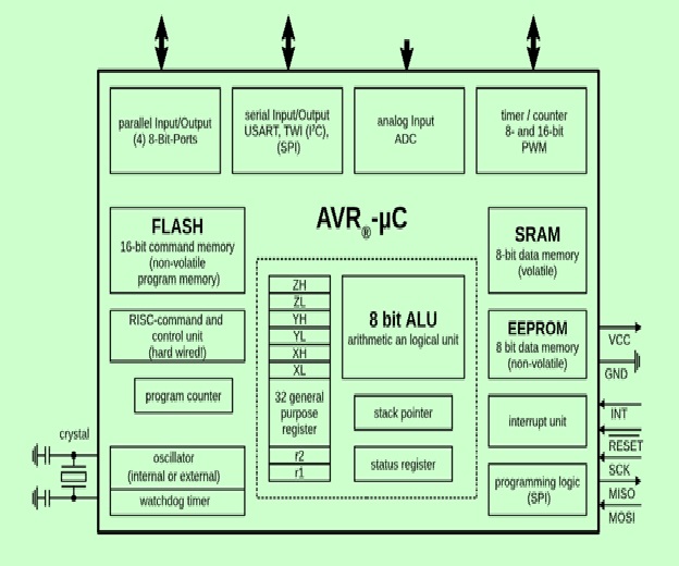
CPU: The CPU has an 8 bit ALU with status register, stack pointer, and 32 general purpose register. 8 GPR can be used as 16 bit register; 3 of the double register as address pointer (X, Y, Z). The GPR are part of the SRAM and thus volatile, meaning they lose their content without power, and are not defined when power returns.
Control Unit: The RISC command and control unit with program counter can treat most 16 bit commmands (instructions) in one clock cycle. We reach near 16 million instructions per second ([MIPS]) Instructionspersecond#Millionsofinstructionspersecond_(MIPS)) with a 16 MHz crystal (about the speed of an INTEL 80386 in 1990). Click.
Input/Output: Depending on the controller we get from one to four 8-bit GPIO ports, 8- and 16-bit timer/counter, a real time clock (RTC), PWM outputs, external interrupts, serial interfaces (EIA232, I²C(TWI), SPI), analog to digital converter (ADC), USB.
Memory: Three memory blocks are available. Non-volatile 16-bit Flash program memory, a little non-volatile 8-bit EEPROM an the volatile 8-bit SRAM. We will look in detail at these memories in this chapter , Click..
Programming logic: The controller memory (FLASH, EEPROM, fuse and lock-bits) can be programmed and cleared over SPI (Serial Peripheral Interface) in-system (ISP), Click.
AVR's are available in many different housings, and can use voltages from 1.8 V to 5.5 V. Apart from ISP they can be programmed using bootloader (Arduino) or debugged over JTAG.
Special Microcontroller Features:
For more details about the AVR Micro Controller use this Link.
PIC Micro Controller
PIC is a Peripheral Interface Microcontroller which was developed in the year 1993 by the General Instruments Microcontrollers. It is controlled by software and programmed in such a way that it performs different tasks and controls a generation line. PIC microcontrollers are used in different new applications such as smartphones, audio accessories, and advanced medical devices.There are many PICs available in the market ranging from PIC16F84 to PIC16C84. These types of PICs are affordable flash PICs. Microchip has recently introduced flash chips with different types, such as 16F628, 16F877, and 18F452.PIC mirco Controller list is, HERE
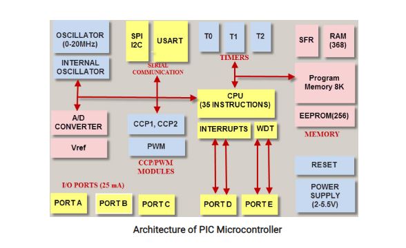
PIC Microcontrollers Architecture.
The PIC microcontroller is based on RISC architecture. Its memory architecture follows the Harvard pattern of separate memories for program and data, with separate buses.for the data Sheets Click HERE
Details for the PIC , Architecture.
Advantages of PIC Microcontroller:
Disadvantages of PIC Microcontroller:
Assisgnments Work :
In this week I have study about the Data sheet and its a very important document of any electronic device/components as it contains all the information we need while using it. In case of micro controller no other documents helps to understand it. Simply its free and authentic source of imformation regarding a device/component Click. Before going to selecting a micro controller for any project we need to know the following things.
- First Find the Range of operating voltage.
- Second find the Speed: What is the highest speed a microcontroller supports?
- Third Find the Packaging: Is it DIP (dual inline package) or a QFP (quad flat package) or some other type?
- Fourth find the Power Consumption: Critical for battery powered products.
- Fifith is The amount of RAM and ROM on chip
- last task is The number of timers and I/O pins on chip
Important of Miro Controller
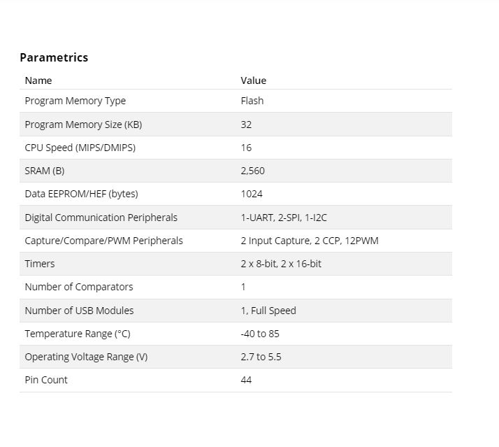
And Data sheet is the place where you can find the details of all above things of a microcontroller, The first think to read from data sheet is the specification of the microcontroller. I read the data sheet of ATtiny24/44/84A and ATmega32u4.I used to design the Embedded Board by using the ATMEGA32U4,Click.
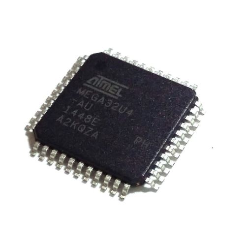
This is use full Tutorail for the Atmega32u4. HERE All detalis are given this link about the Micro Controller,These are the main features of the Proposed MicroController ATmega32U4,For more detail Visit HERE HERE
this is the Pin Daigram of the ATmega32U4.

Now I am going to design the PCB Board in the Eagle Software.by using the ATMEGA32u4 to make Board
This the Eagle Sofware where I have select the Mirco Controler
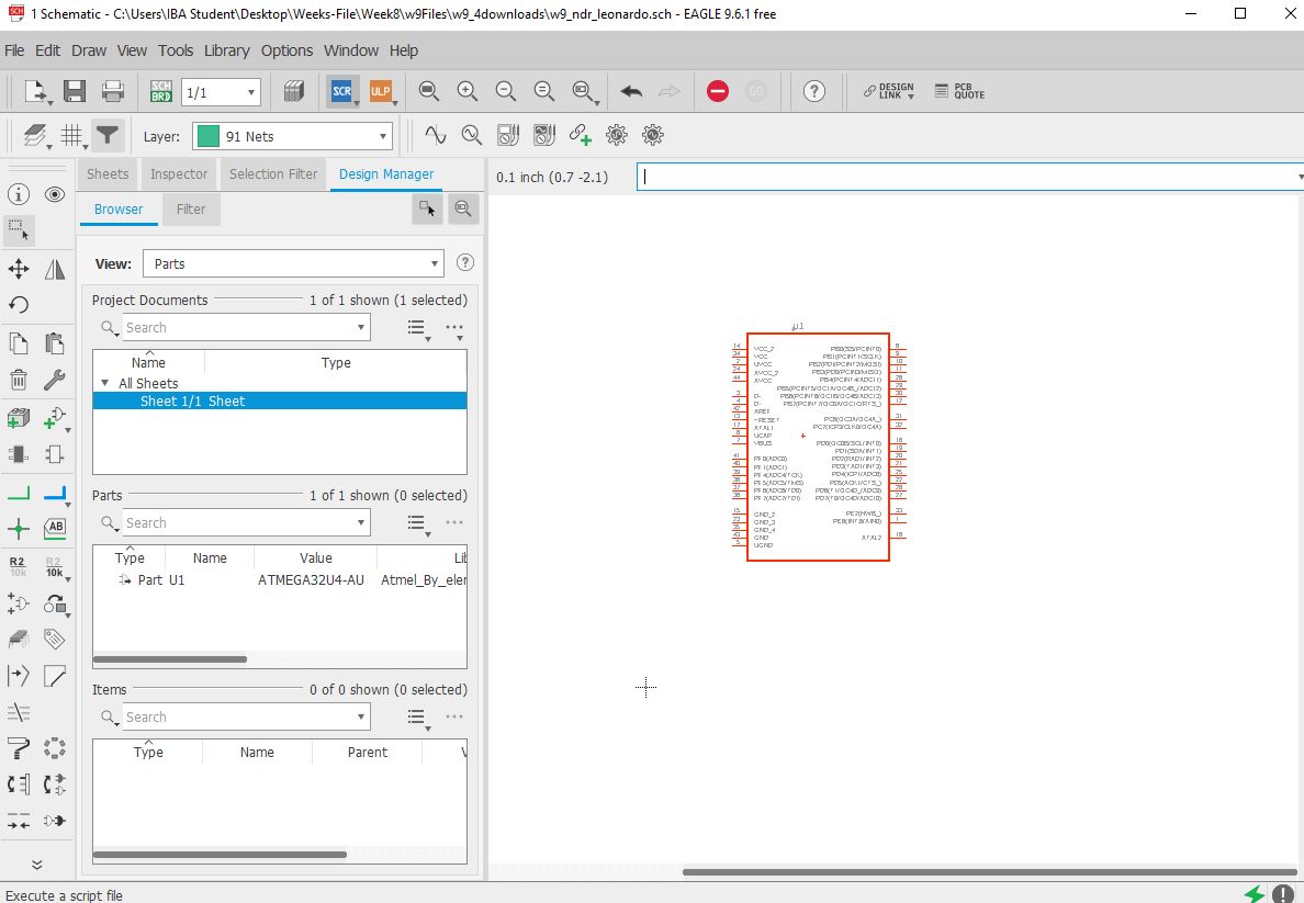
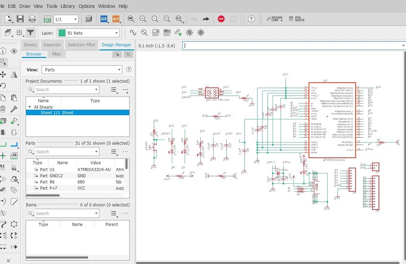
Micro Controller Circuit in Eagle Software.
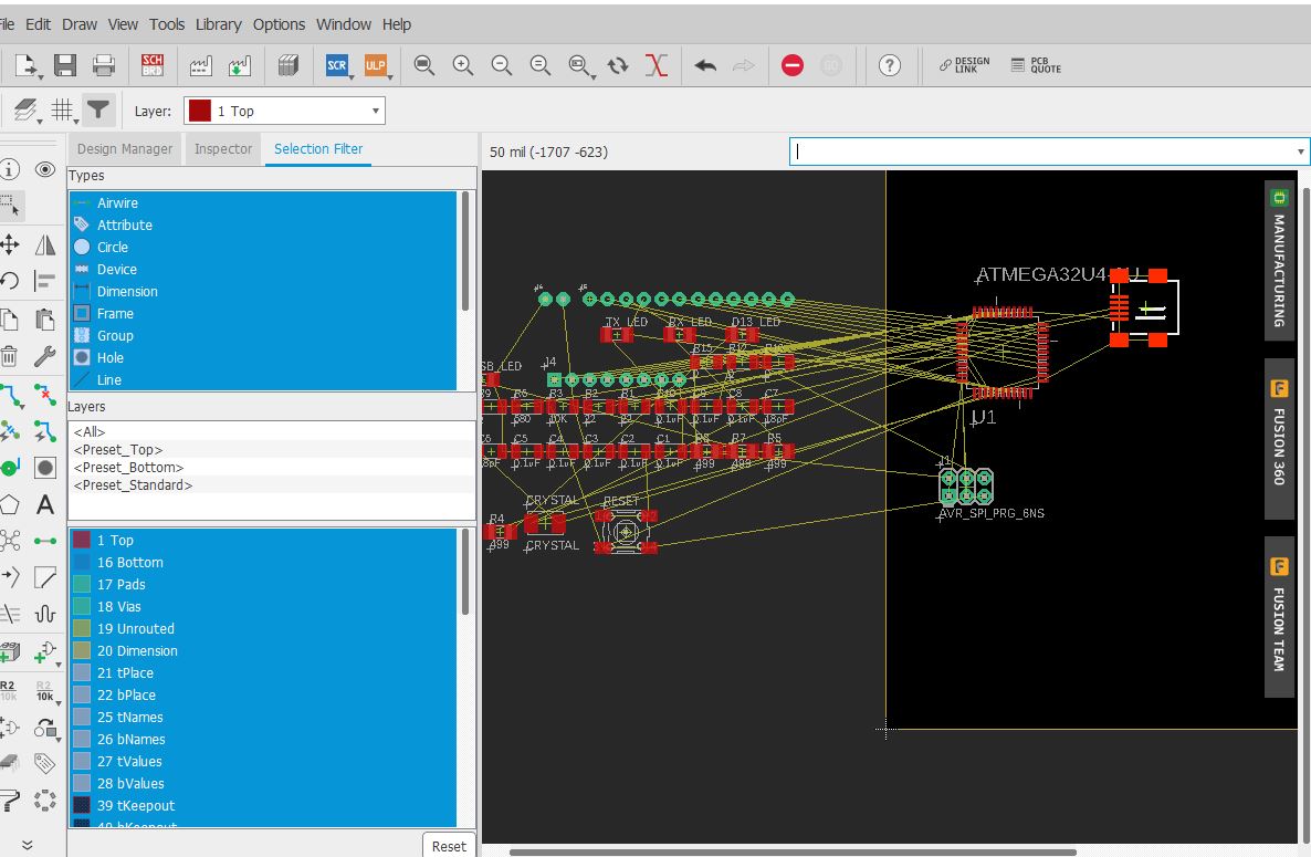
This is the placing of the Components to design the PCB Board
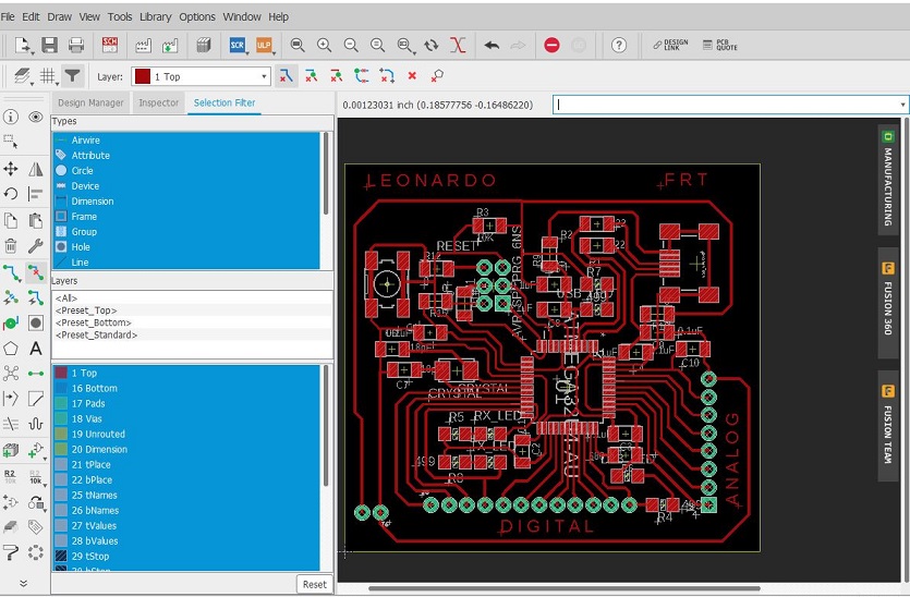
This the final placing of the PCB Board

After the Final Routing of PCB Board :
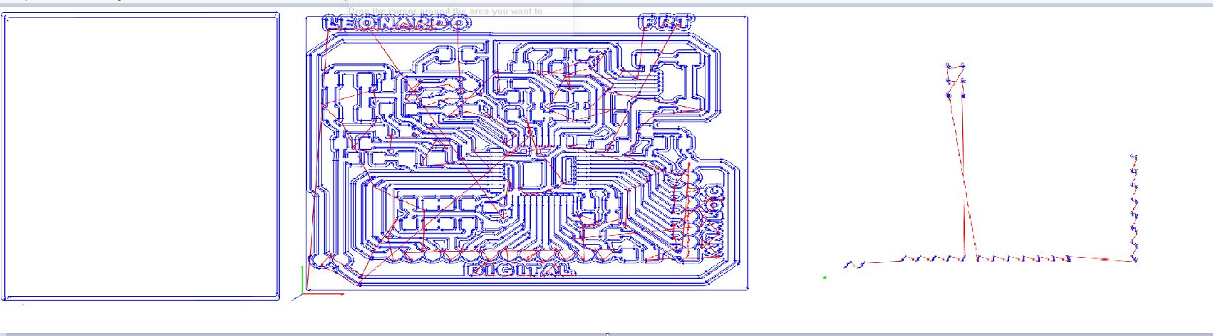
Now I am going to Generate the PNG image for the Milling

This the PNG File , with three others files like an Outer, drill and Trace of the Milling file:

RML code Generated using the Mods

Now the same prcoess apply for the remaining others RML codes just change of the tool bit of 1/32 , like a Outer and Drill.
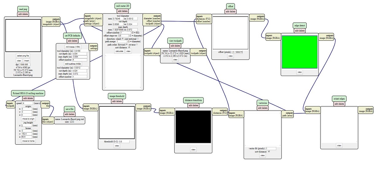
RMLcode form the mods:
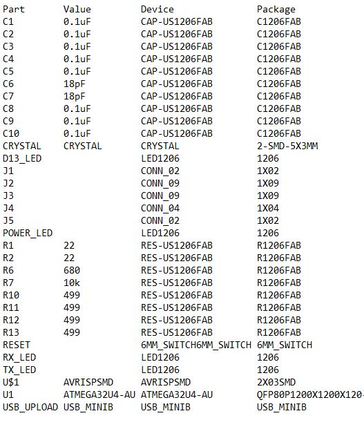
Required the Bill of Material
The Processing of the Milling
All prcoess are same as we have apply on the electronics prodcutaion and Electronics design Weeks.
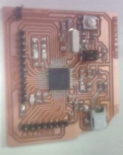
This the Board of At32U4 after the milling process

Now the Soldering the At32U4 Board and after the Soldering.
Final Process Is the Programing
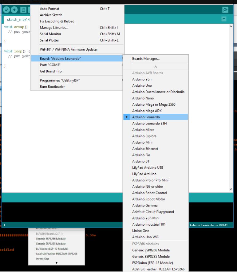
For the Programing I used the Ardiuno ID, First update the Library and boot load the Programmer. Go to the Tools and Select the Board Leonardo.
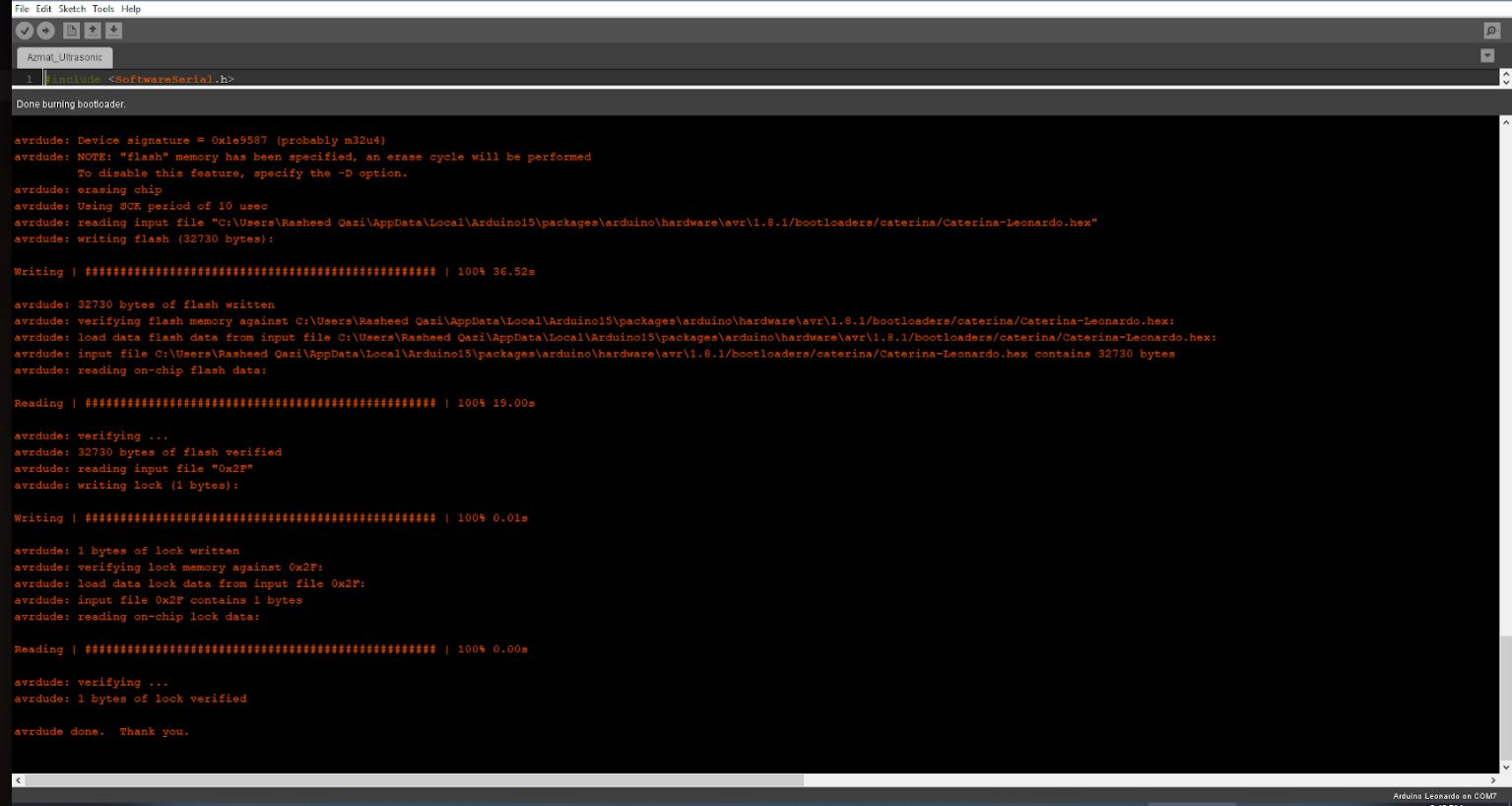
Now boot load the Leonardo Board and Successfully its boot load the Leonardo.
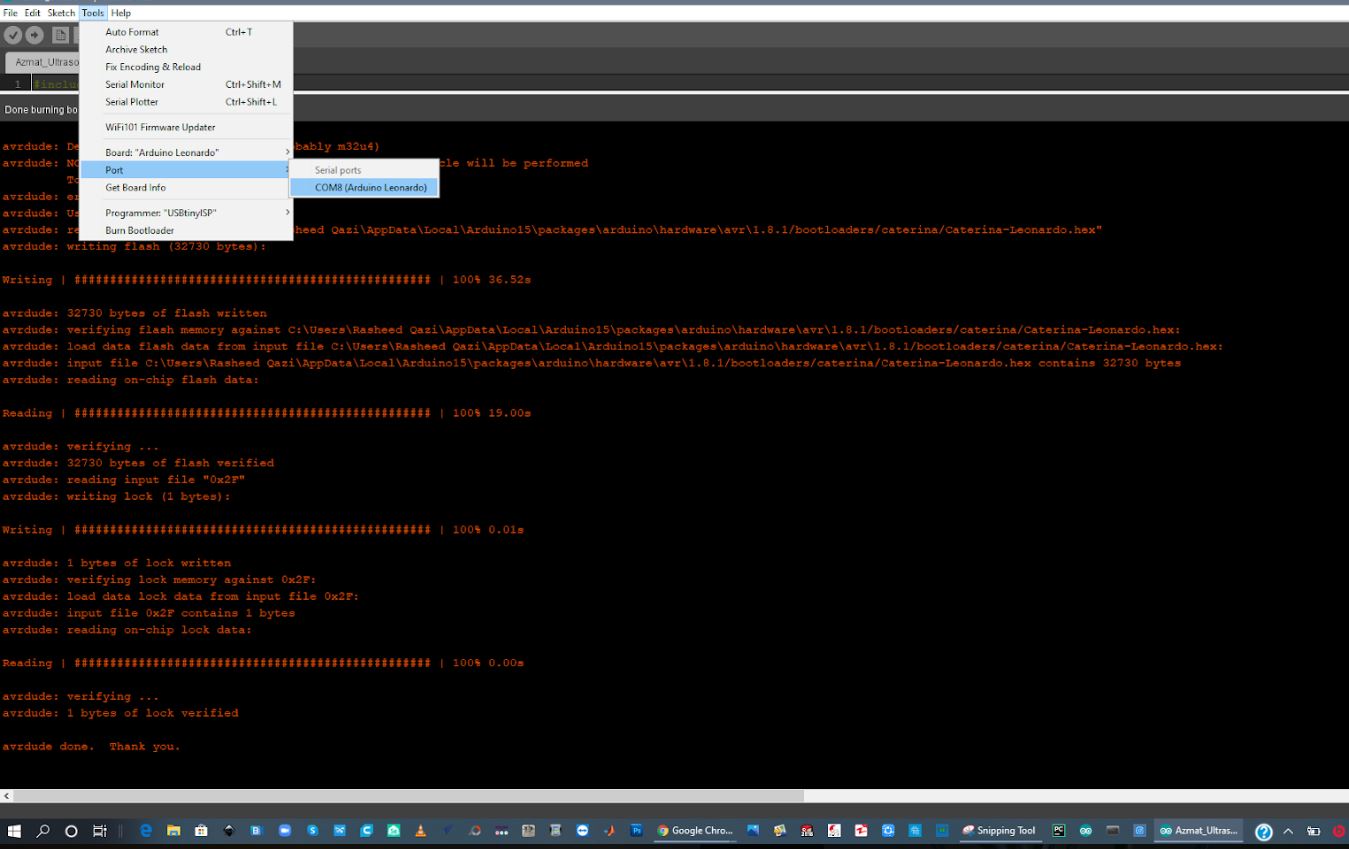
After the boot load, Now I want to check the Port, And its find that its working
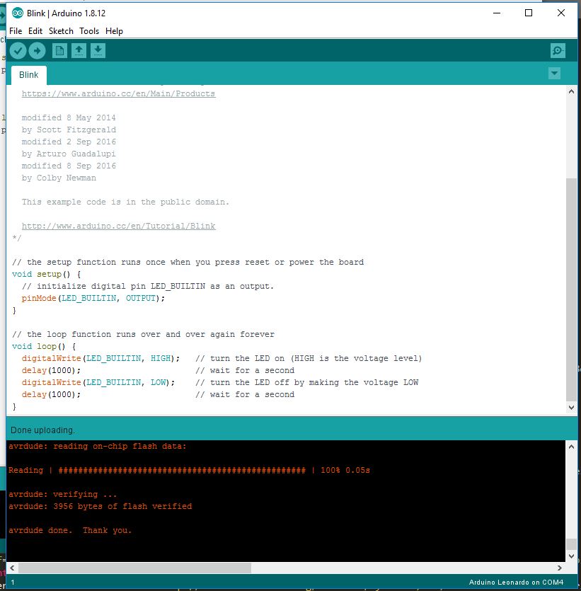
Now this result Show that Leonardo Board is Working,. First I have test the Blink code check that its working.
This is the hardware section which show that Leonardo Board is Blinking
Conclusion
In this Week, I have Design the ATmega32U4 Embedded Board, I also program it and check it that its working, so this week was very Interesting for the PCB design and Embedded Programming.I have used the C++ langauge to program the Board. and I have upload the basic blinkg Code in my Board and found that its working. furthermore I will use this board in Input and output weeks. further more I will used this board in next week.

This work is licensed under a Creative Commons Attribution-NonCommercial-ShareAlike 4.0 International License