
Assignment
Make something big.
GROUP ASSIGNMENT:
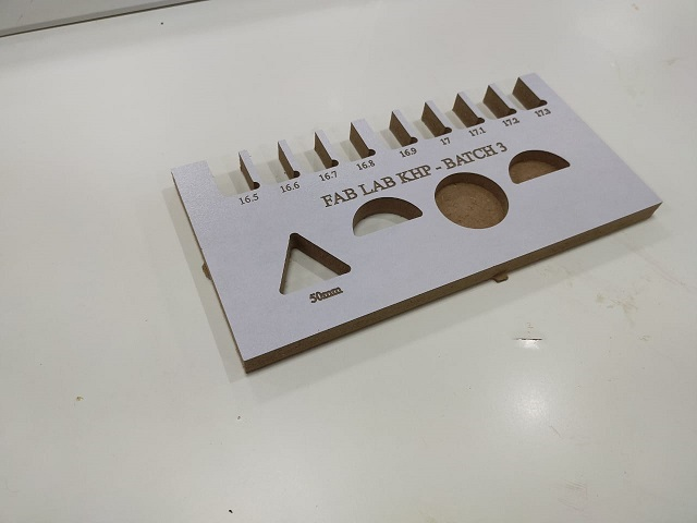
TEST RUNOUT,ALIGNMENT, SPEEDS, AND TOOLPARTHS FOR YOUR MACHINES.MAKING TEST CARD FOR PRESS FIT AND DIFFERENT SHAPES
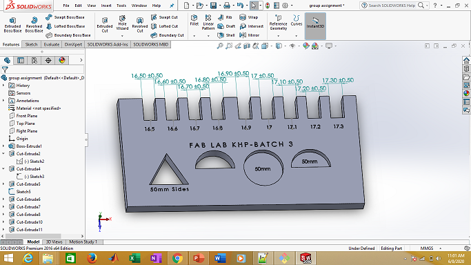
DESIGN IN SOLIDWORKS
We design in solidworks. We put 0.5mm differerce in each slot. We made circle(half and full cut) of 50mm diameter. Triangle of each side equal to 50mm.
In order to cut on shopboat, we need 2D file. So open file and select "make drawing from part".
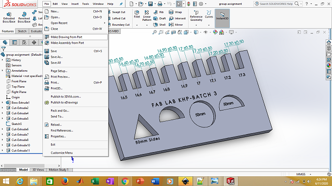
Select the top view and drag it to the main area. then save as .DXF file.
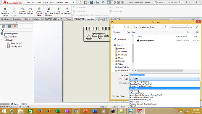
.DXF file in then open in Vcarve and process it.
Make something big.
Individual Assignment
This assignment is all about to make something big. So, I decided to make round table. I started with different ideas like stool, chair, shelf etc. after thta I finalize the round table. I draw rough sketch of table on paper with dimensions. Skteching on the paper is very useful and important for designing. I am use 16mm MDF for this job.
3D Designing
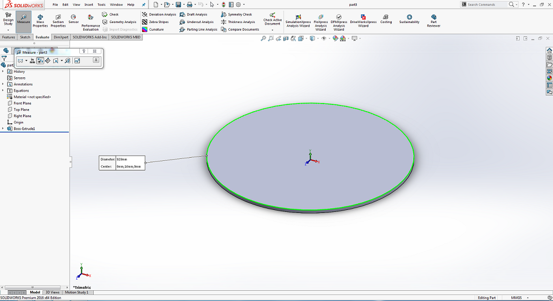
I started designing parts in SolidWorks, First I designed top part of round table. First, I have open the Software and goes to file and open the new file, and Start the design, I have drawn the circle with radius of 920.00 mm and Extrude it with 16.00 mm.
Then I designed Base of table and extrude it.
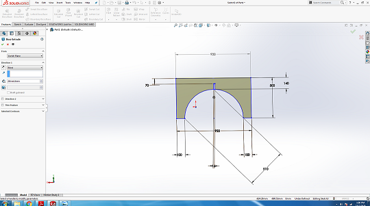
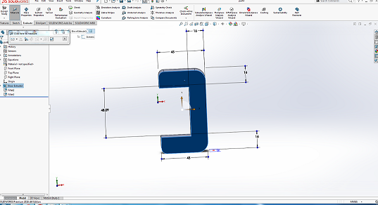
After that I designed supports of table and extrude it.
After the design of all files , Now I am going to assemble all parts using "Mate" to check either the parts fitted perfectly or not.

Uisng " mate" assemble the part of table .
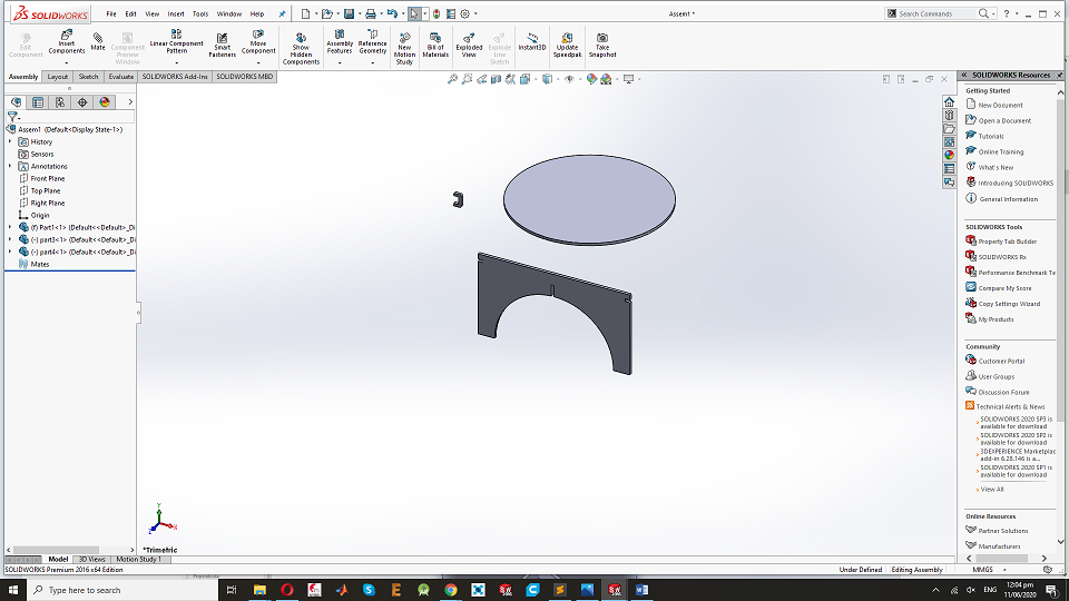
assemble the part of table:
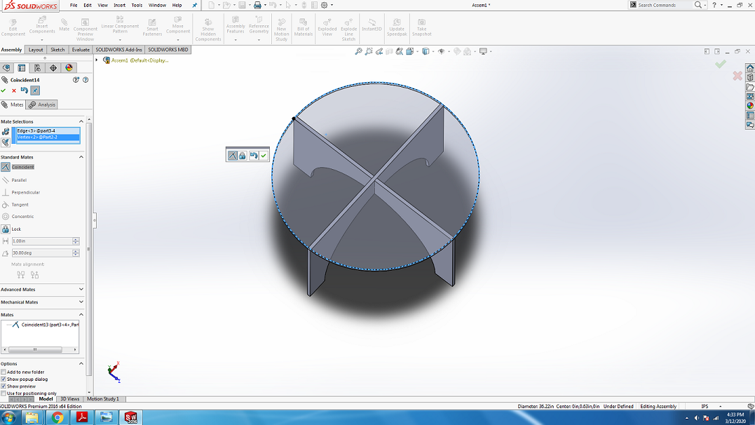
During the "assemble" I found that I did fault in design so , I designed the Support and fixed the base and top of the table.

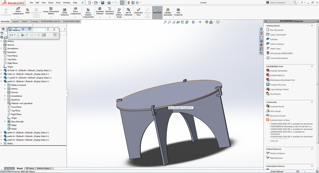
After Asemble all parts of table and It looks like that.
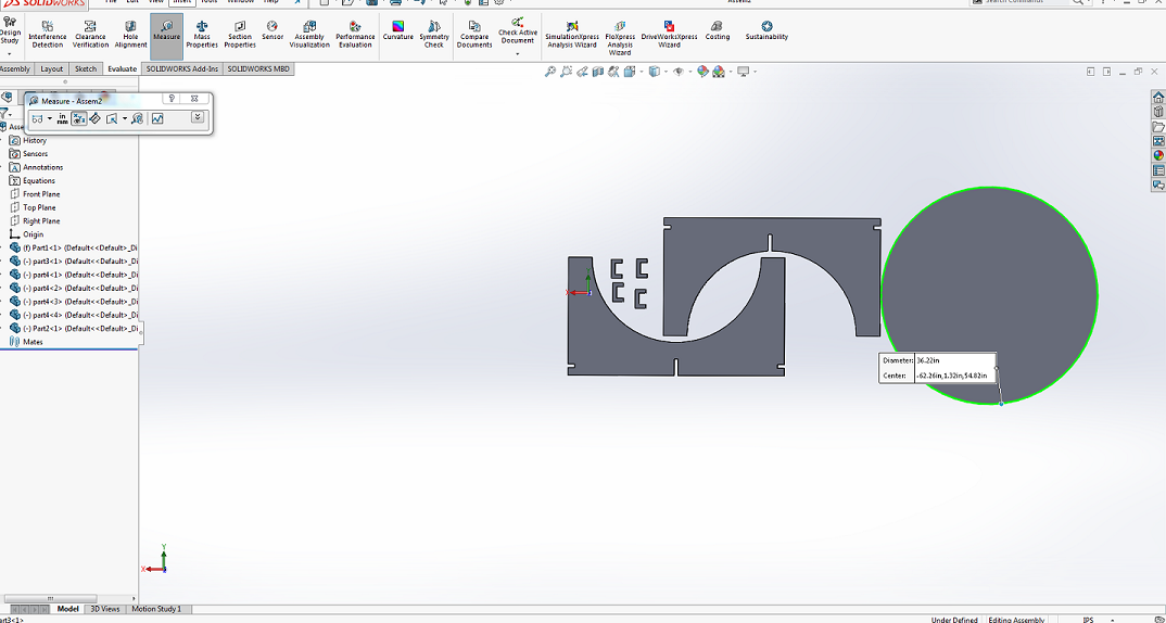
After checking the parts perfectly fitted in assembly I need to make 2D Design for laser cut of it, for 2D Design we open one more assemble tab and set all the parts in front plane.
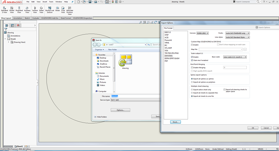
After completing this Processing,Now to save the file in drawing document and save as .DXF format for working in InkScape.
The generated .DXF file is opened in InkScape and scaled to 25 percent of original size, this can set slit parts to 4mm thick material as we use 4mm cardboard to try a sample for this design. after that we have generated the .pdf,first design for laser cutting process in Epilog Laser Cutting machine.

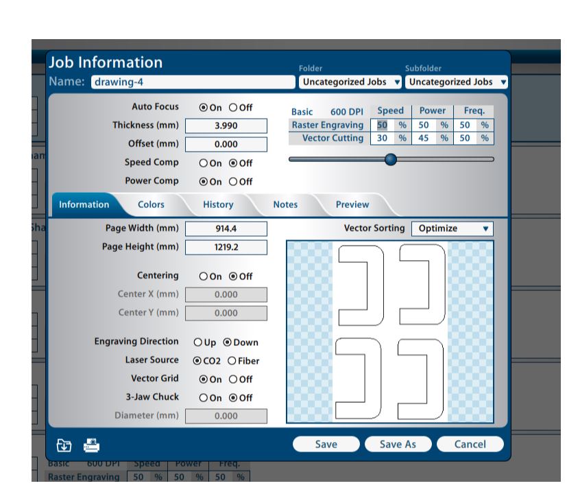
Now .pdf file open and set in Epilog Job Management Software,I used 75Watt Epilog M2 Fusion laser Cutting Machine for the Cutting.
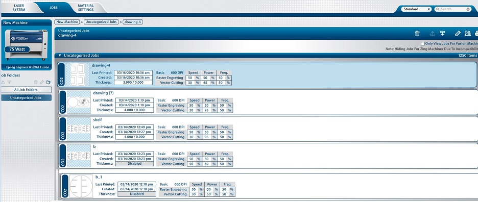
This is the procdure to cut the Job in Eplog Machine.
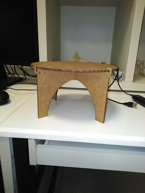
After the scaled design on 4mm cardboard , this is the Final Look of table.
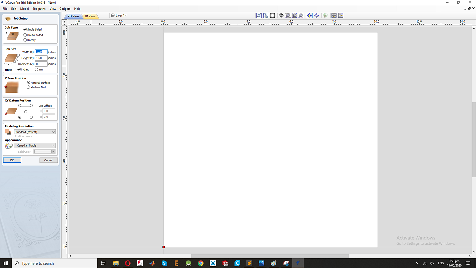
Software - VCarve:
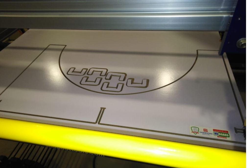
Bofore cutting assignment using Shopbot machine, to generate the G-code by using VCarve Software,which help us to maintain the XY coordinates in case if we stop the machine and some how its coordinates changes.Second the guided layers help us to prevent the machine from accidents. and I set the MDF board in Shopbot Machine and Fixed it with size and thickness,16.5mm.
First open the Vcarve Software and open new window:
Set the Job MDF board size and thickness,and use offset in both X and Y direction, this will be our guide to zero the XY positions
Now open the .dxf in Varve for further more Proces.
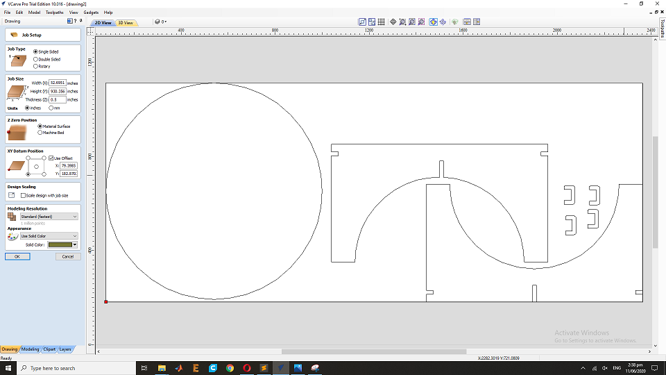
Now add the Layers and make a guide layer to leave space of 20mm from each side and make a border layer to mention boundaries.
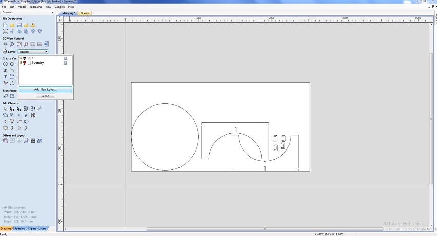
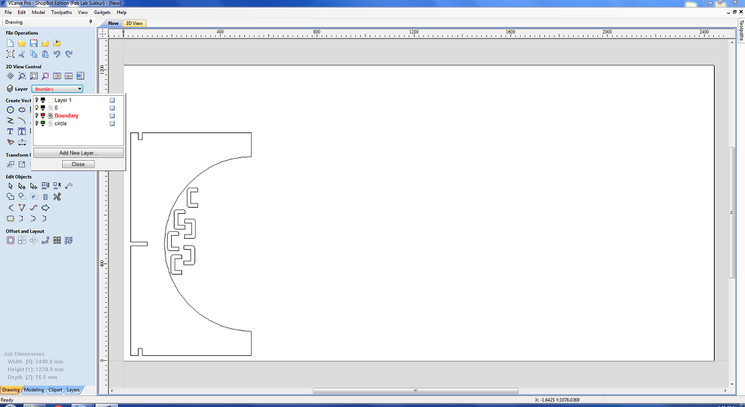
After layer this is the boundary .
Then I make two more layers one to set text engrave and other is for ouside cuts, to generated toolpaths separately for the cutting.
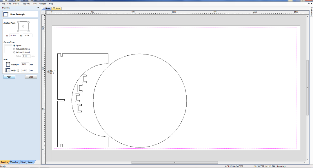
Then I made dog bones to detect the nerrow corners
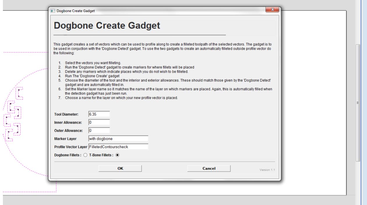
After the dog bones,I have test the Dog Bones.
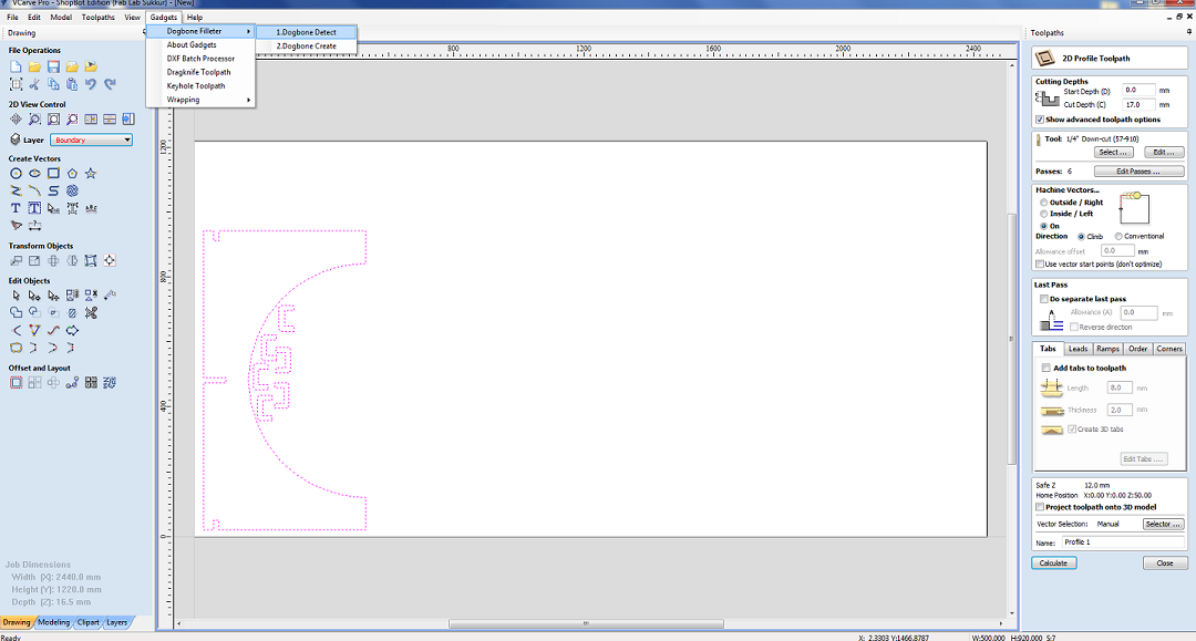
After that I create dog bones at the corners of the design
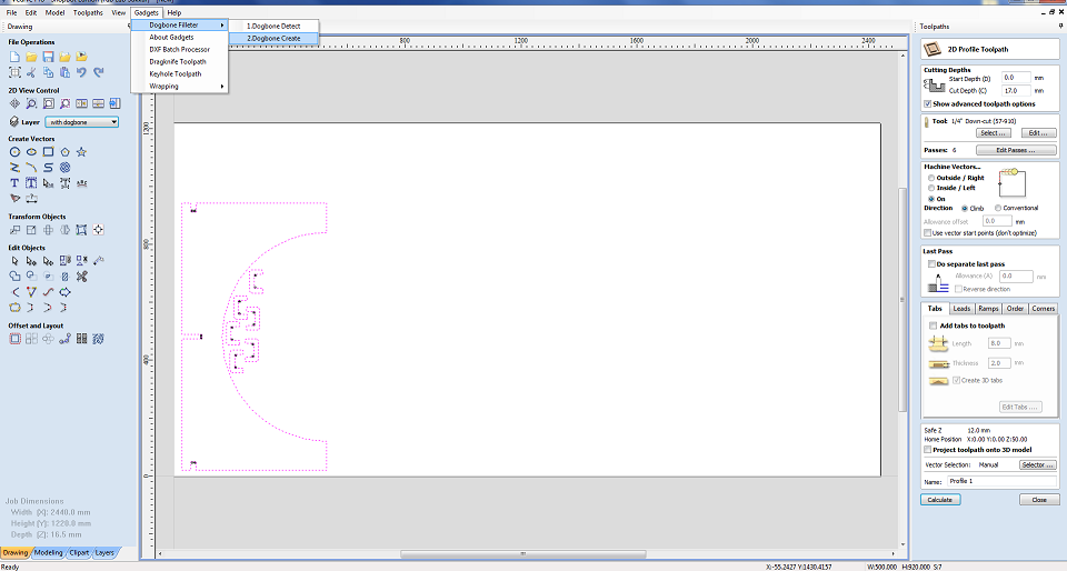
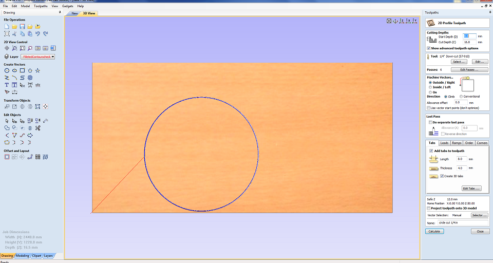
The next step is to generate toolpath now we need to cut the boundaries of the parts so we are using the profile toolpath
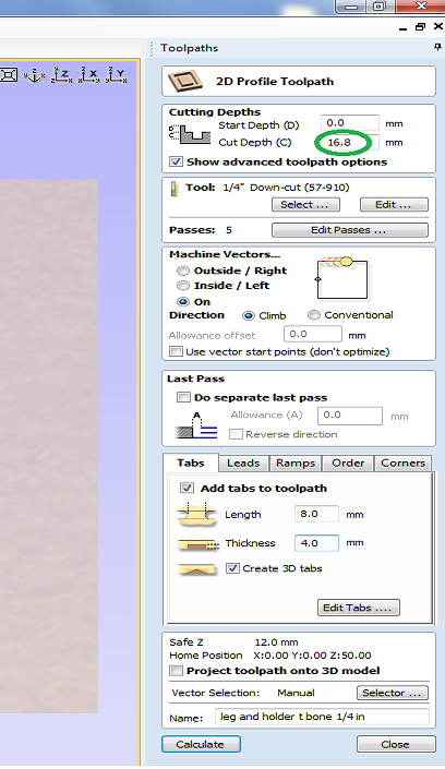
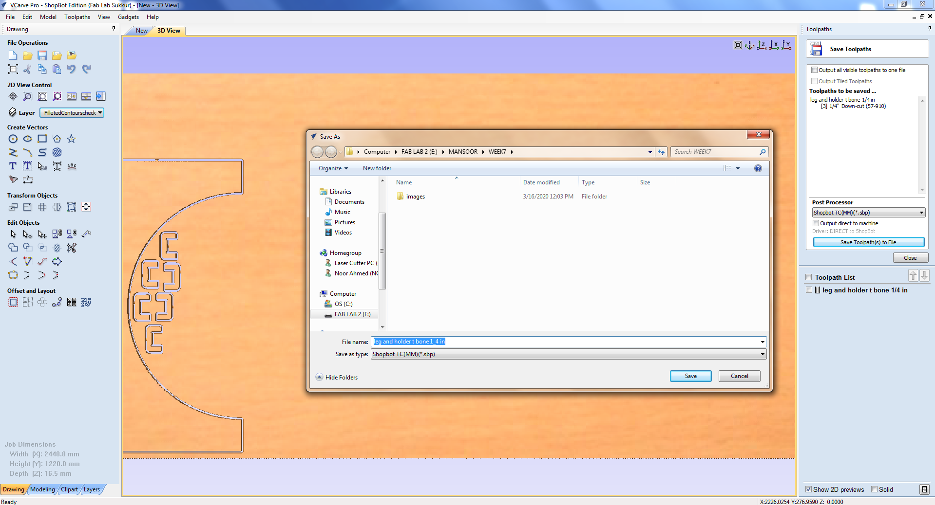
In toolpath settings I set Cut Depth as 16.8mm, Set Machine to run outside vectors, selected 1/4" Down-cut (57-910) drill bit and add tabs which help part to not move from place while cutting.After that making the toolpath of required parts,The generated toolpaths will be save as .sbp and then .sbp files given to shopbot to perform the job.
tool path for the side and support of the table.
CNC milling
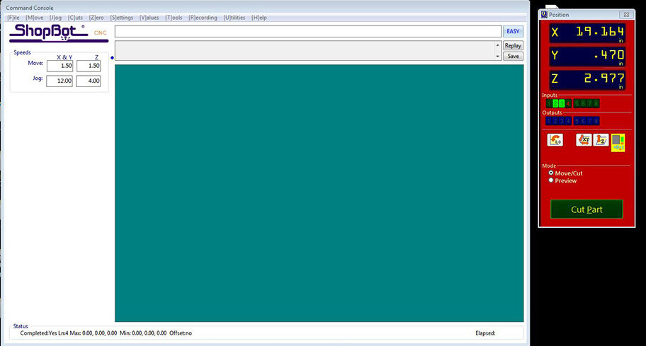
Before starting with the milling process, the first thing that needs to be done is to install the desired milling bit. As mentioned above, the bit has to be installed in the Collet and this is done with the help of these special spanners. Connect the system with the shopbot software installed using the 2 USB cables provided. On opening the software the axial location of the bit and a command like a screen appears.We need to move the drill bit to a point that we consider origin. To do this open the keypad option by clicking the yellow icon in the position menu.
Using the arrow key or the on-screen arrows move the bit to the desired origin point. Setting Z could be slightly tricky. The bit should touch the bed exactly at a point that it scraps the top layer.
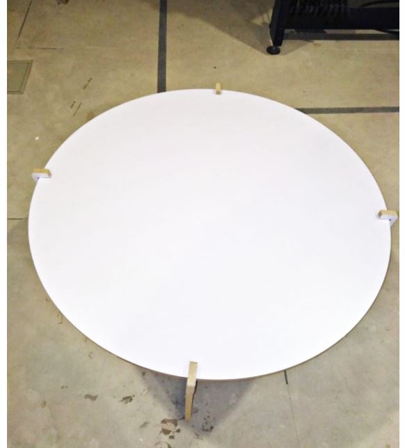
after the Shopbot milling the side:
Final shopbot milling the table and assembled table.
Conclusion
In this week , I have Learned about the CAD design,The Vcarve software use to generate G code and the tool path for the CNC Shopbot, In this week I have design CAD based round table in Solid work, after I have cut that table on laser cut at 4mm cardboard.and in last I have used the Vcarve software to generate the G code for the Shopbot. and in finaly I have operate the Shopbot machine to mill my table. it was very intertesting week.
Download all files from here

This work is licensed under a Creative Commons Attribution-NonCommercial-ShareAlike 4.0 International License