
Assignment
- Add an output device to a microcontroller board you've designed and program it to do something.
Idea of this Week
This week is out put week so I have plan to Work on the Nokia LCD. I will use LCD in my final Project, that Show the deiplay Power and Energy. So I am Using the NOKIA 5110 LCD. for more detail click here to find the data Sheet of the LCD. HERE
Nokia LCD 5110:
This is the Nokia LCD which i will used in my output week.
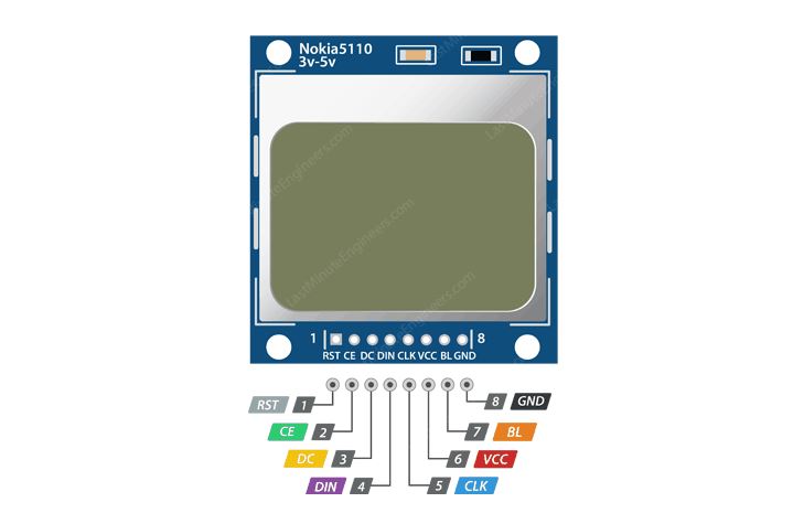
The Pin Diagram of the NOKIA 5110 LCD and details :
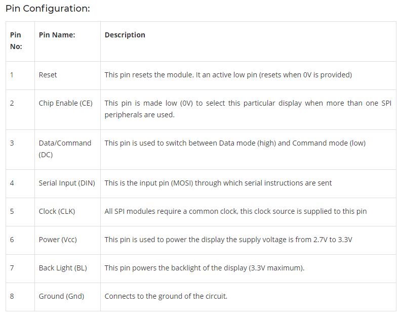
How to use Nokia 5110 Display module:
The Nokia 5110 module is commonly used with Arduino but it can also be used with any micro controller that supports SPI communication. The module works on 3.3V and hence all the pins are only 3.3V tolerant according to the datasheet. So if you are using a 5V micro controller (which most of us do) then it is recommended to use a logic level shifter like a potential divider to access the SPI pins of the display module.
The graphical LCD shown above is from spark fun, and hence you can find the soldering pad sets on both on top and to the bottom of the LCD of which we can use any desired set. However you can also find many clones in the market with pads on only one side, but still, they have the same pinouts and same functionality so you need not worry about the difference. All clones have the same dimensions (1.72’ × 1.72’) with 6 input pins.
You can easily interface Nokia 5110 module with Arduino by following the link and using the readily available libraries. If you are planning to interface with other micro controllers then you should read through the PCD8544 datasheet to know how to access its registers through SPI. For More detail and Help used this Link HERE
Features of Nokia5110 LCD module:
Applications:
Note :
For the this task we have lot of methods of programming , either I have to used the library to run this or I have to used manual programming form with out library. So I will not used any kind of libaray but I will use the manual programming by define the Pins.
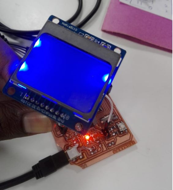
Interface of Nokia 5110 LCD with Micro Controller Board (Leonardo)
This is the Interface Diagram of the LCD with Board
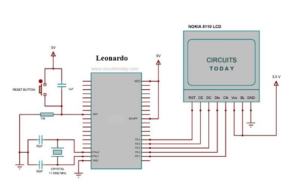
First of all I will connect the LCD With my Leonardo Board after that I will program the Board as per the connection of the LCD and then test it,. Where in LCD there is two term will Show one is Power in Watts and Energy in Kwh.
LCD Pins Interface with the Leonardo Board
First of all I have Interface pins LCD with the Leonardo.
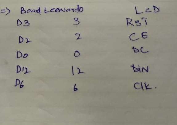
Now this is the LCD connection with Leonardo Board
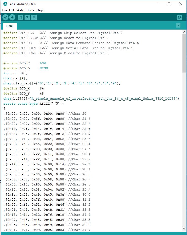
Now I want program the Leonardo for the LCD, this is the program
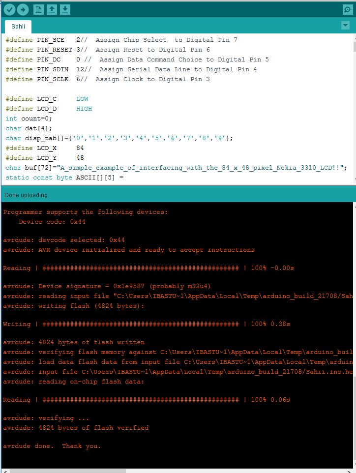
I have upload the program in Board and see the working behaviour of lCD.
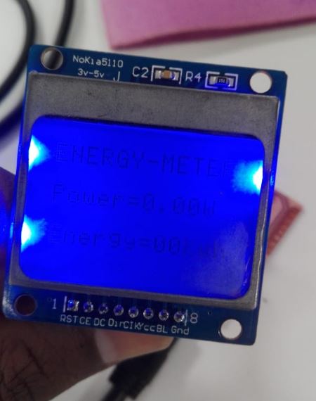
This the final result,that Lcd is working.
When Bl pin has zero voltage then lcd blinking like this.

Group Assignments
Group assignment: Measure the power consumption of an output device.
the group assignment, we have planed to measure the power Consumption of the Dc motor
Measure the Power Cosumption
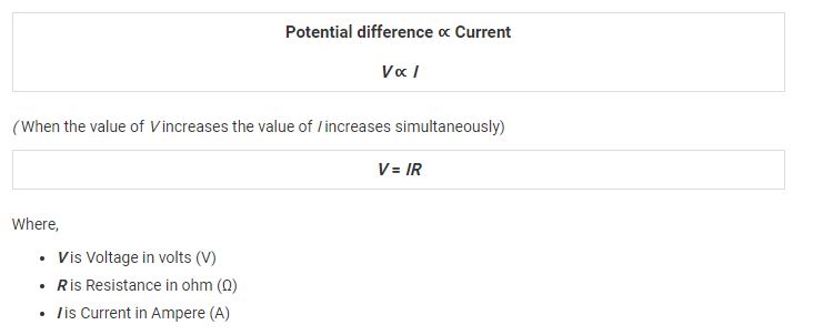
for calculation of Power , we know that Ohm law , it is state that "Ohm’s Law states that the current flowing through a conductor is directly proportional to the potential difference applied across its ends, provided the temperature and other physical conditions remain unchanged. Mathematically it can be represented as,"
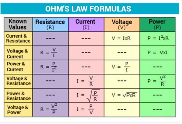
Power Calculation :
The rate at which energy is converted from the electrical energy of the moving charges to some other form of energy like mechanical energy, heat, magnetic fields or energy stored in electric fields, is known as electric power. The unit of power is watt. The electrical power can be calculated using the Ohm’s law and by substituting the values of voltage, current and resistance. linked HERE
Experiment :
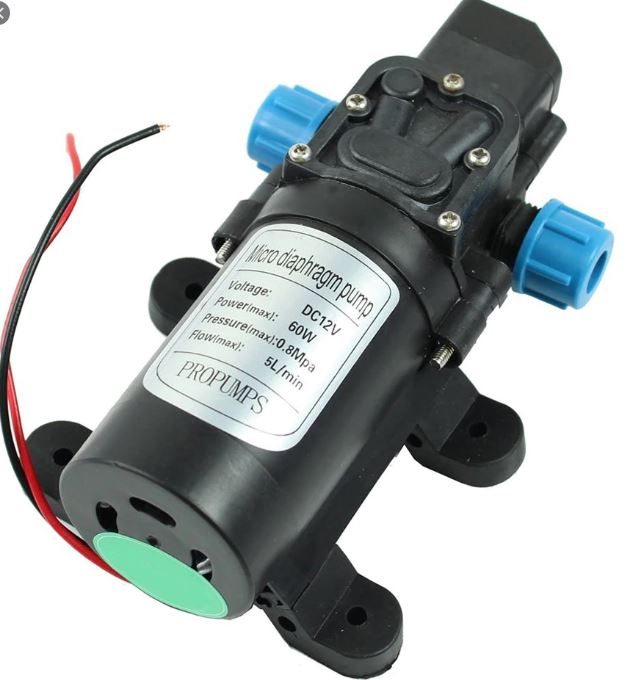
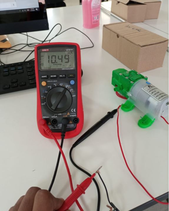
First, we have select the Dc Motor that Working on the 12.0V voltage, After that we have decide that we use the Digital Multimeter to measure the Voltage and Current and used the Power Calculation Formula to Caculate the Power,The DC water Pump Motor Having these Properties.
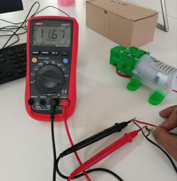
Now Connect Motor With Power Supply and Check the Input Voltage by using the Digital Multimeter, while Motor is Runing state:
After the voltage measurement, Now we have measured the current, So We have changed the connections of digital meter, for current we have used the meter as series Connections. in series connection meter looks like an Ammeter.
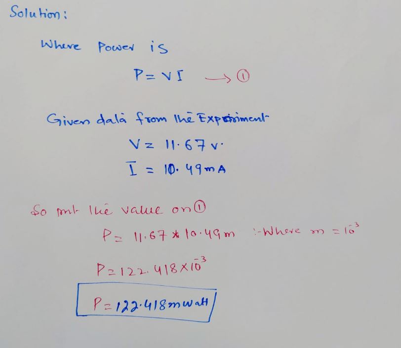
Now using the voltage and current that we measured to Calculate the Power :
Conculsion
In this week, I worked on LCD Nokai as the Output devices , So I have learned about the Nokia LCD Interface and programming.in this week we have also measure the power consumption of the DC water Pump Motor and calculate the power consumption.
