
Week 14 : Networking and Communications
the assignment for this week are:
The individual assignment
- Design and build a wired &/or wireless network connecting at least two processors
The group assignment
- Send a message between two projects
WHAT WE NEED TO DO ?
For this weeeks assignment we had to create an either wired or wireless Network which would be able to communicate two MCUs!!
Practically, it's my first time doing this kind, of thing and naturally I didn't have any clue and it literally took some time to adjust"my mind" to it !
Wired Networking
Serial Communication?
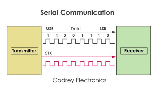
So in general for a communication to happen between two MCUs, it needs to be a sender and a receiver. Communication may be in one direction or in both directions! This can take place by using only a single wire or line. Hence, for a two-way digital communication, all what we need is wires between the transmitter and receiver.
- The serial communication can be classified in two types :
- Asynchronous: means sender provides a synchronization signal to the receiver before starting the transfer of each message.
- Synchronous: means sender and receiver use the same clock signal.
The most popular serial synchronous type of serial protocols available today in the market are, SPI, UART, I2C, CAN, USB,LIN,... - SPI Protocol
- I2C Protocol
- CAN Protocol
- USB
- Synchronous Serial Protocols
The advantage is you can interface more devices on the same bus.
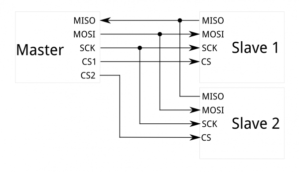
SPI (Serial peripheral interface) protocol send and receive data in a continuous stream without any interruption. This protocol is recommended for highspeed data communication is required. The maximum speed it can provide is 10 Mbps.
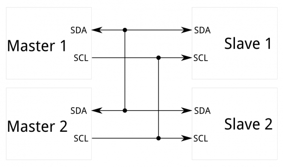
I2c (Inter-integrated circuit) is a two-wire bidirectional protocol used for an exchange of data between different devices on the same bus. I2c uses 7 bit or 10-bit address allowing to connect up to 1024 devices. But, it requires clock signal for generating start and stop conditions. The advantage is it provides data transfer at 400 kbps. It is suitable for onboard communication.
Unlike i2c, SPI has 4 wires. They are MOSI (Master out slave in), MISO (Master in slave out), Clock and Slave select signal. Theoretically, we can connect unlimited number of slaves and practically it depends on the load capacitance of the bus.This protocol is dedicated to vehicle systems or automobiles. It is a message-oriented protocol used for multiplex electric wiring to economize the copper. It is a multi-master multi serial bus used in applications such as automatic start/stop of vehicles, collision avoidance systems etc.
USB interface is the best alternative to serial or parallel ports. The data transfer associated with USB ports are quite faster than the serial and parallel interface. USB supports speeds from 1.5 Mbps (USB 1.0) to 4.8 Gbps (USB 3.0). Today most of the embedded devices use USB OTG (On the Go programming) technique for dumping the hex file to the microcontroller.
The individual assignment
Wireless Networking
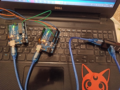
For this assignment I tried working with an Arduinosince we've been told that it's not necessary to make boards at first.
I decided on making an I2C bus using two Arduinos. We will program one master Arduino to command the other slave Arduino.
The only thing that it's going to be shown is the value recieved from the Master
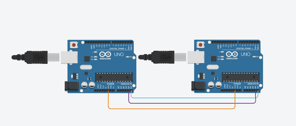
- Connect pins A4 and A5 on the Arduinos!
- Connect with a jumper the common GND line for both Arduinos.
CODE
For this part of the work I had to have code splitted in two codes to be uploaded to the Arduinos afterwards; the master code and the slave code:
Master Code
#include <Wire.h>

void setup() {
  Wire.begin();
  Serial.begin(9600);
}

byte x = 0;

void loop() {
  Wire.beginTransmission(8);
  Wire.write("value: ");
  Wire.write(x);
  Wire.endTransmission();

  x++;
  delay(500);
  Wire.requestFrom(8, 8);
  while (Wire.available()) {
    char c = Wire.read();
    Serial.print(c);
  }
  Serial.println();
  delay(100);
}
Code file
Before starting first of all, it's required to include the wire library first;
#include <Wire.h> Wire.begin(); ,this function is like adressing the master to join the I2C bus. If no argument is provided in the function, Arduino will begin working as a master.
Then we use the following functions to
begin a transmission to the device with the address 8, write the character, and then stop the transmission:
Wire.beginTransmission(8);
Wire.write("value: ");
Wire.write(x);
Wire.endTransmission()
TWire.h library here, but now we start the I2C bus using Wire.begin(8). This is like an invitation for the Arduino to join the I2C bus under the adresse 8: so in general all devices with address 8 will receive the transmission.
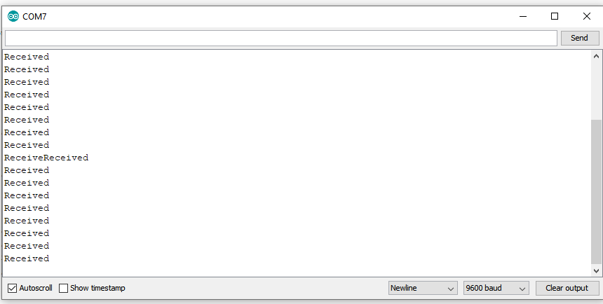
The data(byte) received from the Master are received as Characterchar c = Wire.read(); and printed afterward!!
After receiving the data the Arduino responds with message of 8 bytes: Wire.write("Received");
Slave Code
 #include <Wire.h>

void setup() {
  Wire.begin(8);
  Wire.onReceive(receiveEvent);
  Wire.onRequest(requestEvent);
  Serial.begin(9600);
}

void loop() {
  delay(100);
}

void receiveEvent(int howMany) {
  while (1 < Wire.available()) {
    char c = Wire.read();
    Serial.print(c);
  }
  int x = Wire.read();
  Serial.println(x);
}

void requestEvent() {
  Wire.write("Received");
}
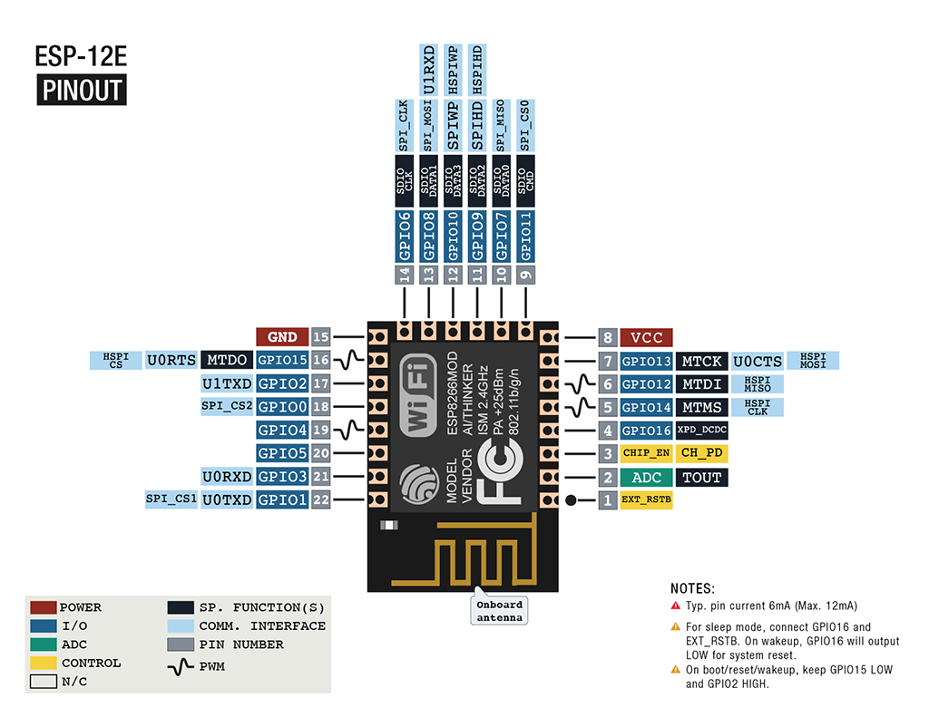
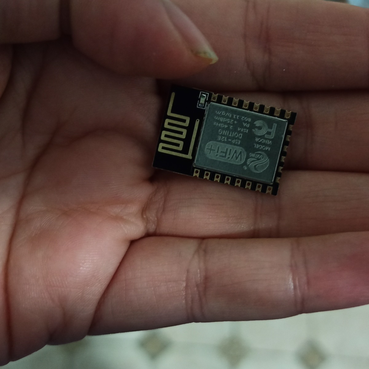
An ESP-12E Module board
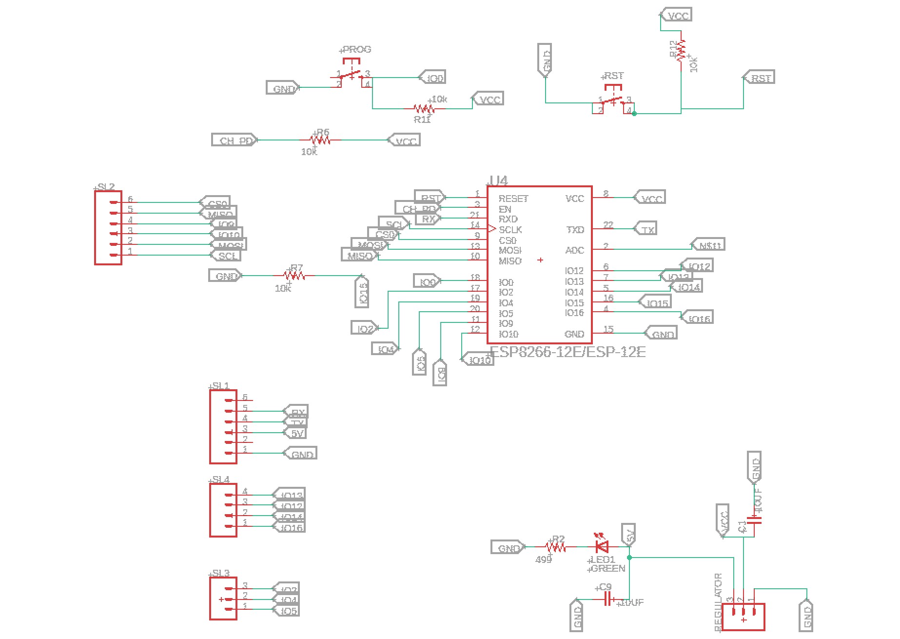
For this weeks assignment , I decided to make an ESP-12E Module board
Usage
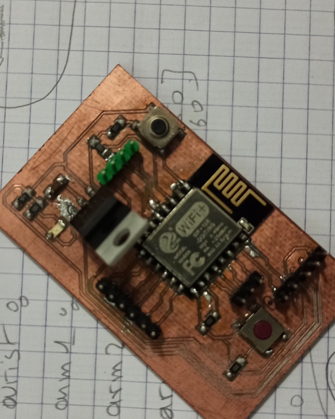
Designing the board
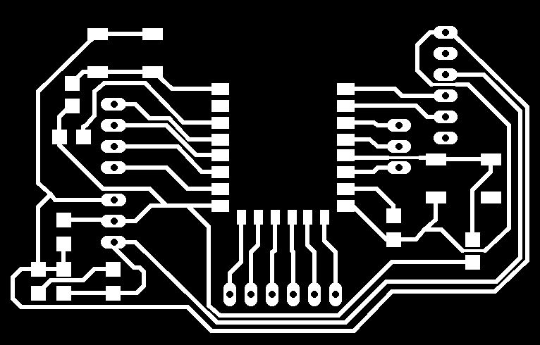
And the piece of art is ready to be soldered
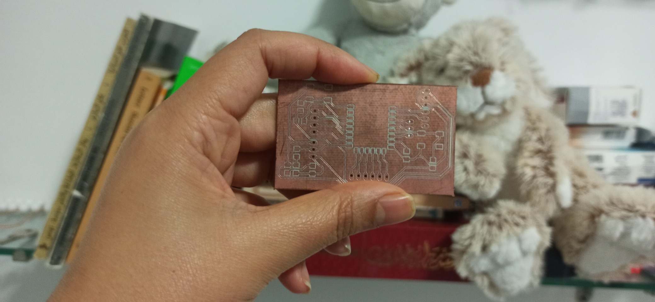
SOLDERING
For this board what I needed is the following:
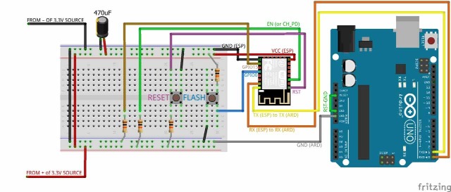
Arduino
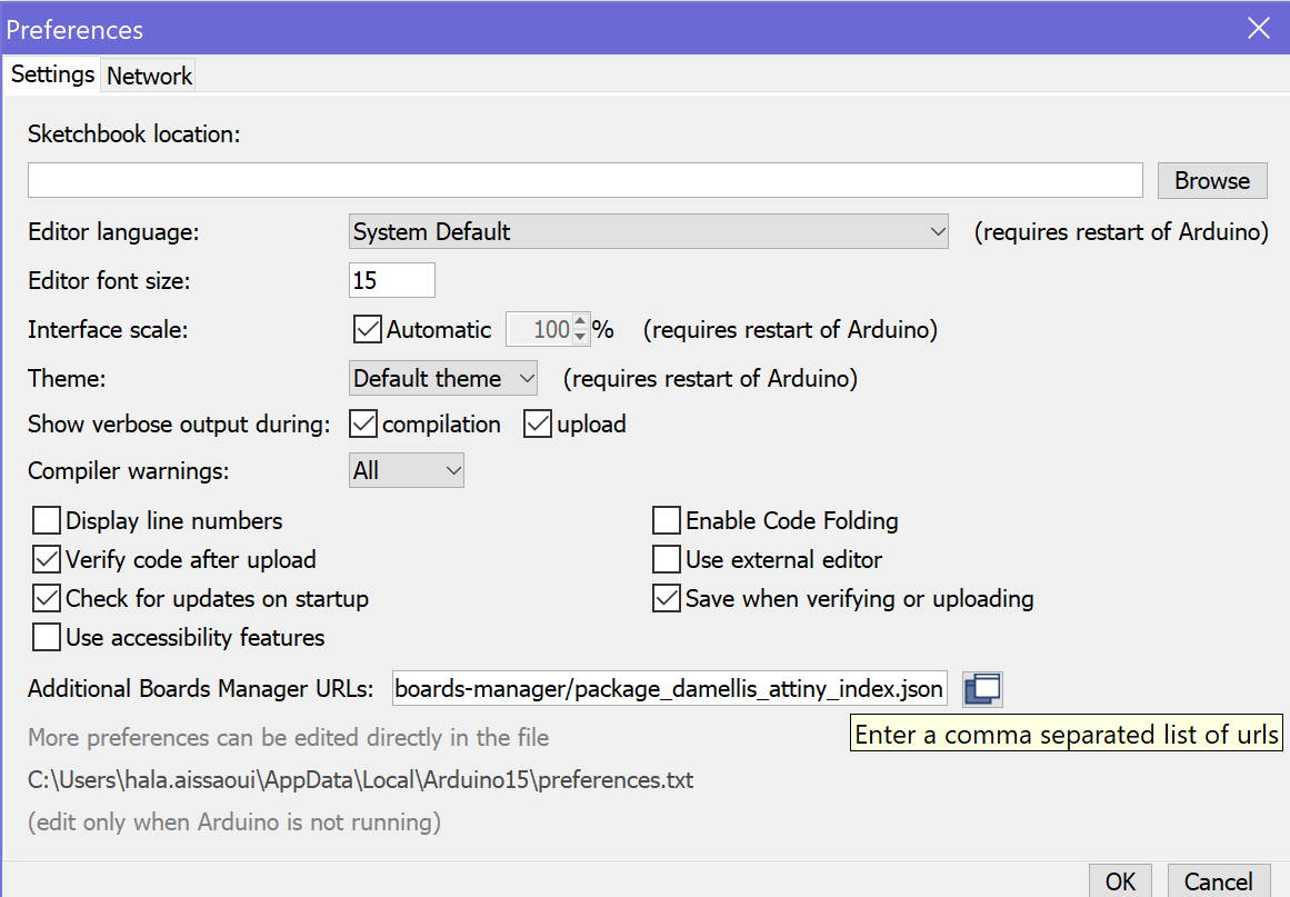
Since you're not going to upload the code to our usual microship, therefore you need to make some changes in the Arduino app
Go to FILE>PREFERENCES and then copy and paste this link as shown bellow in additional Board manager URLs https://arduino.esp8266.com/stable/package_esp8266com_index.json
Then download the library of the ESP8266 Boards
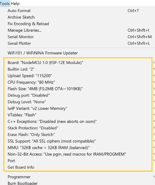
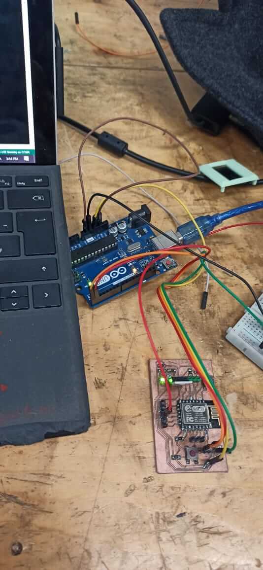
and then connect the 4 PINsRX to RX , TX to TX, GND to GND and the VCC to the VCC to the ARDUINO to upload the code and while the code is uploading I needed to keep clicking on one of the PUSH BUTTONS the programmer ,and one click on the RESET button
#include <ESP8266WiFi.h>
#include <WiFiClient.h>
#include <ESP8266WebServer.h>

#ifndef STASSID
#define STASSID "your-ssid"
#define STAPSK  "your-password"
#endif

const char* ssid = STASSID;
const char* password = STAPSK;

ESP8266WebServer server(80);

//Check if header is present and correct
bool is_authenticated() {
  Serial.println("Enter is_authenticated");
  if (server.hasHeader("Cookie")) {
    Serial.print("Found cookie: ");
    String cookie = server.header("Cookie");
    Serial.println(cookie);
    if (cookie.indexOf("ESPSESSIONID=1") != -1) {
      Serial.println("Authentication Successful");
      return true;
    }
  }
  Serial.println("Authentication Failed");
  return false;
}

//login page, also called for disconnect
void handleLogin() {
  String msg;
  if (server.hasHeader("Cookie")) {
    Serial.print("Found cookie: ");
    String cookie = server.header("Cookie");
    Serial.println(cookie);
  }
  if (server.hasArg("DISCONNECT")) {
    Serial.println("Disconnection");
    server.sendHeader("Location", "/login");
    server.sendHeader("Cache-Control", "no-cache");
    server.sendHeader("Set-Cookie", "ESPSESSIONID=0");
    server.send(301);
    return;
  }
  if (server.hasArg("USERNAME") && server.hasArg("PASSWORD")) {
    if (server.arg("USERNAME") == "admin" &&  server.arg("PASSWORD") == "admin") {
      server.sendHeader("Location", "/");
      server.sendHeader("Cache-Control", "no-cache");
      server.sendHeader("Set-Cookie", "ESPSESSIONID=1");
      server.send(301);
      Serial.println("Log in Successful");
      return;
    }
    msg = "Wrong username/password! try again.";
    Serial.println("Log in Failed");
  }
  String content = "<html><body><form action='/login' method='POST'>To log in, please use : admin/admin<br>";
  content += "User:<input type='text' name='USERNAME' placeholder='user name'><br>";
  content += "Password:<input type='password' name='PASSWORD' placeholder='password'><br>";
  content += "<input type='submit' name='SUBMIT' value='Submit'></form>" + msg + "<br>";
  content += "You also can go <a href='/inline'>here</a></body></html>";
  server.send(200, "text/html", content);
}

//root page can be accessed only if authentication is ok
void handleRoot() {
  Serial.println("Enter handleRoot");
  String header;
  if (!is_authenticated()) {
    server.sendHeader("Location", "/login");
    server.sendHeader("Cache-Control", "no-cache");
    server.send(301);
    return;
  }
  String content = "<html><body><H2>hello, you successfully connected to esp8266!</H2><br>";
  if (server.hasHeader("User-Agent")) {
    content += "the user agent used is : " + server.header("User-Agent") + "<br><br>";
  }
  content += "You can access this page until you <a href=\"/login?DISCONNECT=YES\">disconnect</a></body></html>";
  server.send(200, "text/html", content);
}

//no need authentication
void handleNotFound() {
  String message = "File Not Found\n\n";
  message += "URI: ";
  message += server.uri();
  message += "\nMethod: ";
  message += (server.method() == HTTP_GET) ? "GET" : "POST";
  message += "\nArguments: ";
  message += server.args();
  message += "\n";
  for (uint8_t i = 0; i < server.args(); i++) {
    message += " " + server.argName(i) + ": " + server.arg(i) + "\n";
  }
  server.send(404, "text/plain", message);
}

void setup(void) {
  Serial.begin(115200);
  WiFi.mode(WIFI_STA);
  WiFi.begin(ssid, password);
  Serial.println("");

  // Wait for connection
  while (WiFi.status() != WL_CONNECTED) {
    delay(500);
    Serial.print(".");
  }
  Serial.println("");
  Serial.print("Connected to ");
  Serial.println(ssid);
  Serial.print("IP address: ");
  Serial.println(WiFi.localIP());


  server.on("/", handleRoot);
  server.on("/login", handleLogin);
  server.on("/inline", []() {
    server.send(200, "text/plain", "this works without need of authentication");
  });

  server.onNotFound(handleNotFound);
  //ask server to track these headers
  server.collectHeaders("User-Agent", "Cookie");
  server.begin();
  Serial.println("HTTP server started");
}

void loop(void) {
  server.handleClient();
}
After I programmed it and checked that it works, I had to make something using it, so since I didn't put any LED connected directly to the ESP, I put a one in the bread board, one side is connected to GND and the other with a 1O Ohm resistor to theGIO10 of the board
.jpeg)
So the code for this one is the following
<
// Load Wi-Fi library
#include <ESP8266WiFi.h>
// Replace with your network credentials
const char* ssid = "El FabSpace Lac";
const char* password = "Think_Make_Share";
// Set web server port number to 80
WiFiServer server(80);
// Variable to store the HTTP request
String header;
// Auxiliar variables to store the current output state
String output5State = "off";
String output4State = "off";
// Assign output variables to GPIO pins
#define output5 10
void setup() {
Serial.begin(115200);
// Initialize the output variables as outputs
pinMode(output5, OUTPUT);
// Set outputs to LOW
digitalWrite(output5, LOW);
// Connect to Wi-Fi network with SSID and password
Serial.print("Connecting to ");
Serial.println(ssid);
WiFi.begin(ssid, password);
while (WiFi.status() != WL_CONNECTED) {
delay(500);
Serial.print(".");
}
// Print local IP address and start web server
Serial.println("");
Serial.println("WiFi connected.");
Serial.println("IP address: ");
Serial.println(WiFi.localIP());
server.begin();
}
void loop(){
WiFiClient client = server.available(); // Listen for incoming clients
if (client) { // If a new client connects,
Serial.println("New Client."); // print a message out in the serial port
String currentLine = ""; // make a String to hold incoming data from the client
while (client.connected()) { // loop while the client's connected
if (client.available()) { // if there's bytes to read from the client,
char c = client.read(); // read a byte, then
Serial.write(c); // print it out the serial monitor
header += c;
if (c == '\n') { // if the byte is a newline character
// if the current line is blank, you got two newline characters in a row.
// that's the end of the client HTTP request, so send a response:
if (currentLine.length() == 0) {
// HTTP headers always start with a response code (e.g. HTTP/1.1 200 OK)
// and a content-type so the client knows what's coming, then a blank line:
client.println("HTTP/1.1 200 OK");
client.println("Content-type:text/html");
client.println("Connection: close");
client.println();
// turns the GPIOs on and off
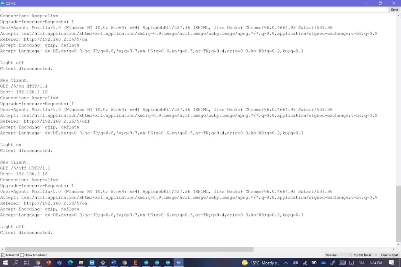
if (header.indexOf("GET /5/on") >= 0) {
Serial.println("Light on");
output5State = "on";
digitalWrite(output5, HIGH);
} else if (header.indexOf("GET /5/off") >= 0) {
Serial.println("Light off");
output5State = "off";
digitalWrite(output5, LOW);
}
// Display the HTML web page
client.println("<html>");
client.println("<head><meta name=\"viewport\" content=\"width=device-width, initial-scale=1\">");
client.println("<link rel=\"icon\" href=\"data:,\">");
// CSS to style the on/off buttons
// Feel free to change the background-color and font-size attributes to fit your preferences
client.println("<style>html { font-family: Helvetica; display: inline-block; margin: 0px auto; text-align: center;}");
client.println(".button { background-color: #195B6A; border: none; color: white; padding: 16px 40px;");
client.println("text-decoration: none; font-size: 30px; margin: 2px; cursor: pointer;}");
client.println(".button2 {background-color: #77878A;}</style></head>");
// Web Page Heading
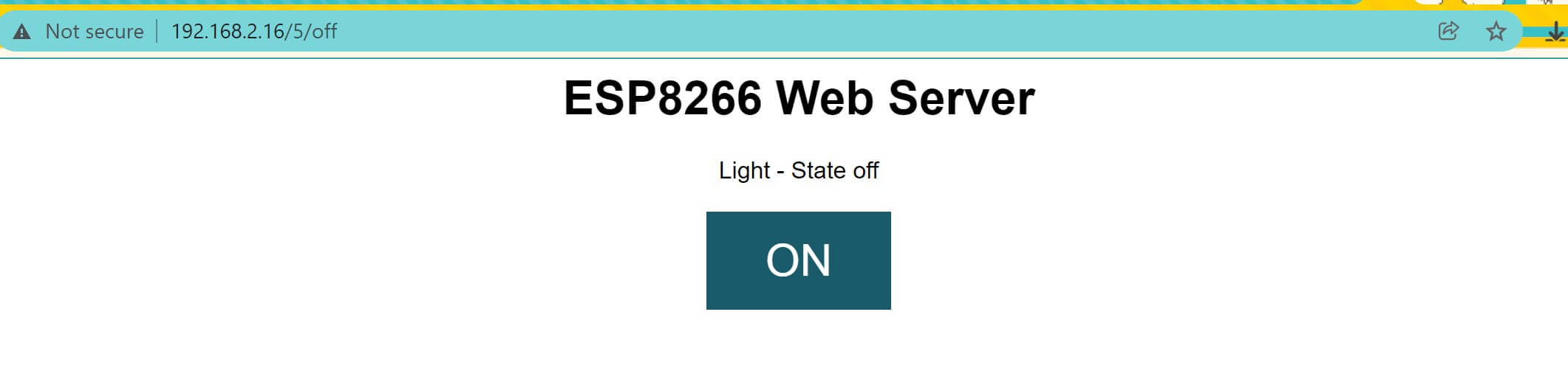
client.println("<body><h1>ESP8266 Web Server</h1>");
// Display current state, and ON/OFF buttons for GPIO 5
client.println("<p>Light - State " + output5State + "</p>");
// If the output5State is off, it displays the ON button
if (output5State=="off") {
client.println("<p><a href=\"/5/on\"><button class=\"button\">ON</button></a></p>");
} else {
client.println("<p><a href=\"/5/off\"><button class=\"button button2\">OFF</button></a></p>");
}
// Break out of the while loop
break;
}else { // if you got a newline, then clear currentLine
currentLine = "";
}
} else if (c != '\r') { // if you got anything else but a carriage return character,
currentLine += c; // add it to the end of the currentLine
}
}
}
// Clear the header variable
header = "";
// Close the connection
client.stop();
Serial.println("Client disconnected.");
Serial.println("");
}
}
while it starts to upload, keep pushing the Program button and then one click on the the RESET
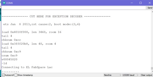
and thing would appear once you open the serial Monitor
copy and paste this
Host: 192.168.2.16
in your browser
and a window is going to appear
Group Assignment
For this We had to send a message between two projects
Here's the direct link for this part of the Assignment
Files
Board
Schematic
Arduino code