
Week 11 : Output devices
the assignments for this week are:
The individual assignment
- Add an output device to a microcontroller board you've designed!
- Program it to do something
The group assignment:
Group Assignment
Check this Link for this!
What is an Output Device?
Output devices in electronic systems transfer energy from the electrical energy that has been processed to another kind of energy, often light, sound or movement (kinetic). Output devices can be digital or analogue. Devices which perform an “Output” function are generally called Actuators.
It's the 5th week since the start of the entire countrys lockdown! So yaay -_-" , once again I will use the simulator of TinkerCAD!
SO one of my basic Output devices that I'm going to use for my final project is a device that's the base for my Humidifier; the Mist maker!
The principle behinf water rurning into mist :
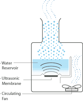
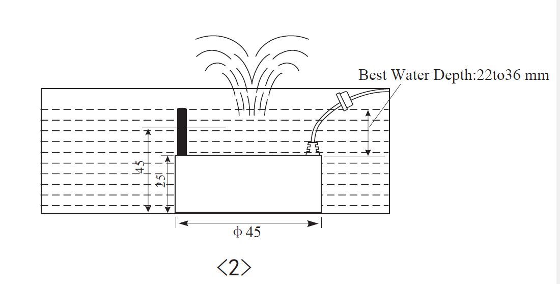
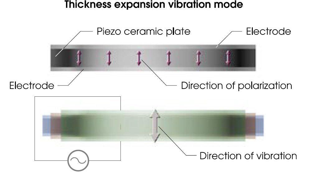
Piezo resonators areinsrted and fixed to the base of water receptacles build into humidifiers. These resonators apply vibration energy generated from voltage supplied by drive circuits directly into the water. During this process, the vibration energy is transmitted into a direction that is perpendicular to the resonant surface of the piezo resonator By optimizing the water depth, it is possible to generate a water colimn where energy above the axis of transmission on the water's surface is concentrated. A concentrated surface tension wave is generated at the end of that column that is both minute and profuse. The result is that surface tension on the swelled surface is reduced and the water surface is devided in minute regions corresponding to the length of the surface tensions waves. Each of these areas become individual particles, are lifted up by the air from a ventilation fan and distributed into the air.
This entire process is believed to be principle for turning water into mist using ultrasonic resonators.
Once again I used TinkerCad to simulate my operation. But since there wasn't what I need, I decided on using the closed thing which is a BUZZER that basically uses the same principle as my device; Changing the electric energy into sound!
UPDATES
We've been told that it's not necissary to make a new board and mill it and use it for this Assignment. So it was enough to use the Arduino!
Anyway, like what I said before and since that I'm going to have the ceramic transducteur piezo for my final project, I decided to have something similar for this Week A BUZZER as my output device here.
But what's a Buzzer?
Buzzer
A buzzer or beeper is an audio signalling device, which may be mechanical, electromechanical, or piezoelectric (piezo for short). Typical uses of buzzers and beepers include alarm devices, timers, and confirmation of user input such as a mouse click or keystroke.
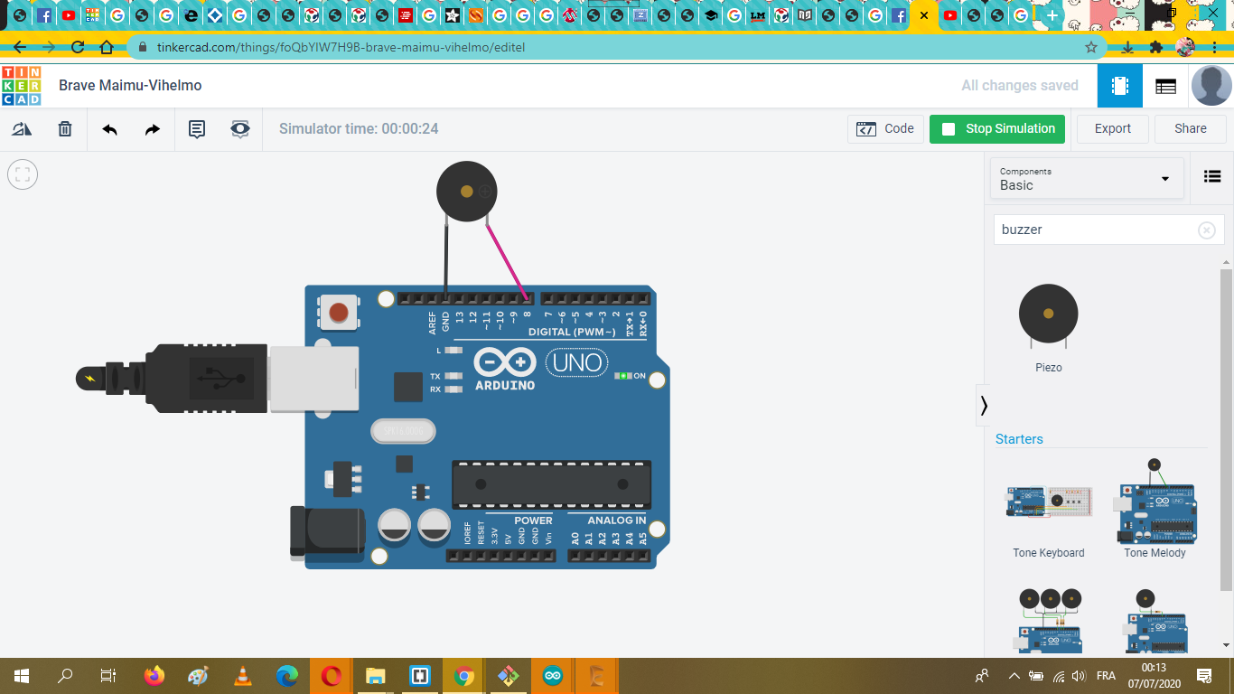
I used Tinkercad to simulate the operation online,
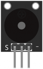
This is how normally are buzzer wired, with two sides; the - and +
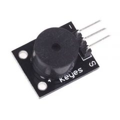
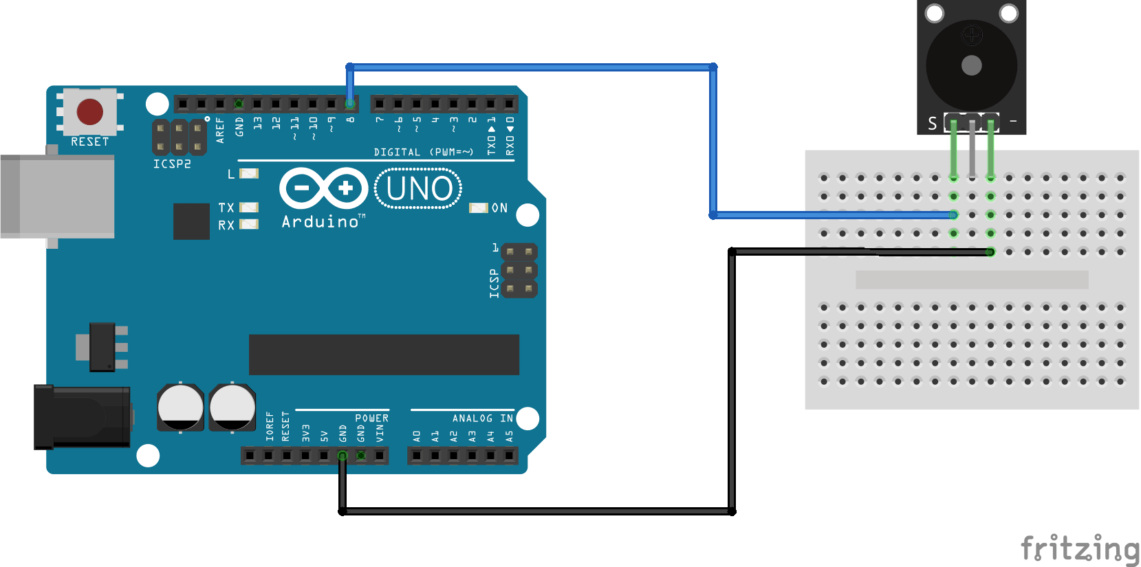
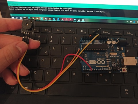
The one that I'm using for this Assignment is a 3 pinned buzzer , model KY-006!
I only needed to connect only two pins out of the 3, one to the GND and the other to the Arduino pins; Connect the positive side of the Buzzer to pin 3, then the negative side to ground(GND) pin on the Arduino.
Thank goodness that wiring the buzzer doesn't need any specific library to be uploaded!!!
Generating the code
For this part, I choose a Super Mario iconic melody
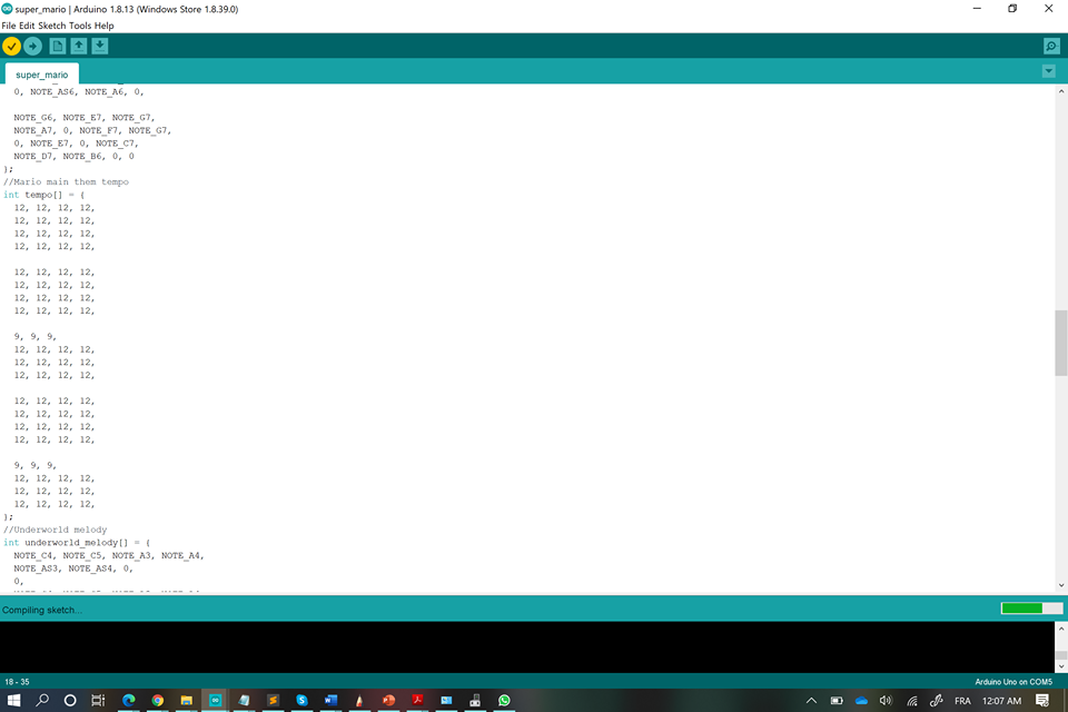
The code SUPER MARIO
Not only that, I tried the soundtrack of the Game of thrones
The code GOT
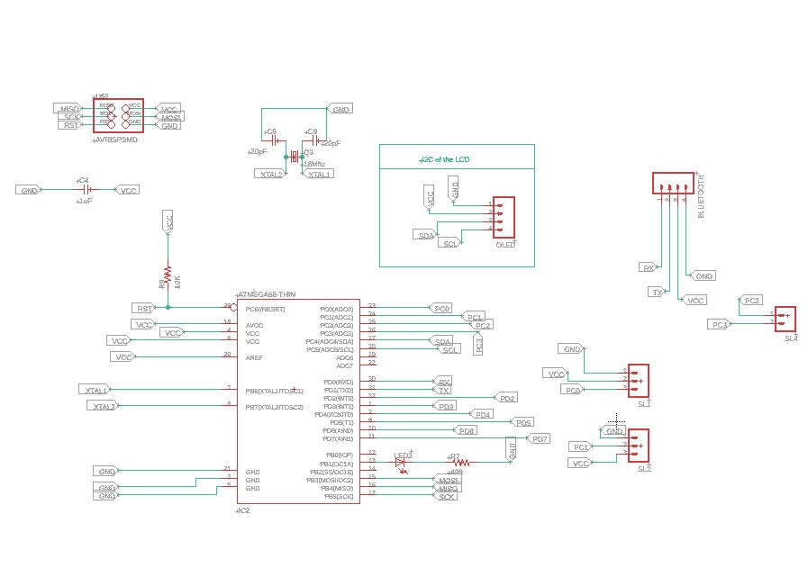
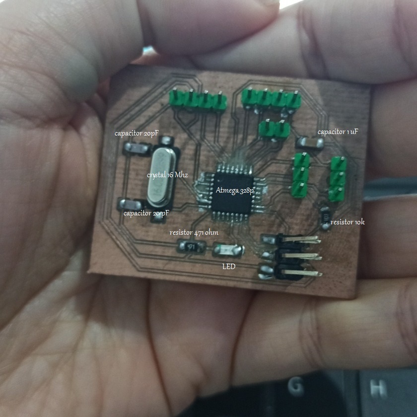
As I already said in the Week 09 we had to make our boards, and once again we were obliged to use the ATMEGA 328P instead of the Attiny, so for this week's assignment I, choose to used as an output device the OLED 1,3 I2C.
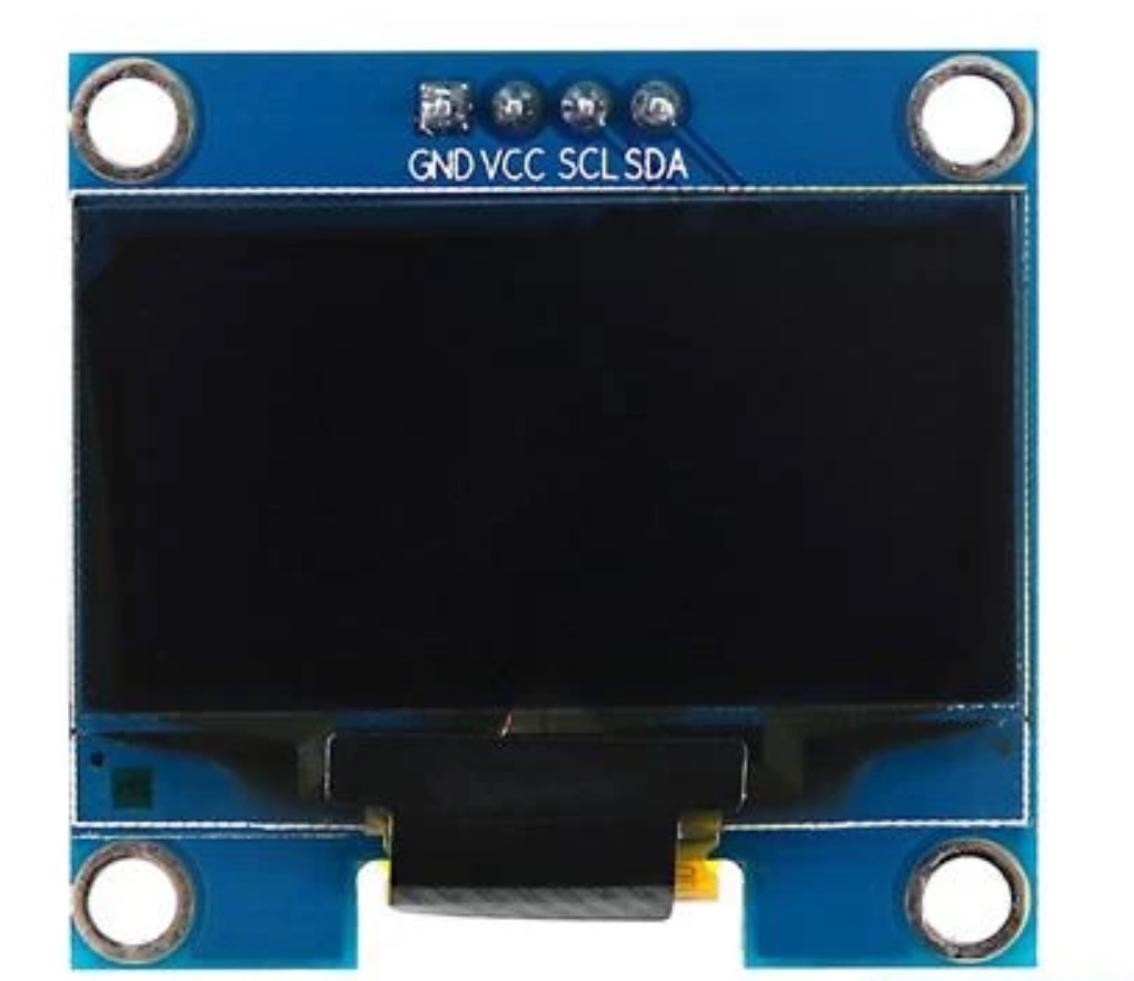
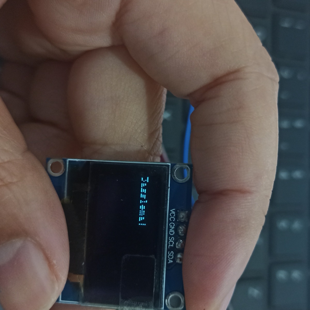
OLED 1.3 I2C (Datasheet)
It's an OLED monochrome 128x64 dot matrix display module with I2C Interface. Comparing with LCD, OLED screens are way more competitive, which has a number of advantages such as high brightness, self-emission, high contrast ratio, wide viewing angle, wide temperature range, and low power consumption. It is compatible with Arduino. It is easy to use with the help of the U8glib library for Arduino.
So since I'm using the ATMEGA 328p I had to make use of it, since there's alot of pins, for the reasong
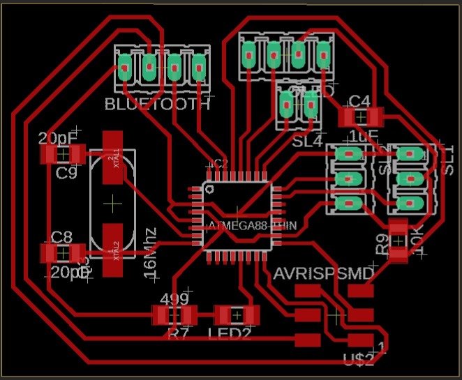
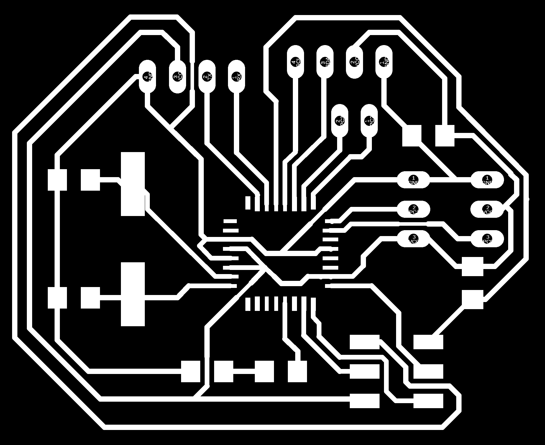
milled it
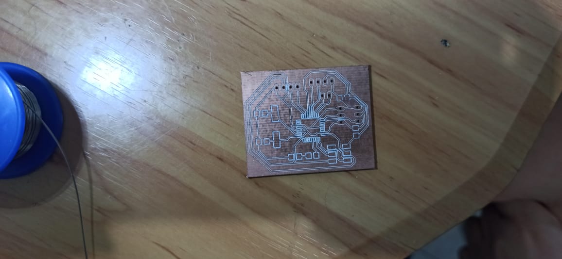
and solder it
For this board, I put a simple code and did the usual thing.
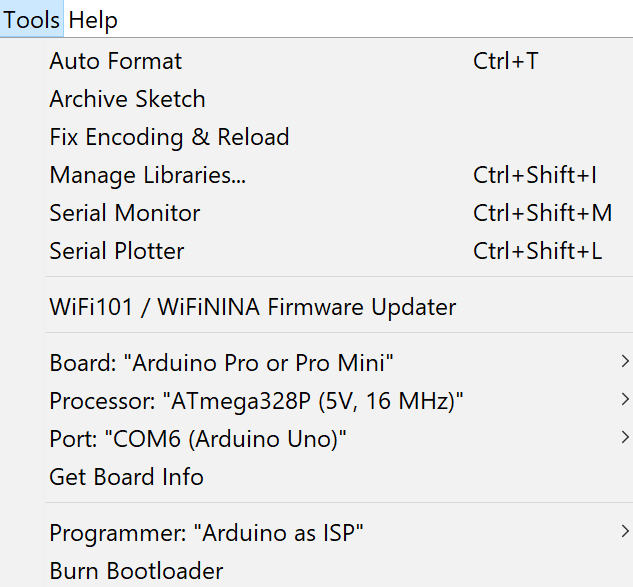
First of all before anything we have to do the BURN BOOTLOADER step like in the 6th week
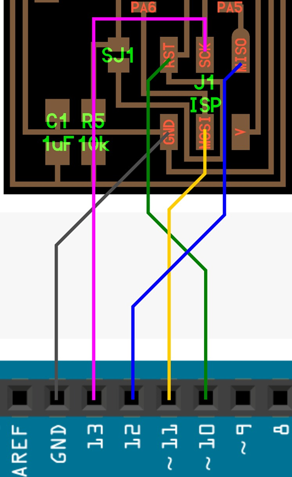
Tools>Board>Arduino AVR Boards>Arduino Pro or Pro mini and then on the Processor tab select your Atmega!
The code
#include <Wire.h>
#include <Adafruit_GFX.h>
#include <Adafruit_SSD1306.h>

#define SCREEN_WIDTH 128 // OLED display width,  in pixels
#define SCREEN_HEIGHT 64 // OLED display height, in pixels

// declare an SSD1306 display object connected to I2C
Adafruit_SSD1306 oled(SCREEN_WIDTH, SCREEN_HEIGHT, &Wire, -1);

void setup() {
  Serial.begin(9600);

  // initialize OLED display with address 0x3C for 128x64
  if (!oled.begin(SSD1306_SWITCHCAPVCC, 0x3C)) {
    Serial.println(F("SSD1306 allocation failed"));
    while (true);
  }

  delay(2000);         // wait for initializing
  oled.clearDisplay(); // clear display

  oled.setTextSize(1);          // text size
  oled.setTextColor(WHITE);     // text color
  oled.setCursor(0, 10);        // position to display
  oled.println("3asslema!"); // text to display
  oled.display();               // show on OLED
}

void loop() {
}
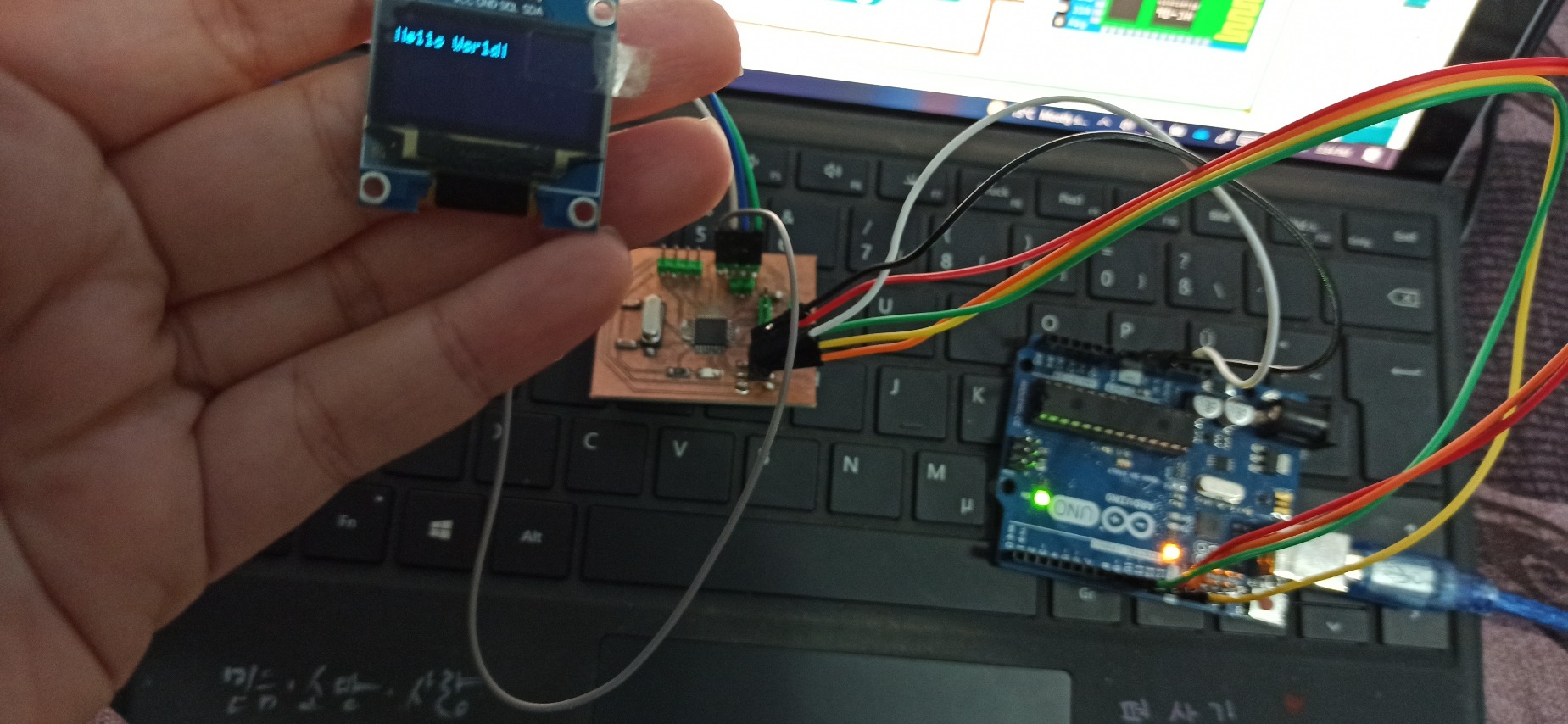
After that everything worked so perfectly
And then play with the code as much as you want.
My Files
OLED codeOutput SCHEMATIC
Ouput BOARD