
Week 09 : Input devices
the assignment for this week are:
The group Assignment
- Probe an input device's analog levels and digital signals
The individual assignment
- Measure something: add a sensor to a microcontroller board that you have designed and read it.
The group Assignment
The direct link to the group assignment
Individual Assignement
Since it's the second week after the total shutdown of the country, so once again we are going to work with Arduino as a temporary solution.
So what do we know for now so far?
Input devices:Sensors and Transducers
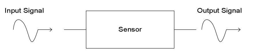
For this week, we're going to talk about a specific devices that automatically inputs data about the physical environment around it and records it into a computer system, where the data is constantly changing and can be measured.
These devices are called Sensors.
Basically, a sensor (or Transducer) is a device that converts a real-world property (e.g. temperature) into data that a computer can process.
They're used extensively in monitoring / measuring / data logging systems, and also in computer control systems.
A sensor measures a specific property data and sends a signal to the microprocessor (computer). Usually this is an analogue signal so it needs to be converted into digital data for the computer to process. This is done using by an Analogue-to-Digital Converter (ADC).
Analogue and Digital Sensors
Analogue Sensors:
they produce a continuous output signal or voltage which is generally proportional to the quantity being measured. Physical quantities such as Temperature, Speed, Pressure, Displacement, Strain etc are all analogue quantities as they tend to be continuous in nature. For example, the temperature of a liquid can be measured using a thermometer or thermocouple which continuously responds to temperature changes as the liquid is heated up or cooled down.
Digital Sensors :
As its name implies, Digital Sensors produce a discrete digital output signals or voltages that are a digital representation of the quantity being measured. Digital sensors produce a Binary output signal in the form of a logic “1” or a logic “0”, (“ON” or “OFF”). This means then that a digital signal only produces discrete (non-continuous) values which may be outputted as a single “bit”, (serial transmission) or by combining the bits to produce a single “byte” output (parallel transmission).
Sensor that I'm going to work with:
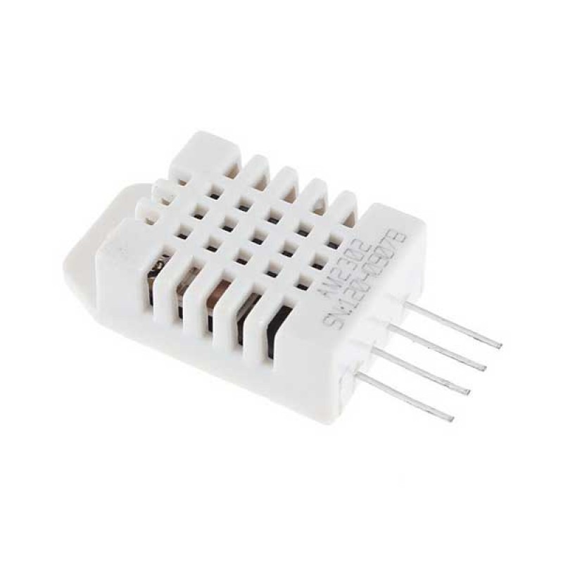
A humidity and temperature sensor - DHT11(Datasheet)
The DHT11 is a commonly used Temperature and humidity sensor. The sensor comes with a dedicated NTC to measure temperature and an 8-bit microcontroller to output the values of temperature and humidity as serial data. The sensor is also factory calibrated and hence easy to interface with other microcontrollers. The sensor can measure temperature from 0°C to 50°C and humidity from 20% to 90% with an accuracy of ±1°C and ±1%.
However since I'm only using TinkerCad online to simulate my input device; the problem is that there's not that very wide option to choose from, I couldn't find a DHT11 sensor to be used here, thus I only used a Temperature sensor and simulated my board using it!
One of the IDEAs that I got when I started working on my final project is that how to make it works on it's own and since I'm working with a humidifier and a DHT , so the question is gow to make both of these work simultaneously?!
We've been told to work with the arduino for this assignment especially after what happened in the last weeks.
In short I'm gonna try working with the DHT as my Input device and gonna try to link it with the BUZZER.
I tried to do something cooler with LEDs too , but it didn't won't to work , plus it had so much wiring T_T
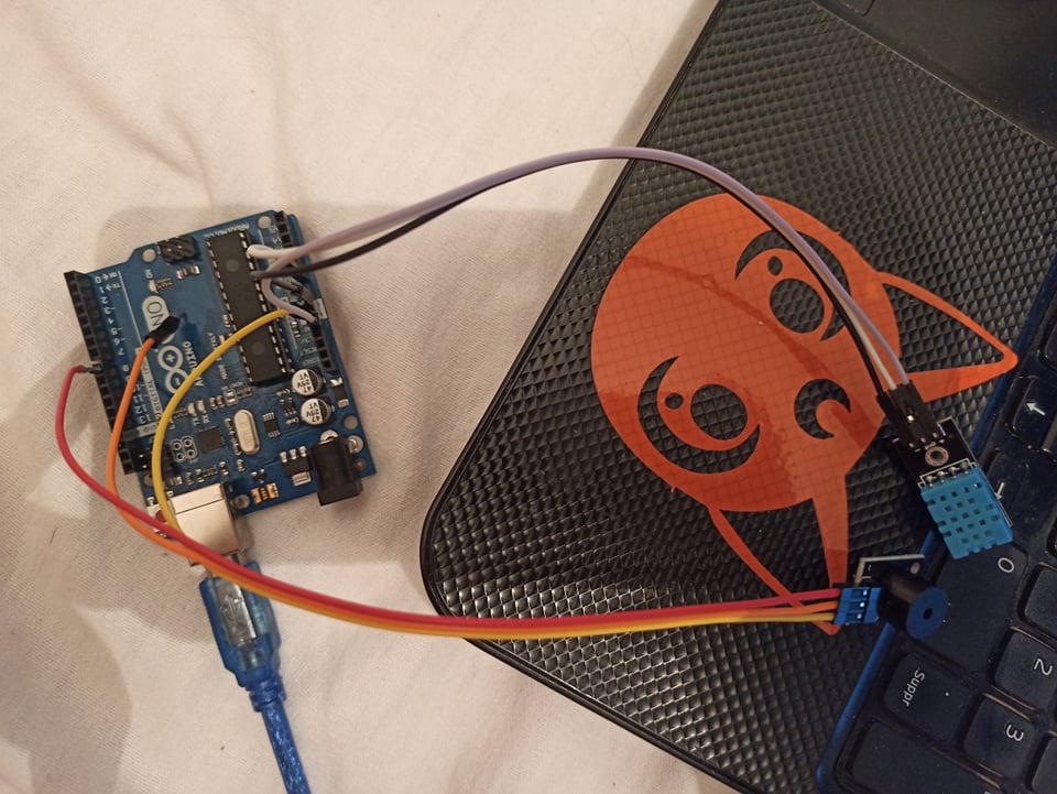
As I said , for this part of the work I needed a DHT11, a KY-006 Buzzer, and Jumper wires and yeah let's start wiring them!!
The Connection
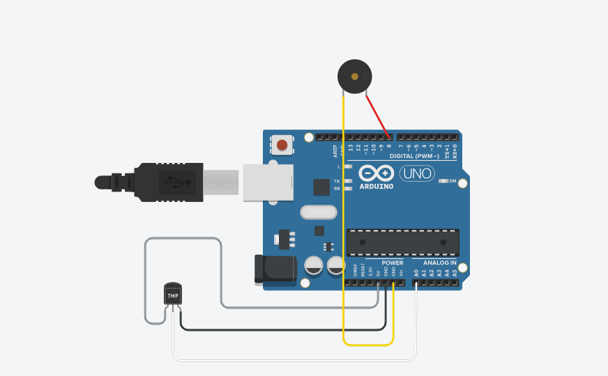
For this one , I didn't really need to use the breadboard here!!
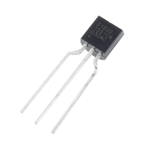
the sensor that I'm using has 3 pins!
The CODE
There's some instruction to follow before starting with the code part;
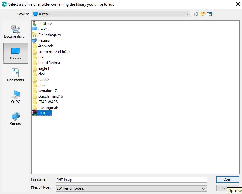
- Add the DHTLib library
- Go to Sketch> Include Library> Add .ZIP Library
- Select the DHTLib.zip file!
It has all the functions needed to get the humidity and temperature readings from the sensor.
Ther's two It’s easy to install, just download it and open the Arduino IDE.
.png)
Done!
.png)
Or! you can install the library directly from Arduino IDE:
Go to Sketch> Include Library>Manage libraries and then search for the library
.png)
.png)
Done!
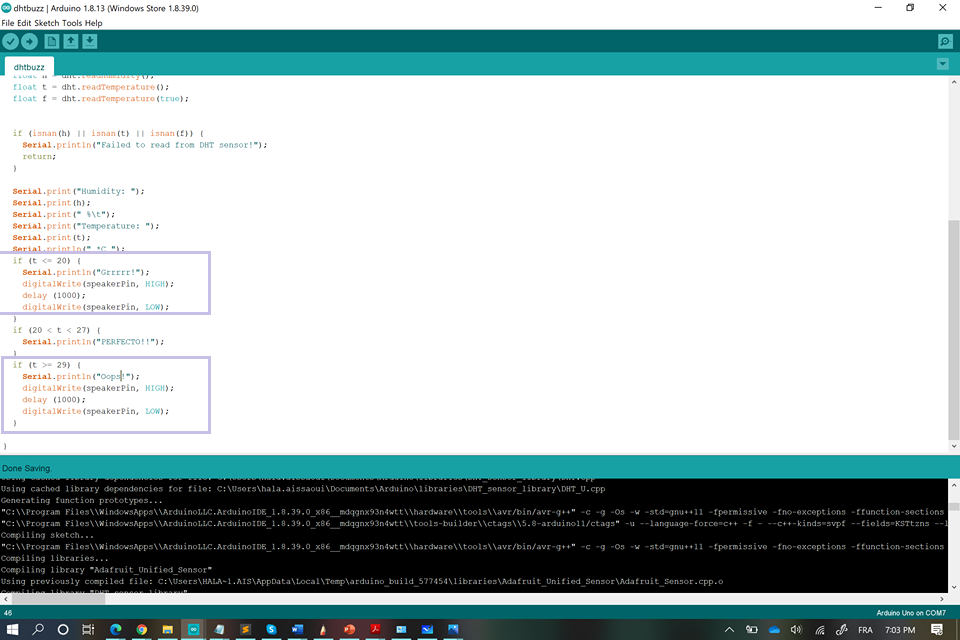
And now, it's time for the code!!
#include <Adafruit_Sensor.h>
#include <DHT.h>
int speakerPin = 8;
int length = 1;
#define DHTPIN A0
#define DHTTYPE DHT11

DHT dht(DHTPIN, DHTTYPE);
void setup() {
  Serial.begin(9600);
  Serial.println("DHT11 test!");

  dht.begin();
}

void loop() {
  pinMode(speakerPin, OUTPUT);
  delay(2000);

  float h = dht.readHumidity();
  float t = dht.readTemperature();
  float f = dht.readTemperature(true);


  if (isnan(h) || isnan(t) || isnan(f)) {
    Serial.println("Failed to read from DHT sensor!");
    return;
  }

  Serial.print("Humidity: ");
  Serial.print(h);
  Serial.print(" %\t");
  Serial.print("Temperature: ");
  Serial.print(t);
  Serial.println(" *C ");
  if (t <= 20) {
    Serial.println("Grrrrr!");
    digitalWrite(speakerPin, HIGH);
    delay (1000);
    digitalWrite(speakerPin, LOW);
  }
  if (20 < t < 27) {
    Serial.println("PERFECTO!!");
    digitalWrite(speakerPin, LOW);
  }
  if (t >= 29) {
    Serial.println("Oops!");
    digitalWrite(speakerPin, HIGH);
    delay (1000);
    digitalWrite(speakerPin, LOW);
  }

}
Download the Code!!!
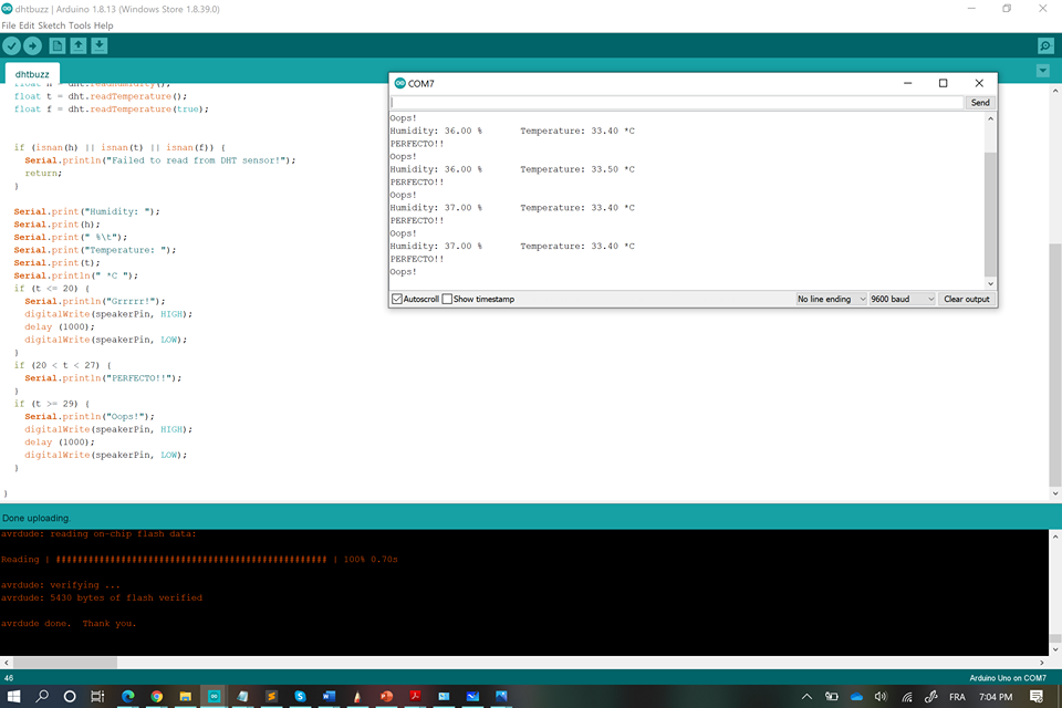
So since it's summer and surely the weather is >29°C, the buzzer starts to make a sound(with a delay of 1000ms) as an indicator for the high temperature!
In short, I hit two birds with one stone:(Buzzer+Dht11)
In addition to that you can really play with it as you want!!
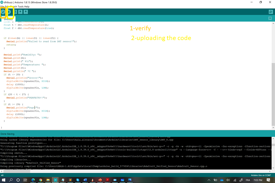
Then upload the code to the Arduino after connecting it to the PC.
.jpg)
And wait for it to work!!
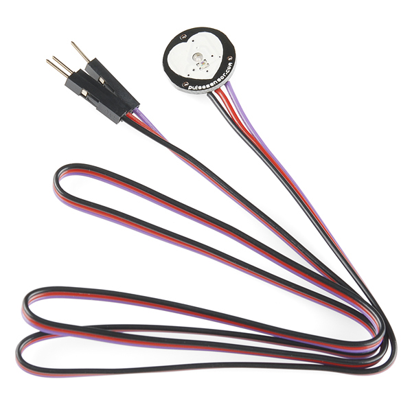
A pulse reader(Datasheet)
The Pulse Sensor is a well-designed plug-and-play heart-rate sensor for Arduino. It can be used by students, artists, athletes, makers, and game & mobile developers who want to easily incorporate live heartrate data into their projects. The sensor clips onto a fingertip or earlobe and plugs right into Arduino with some jumper cables. It also includes an open-source monitoring app that graphs your pulse in real time.
For this week, since we were told to design our PCBs from anew, it's was kind tough since we first designed and milled our PCBs for ATTINY84, but everything was in vein since those were nowhere to be found.
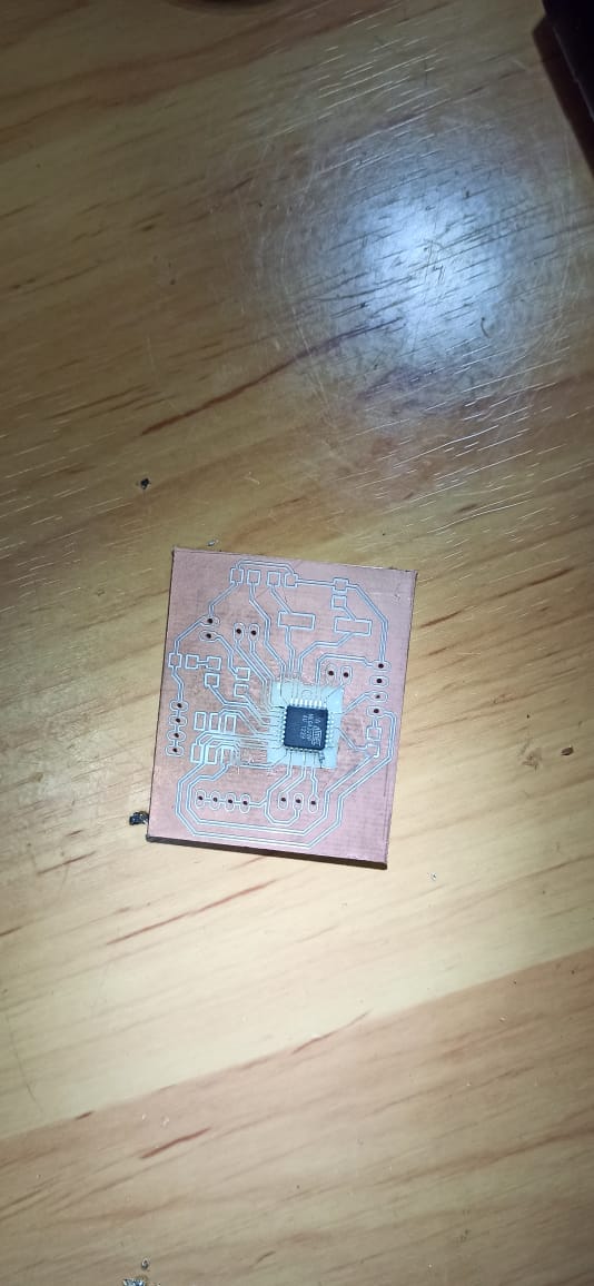
Thus we redesigned everything again for ATMEGA328p;
First, I designed a card for an INPUT of a "touch pad"
.jpeg)
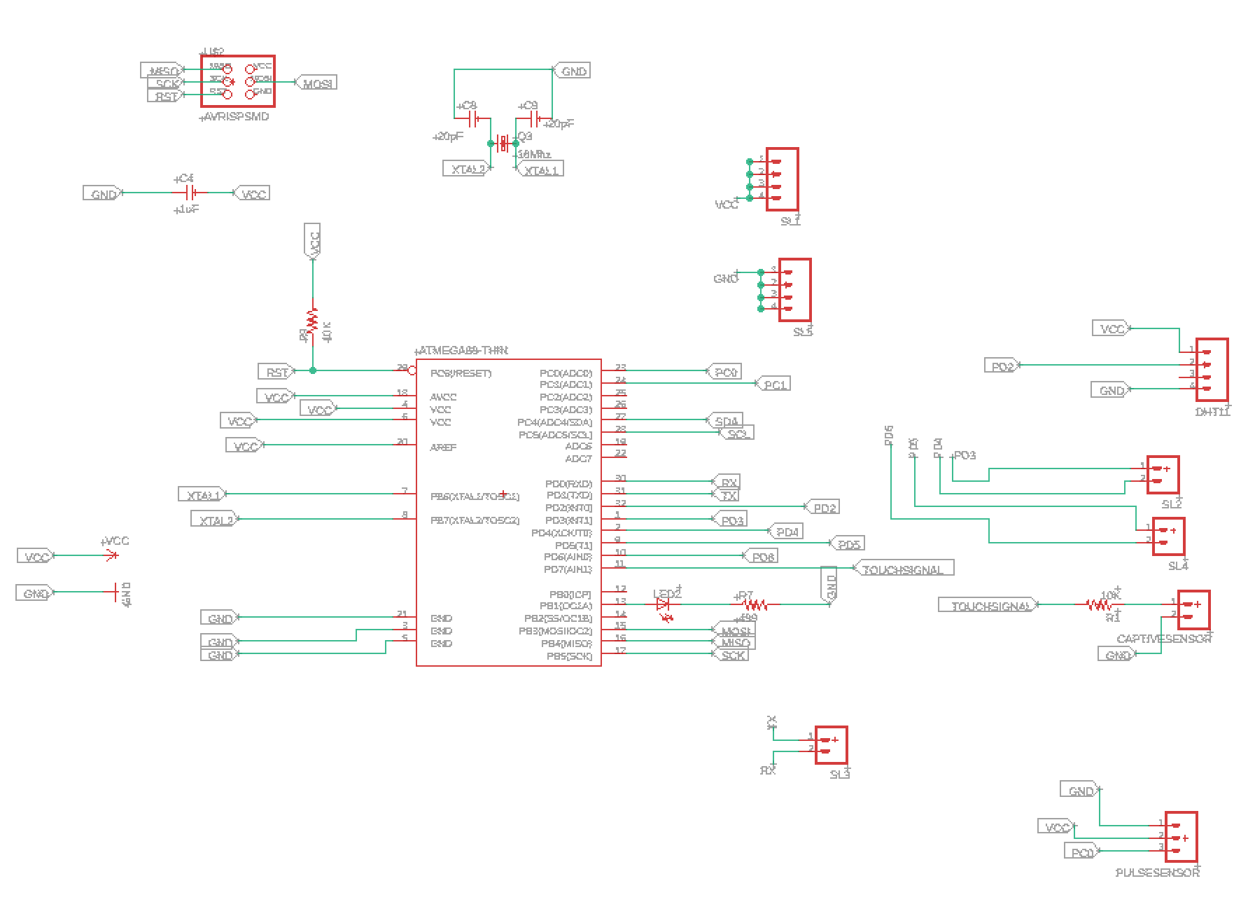
and I milled it but since as I said that the Attinys were unavailble, I decided to make a Card for different INPUTs(DHT11, Touchpad, and a pulsereader)
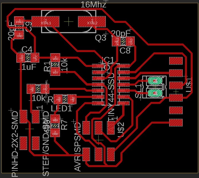
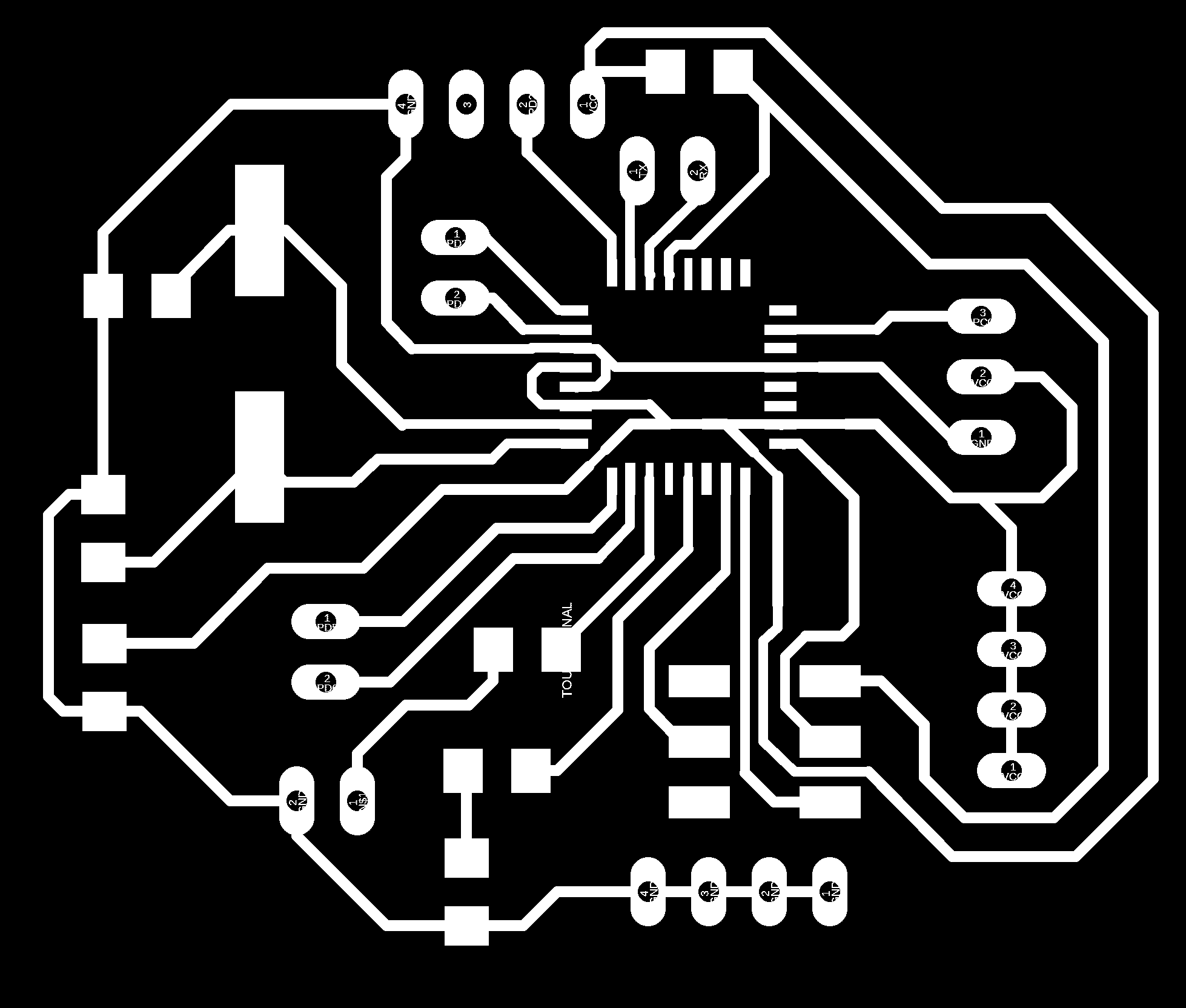
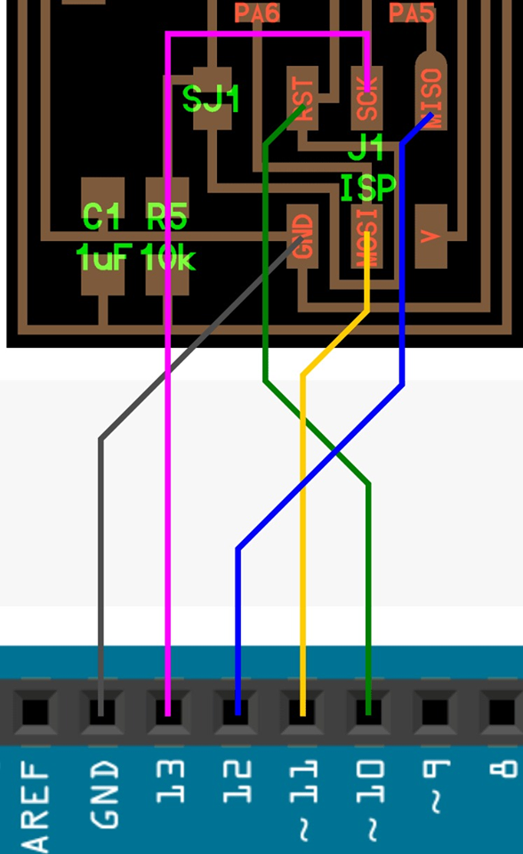
The schematic
The milling process
.jpeg)
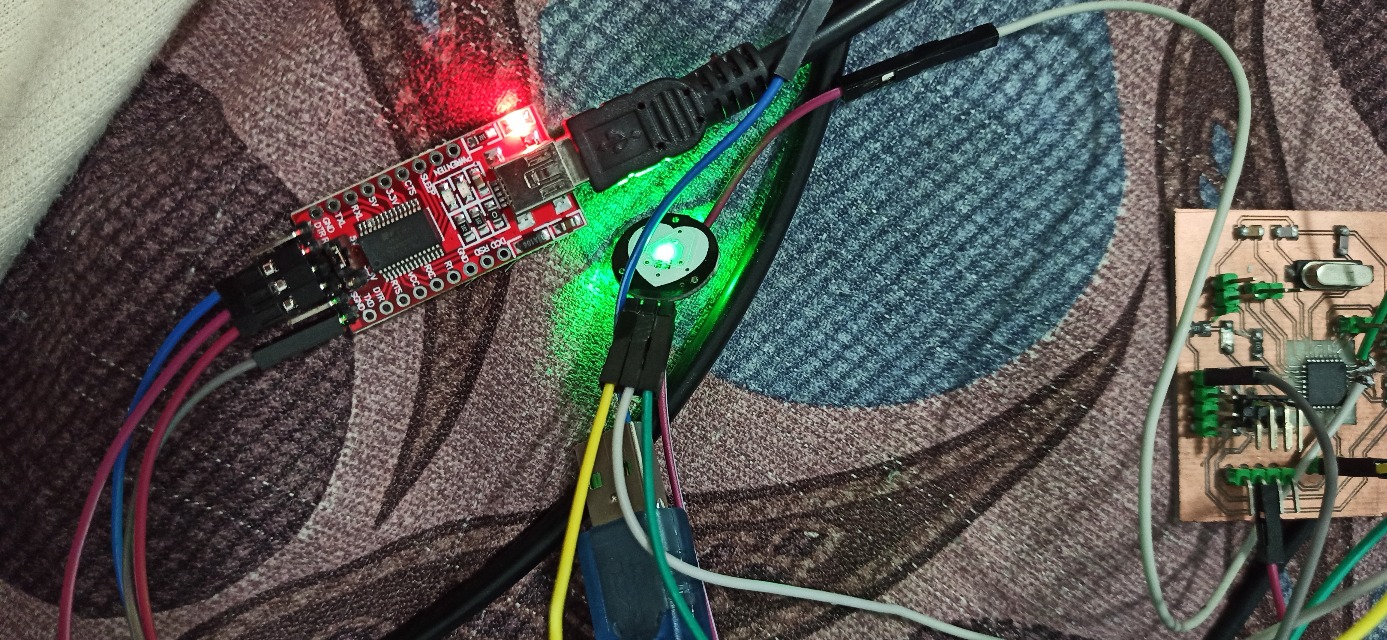
and soldering it !! since I basically copied the schematic from the my previous attiny's board I forgot that I needed something for the serial communication, which it the TX and the RX pins (these 2 pins are responsible for the serial communication of the card. They enable us to have lecture on the serial Monitor) therefore I had too choices ; either I try to solder out directly 2 wires from the microship or make the whole thing again(which wasn't that easy ) so I took the risk to do the first option and soldered directly two wires !!!
and doing the same process with the arduino
The code
#define USE_ARDUINO_INTERRUPTS true // Set-up low-level interrupts for most acurate BPM math.
#include <PulseSensorPlayground.h> // Includes the PulseSensorPlayground Library.
// Variables
const int PulseWire = A0; // PulseSensor PURPLE WIRE connected to ANALOG PIN 0
const int LED13 = 9; // The on-board Arduino LED, close to PIN 13.
int Threshold = 550; // Determine which Signal to "count as a beat" and which to ignore.
// Use the "Gettting Started Project" to fine-tune Threshold Value beyond default setting.
// Otherwise leave the default "550" value.
PulseSensorPlayground pulseSensor; // Creates an instance of the PulseSensorPlayground object called "pulseSensor"
void setup() {
Serial.begin(9600); // For Serial Monitor
// Configure the PulseSensor object, by assigning our variables to it.
pulseSensor.analogInput(PulseWire);
pulseSensor.blinkOnPulse(LED13); //auto-magically blink Arduino's LED with heartbeat.
pulseSensor.setThreshold(Threshold);
// Double-check the "pulseSensor" object was created and "began" seeing a signal.
if (pulseSensor.begin()) {
Serial.println("We created a pulseSensor Object !"); //This prints one time at Arduino power-up, or on Arduino reset.
}
}
void loop() {
int myBPM = pulseSensor.getBeatsPerMinute(); // Calls function on our pulseSensor object that returns BPM as an "int".
// "myBPM" hold this BPM value now.
if (pulseSensor.sawStartOfBeat()) { // Constantly test to see if "a beat happened".
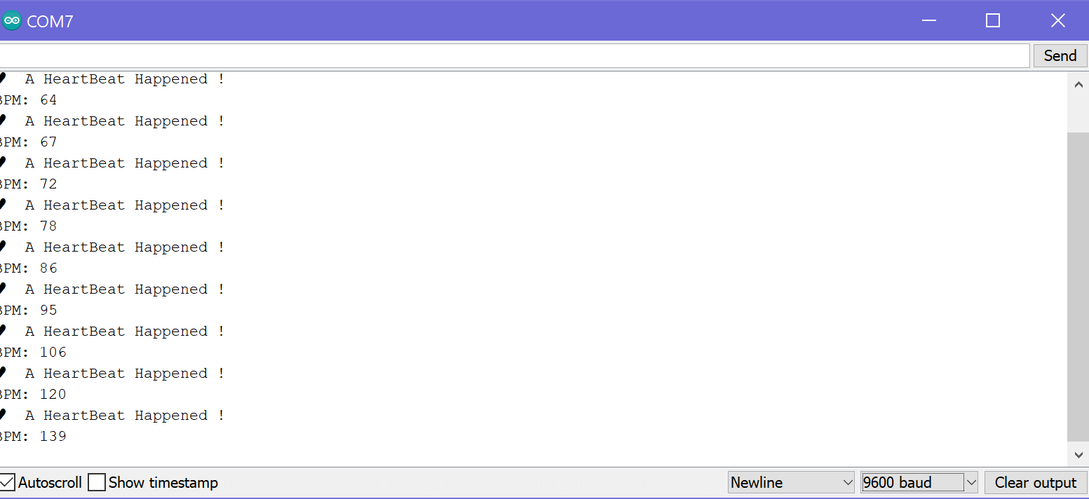
Serial.println("♥ A HeartBeat Happened ! "); // If test is "true", print a message "a heartbeat happened".
Serial.print("BPM: "); // Print phrase "BPM: "
Serial.println(myBPM); // Print the value inside of myBPM.
}
delay(20); // considered best practice in a simple sketch.
}
One thing to add, the code was written for the pulce monitor and the LED to work simultaneously as shown in the video bellow.
My Files
PULSE READER codeInput SCHEMATIC
Input BOARD