
Week 08 : Embedded programming
the assignment for this week are:
Group Assignment
- Compare the performance and development workflows for other architectures!
- Read a microcontroller datasheet
- Program your board to do something with as many different programming languages and programming environments as possible
Individual assignment
Individual assignment
Update
For this Assignment we first worked with the Arduino and the whole assignment was for the Arduino the datasheet reading, the features, etc.. and after finishing the whole Assignment, and since we already milled our Hello boards we had to redo everything.
Read a microcontroller datasheet:The Attiny24/44/84
How to read microcontroller datasheets? 5 tips for Beginners!What's more challenging was "reading" the datasheet! And I got to say, it's totally not that easy to read it.
Introduction to Attiny24/44/84
The Atmel® ATtiny24/44/84 is a low-power CMOS 8-bit microcontroller based on the AVR enhanced RISC architecture. By executing powerful instructions in a single clock cycle, the Atmel ATtiny24/44/84 achieves throughputs approaching 1MIPS per MHz allowing the system designer to optimize power consumption versus processing speed.
ATtiny24/44/84 DATASHEET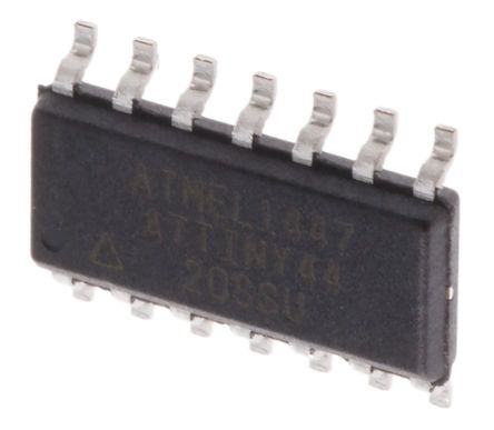
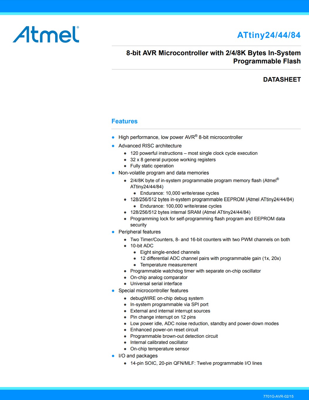
ATtiny24/44/84 Features
The Atmel ATtiny24/44/84 provides the following features:
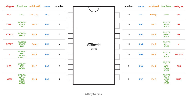
Pinout Schematic
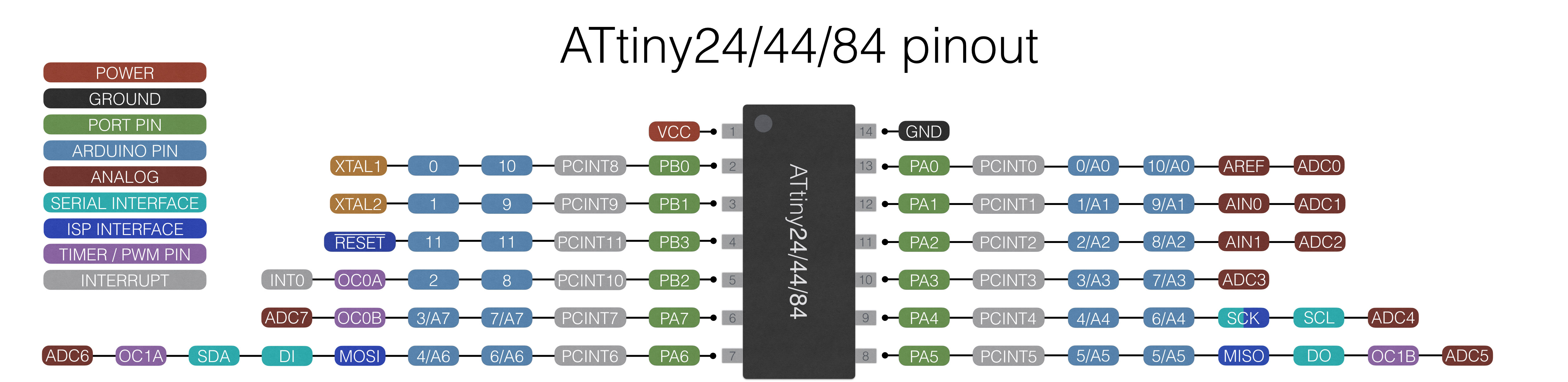
In total the Atmel ATtiny24/44/84 has a total of 14 pins.
Through pinout diagram we can understand the configurations of the pins of any electronic device!
Through DATASHEETs we get to know more about the functions associated with the pins. It has to be known in order to be used wisely.
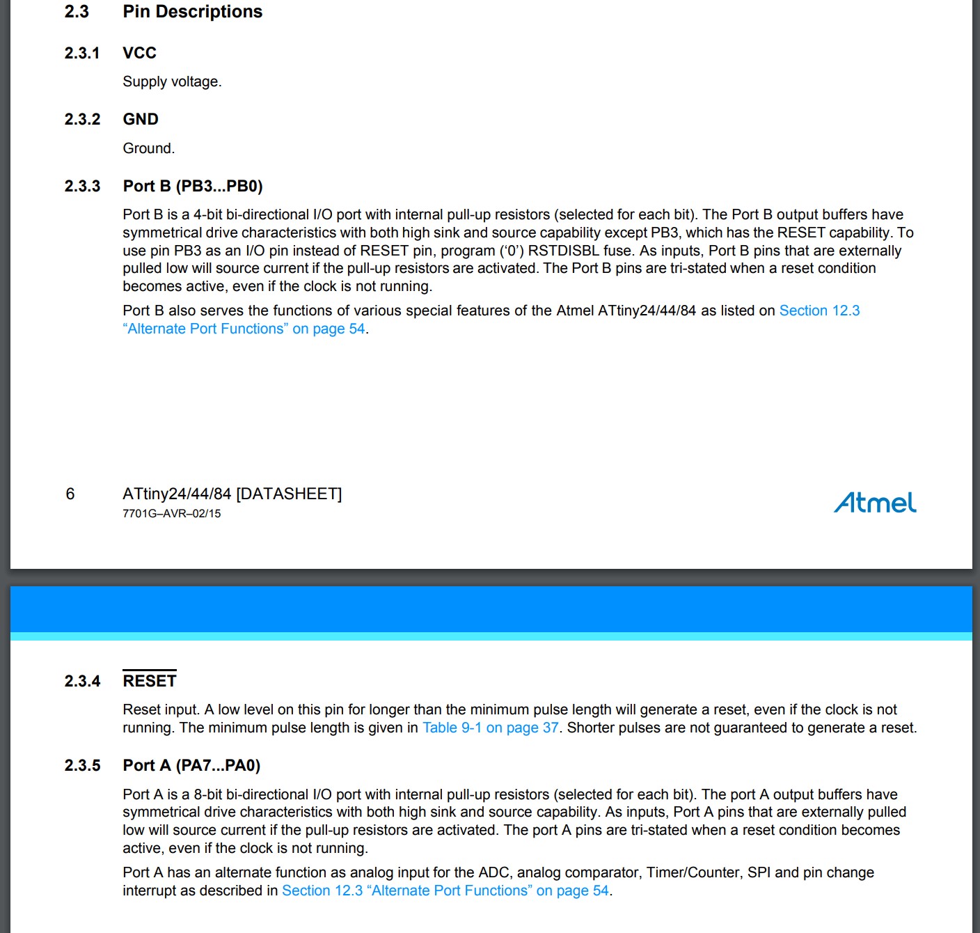
- VCC is a digital voltage supply.
- GND denotes Ground and it has a 0V.
- GND denotes Ground and it has a 0V.
- RESET
- Port B (PB3...PB0) Port B also serves the functions of various special features of the Atmel ATtiny24/44/84.
- Port A Port A has an alternate function as analog input for the ADC, analog comparator, Timer/Counter, SPI and pin change interrupt.
The Architecture
The ATTINY44 runs with the RISC Architecture. RISC or reduced instruction set computer is a computer which only uses simple commands that can be divided into several instructions which achieve low-level operation within a single CLK cycle, as its name proposes “Reduced Instruction Set”. It's performance is optimized with more focus on software. RISC mainly Used in Microcontroller.
The Block Diagram for the ATTINY44, according to the datasheet has four main sections:
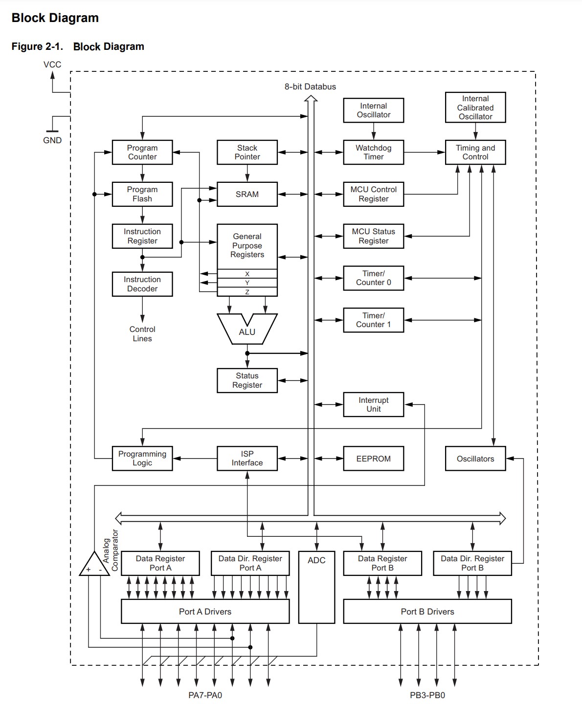
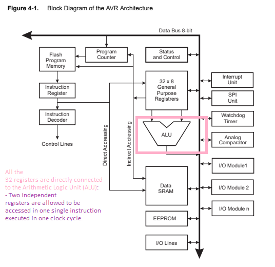
Block diagram shows the internal circuitry and the programflow
The Atmel ATtiny24/44/84 Memory
The Atmel ATtiny24/44/84 contains 2/4/8K bytes of on-chip, in-system, reprogrammable flash memory for program storage. Since all AVR instructions are 16 or 32 bits wide, the flash memory is organized as 1024/2048/4096 x 16.
Using the Arduino App to Program our boards
Arduino is a single-board microcontroller meant to make the application more accessible which are interactive objects and its surroundings. The hardware features with an open-source hardware board designed around an 8-bit Atmel AVR microcontroller or a 32-bit Atmel ARM. Current models consists a USB interface, 6 analog input pins and 14 digital I/O pins that allows the user to attach various extension boards.
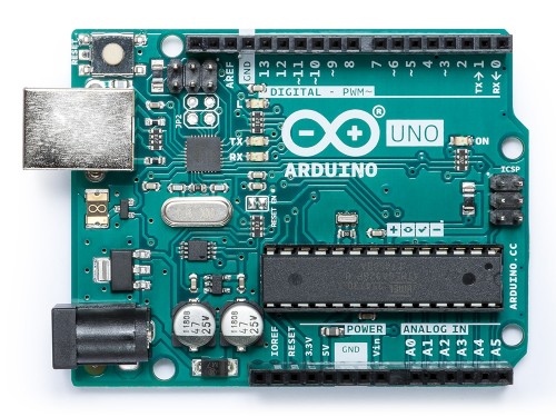
The Arduino Uno board is a microcontroller based on the ATmega328.
It's the most "standard" Arduino board currently on the market, and is probably the best choice for beginners to start with. The board is compatible with more shields (add-onboards) than other models.
Its main limitation is the ATmega328 chip, which doesn't have a lot of SRAM or flash memory. That limits the kinds of programs you can load on chip-if your project involves a display or otherwhise needs to store and use any form of images or audio data, 2KB of memory probably isn't going to be enough.
Getting started
You can download the Arduino software and get started with it.
Since I'm new to this, I just followed online instructions
- Here's some instructions on what to do after downloading the Arduino software!
- Then comes the ‘print’ option and ‘preferences’. When you will click on ‘Preference’ option:
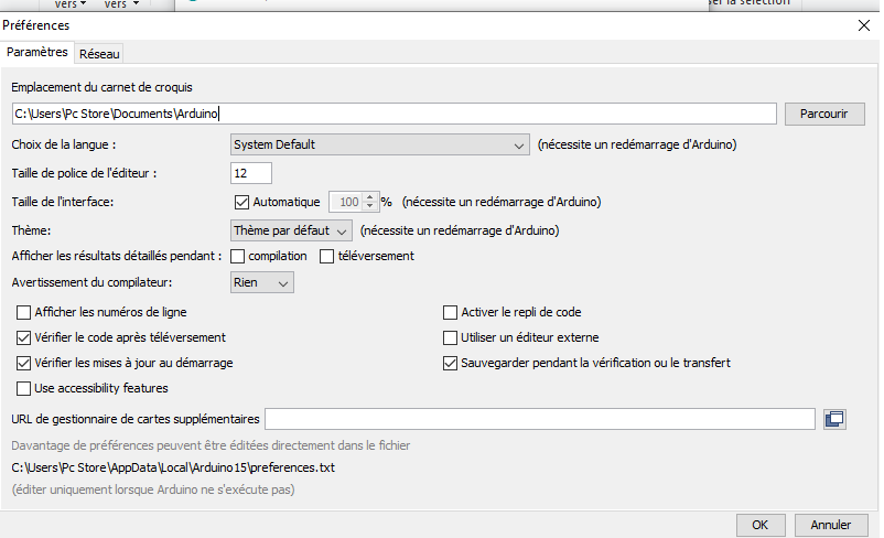
This window will open and it will be showing sketckbook location, the language used here, the size of witing, etc..
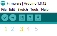
- The icon numbered a ‘1’ is of ‘verify’.
- The icon numbered as ‘2’ is to upload the sketch into your micro controller.
- The icon numbered as ‘3’ is of ‘New’.
- The icon numbered as ‘4’ is of ‘open’.
- The icon numbered as ‘5’ is of ‘save’.
Arduino CODE 1 Using Arduino as a programmer
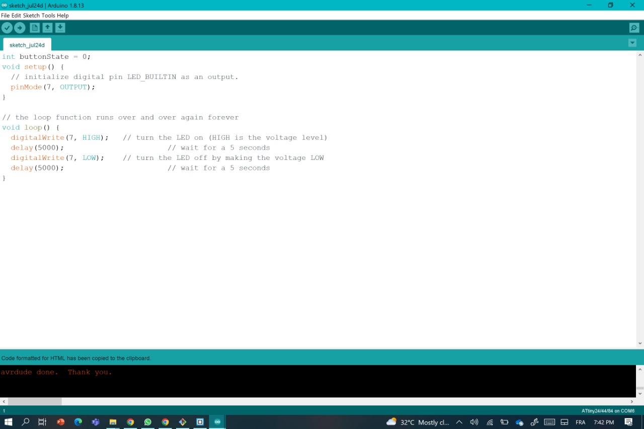
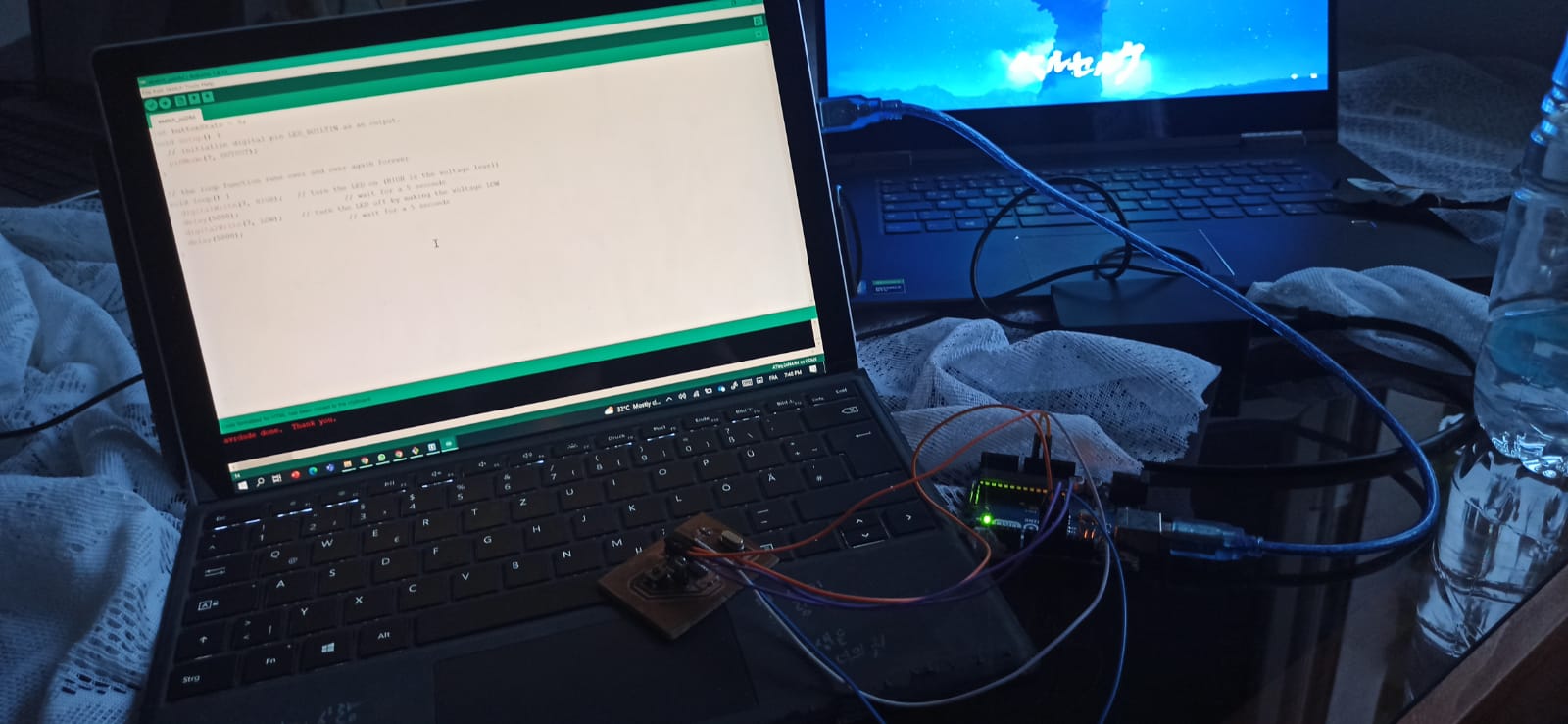
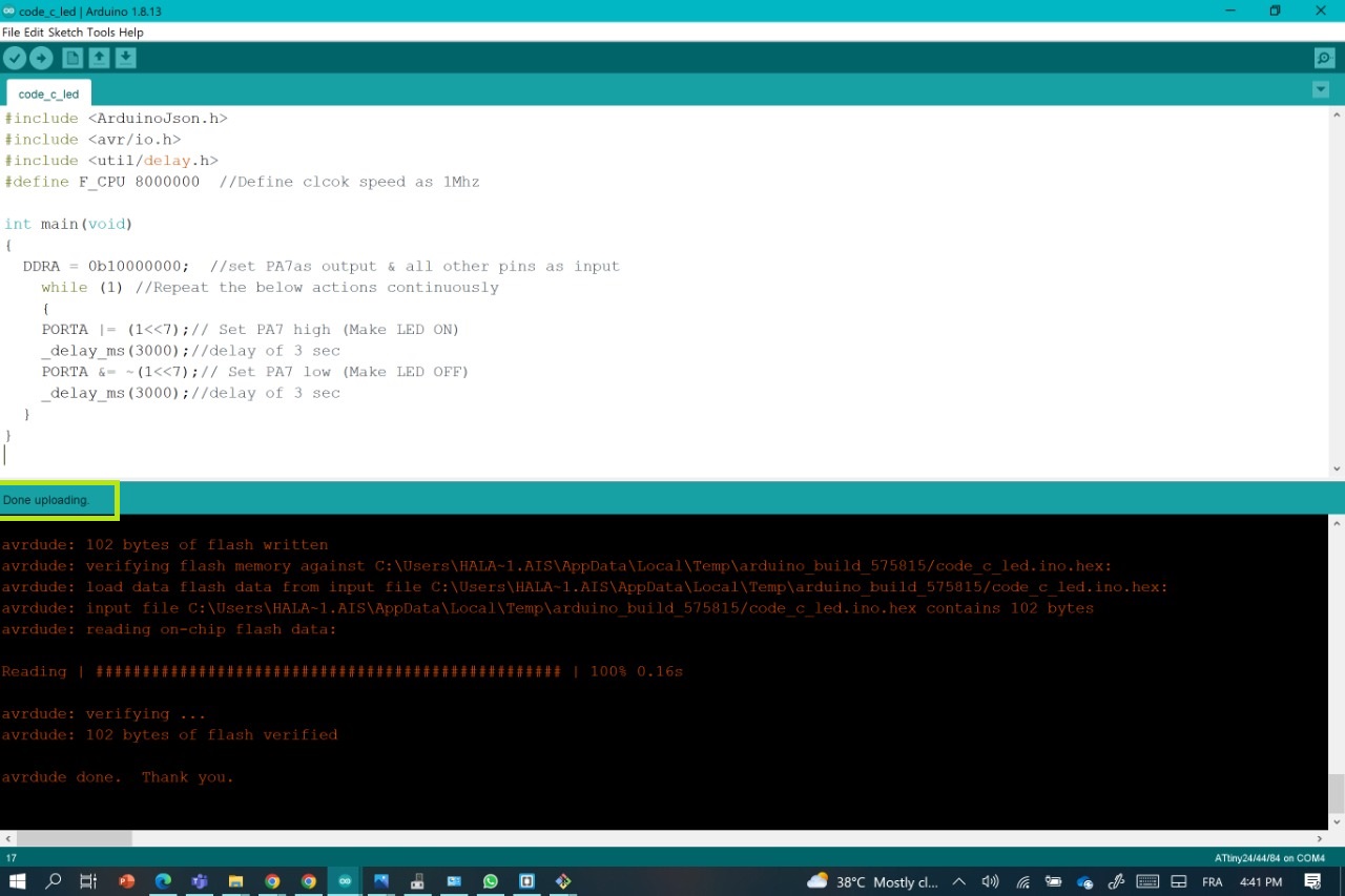
After downloading the software now it's time for uploading the code by clicking on the icon '2'.
For the wiring I did the same thing as in the 6th week except for that, the arduino code is so simple, it's to make the LED of the board to blink every 5 seconds.
int buttonState = 0;
void setup() {
  // initialize digital pin LED_BUILTIN as an output.
  pinMode(7, OUTPUT);
}

// the loop function runs over and over again forever
void loop() {
  digitalWrite(7, HIGH);   // turn the LED on (HIGH is the voltage level)
  delay(5000);                       // wait for a 5 seconds
  digitalWrite(7, LOW);    // turn the LED off by making the voltage LOW
  delay(5000);                       // wait for a 5 seconds
}
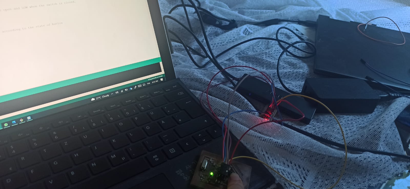
And this is how it turned out
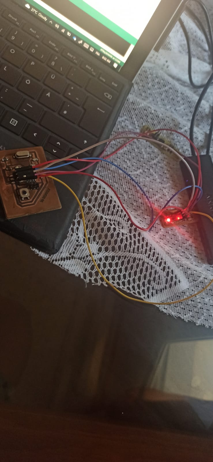
I tried another code to control the blinking of the led with the pushbutton
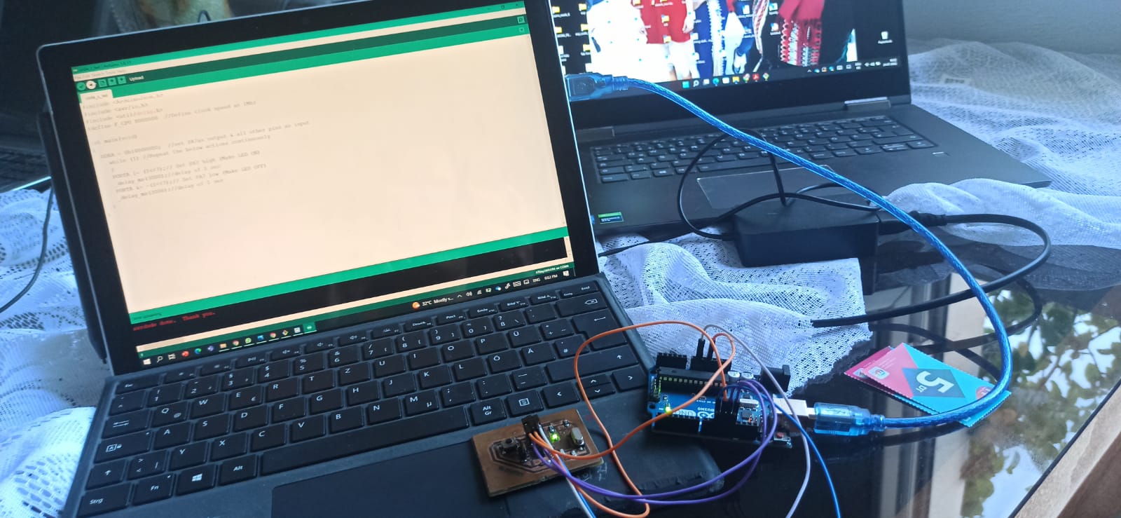
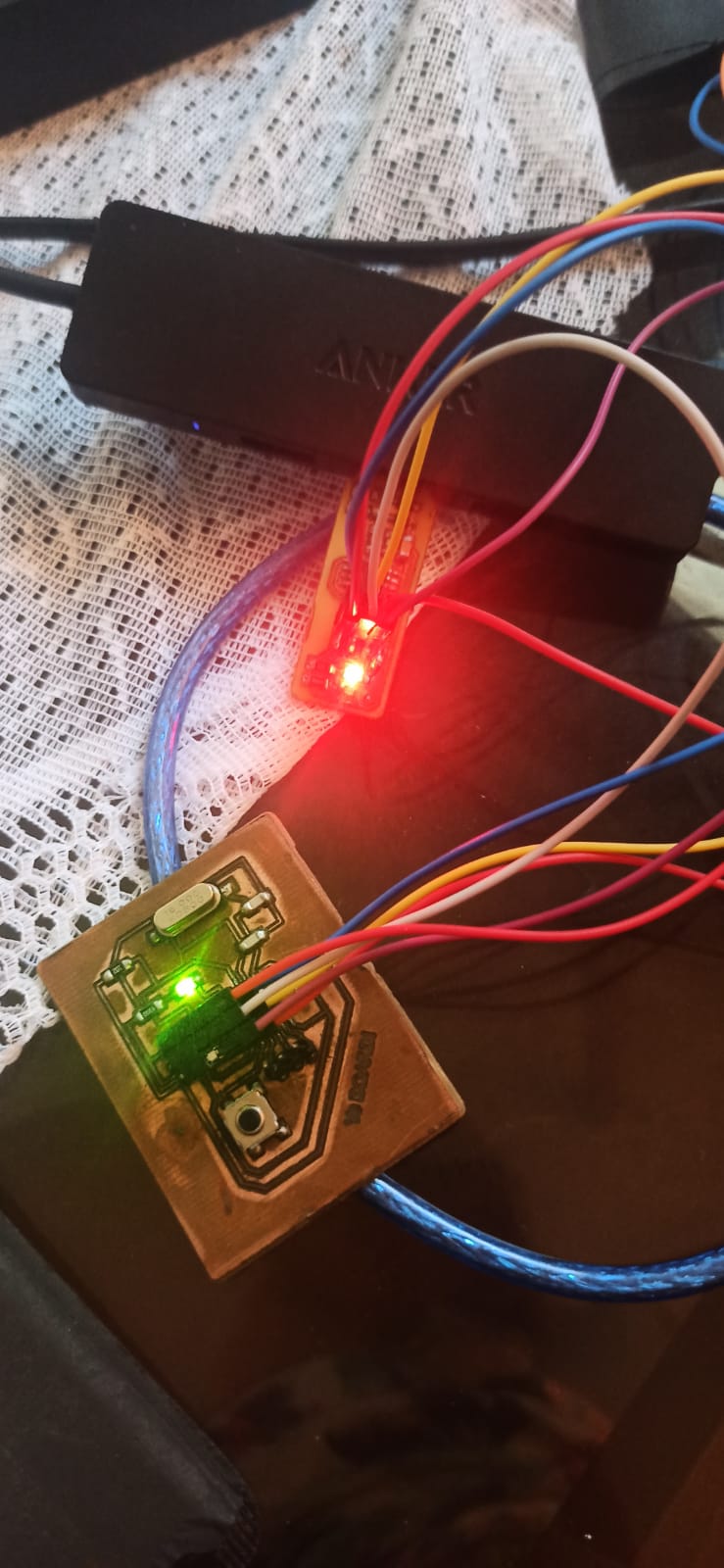
For this part, I used another programmer from a previous WEEK: my FabISP
and all what I needed to do now is connceting it with my Hello Board
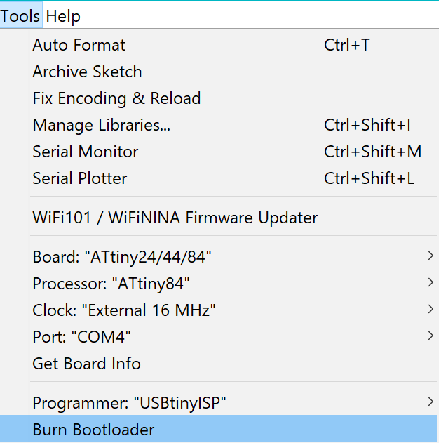
And now all what we need to do is making some changes in the Arduino software before loading the code into the board
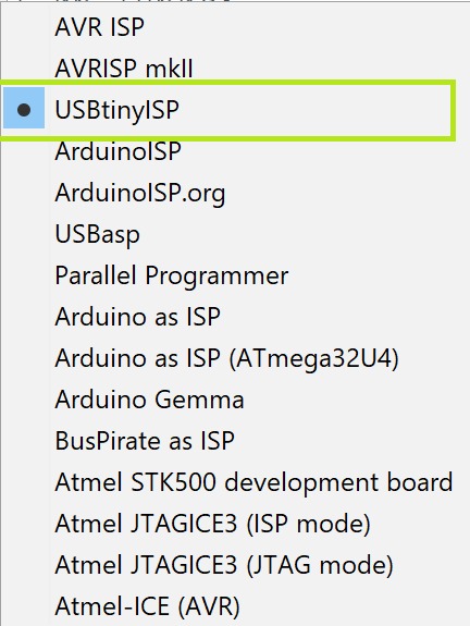
FIRST thing first: CHANGE THE PROGRAMMER
I did everwthing, but I had a problem with detecting the port of the ISP first of all,
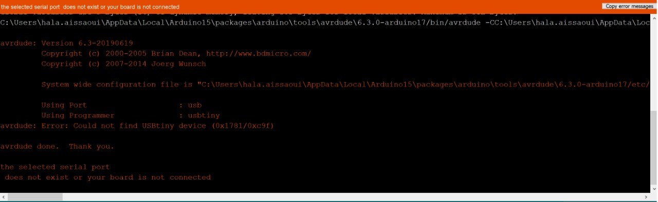
despite the fact that we already downloaded its Driver since the days of the days of the 4th week it seems that I needed to download the driver from the very beginning
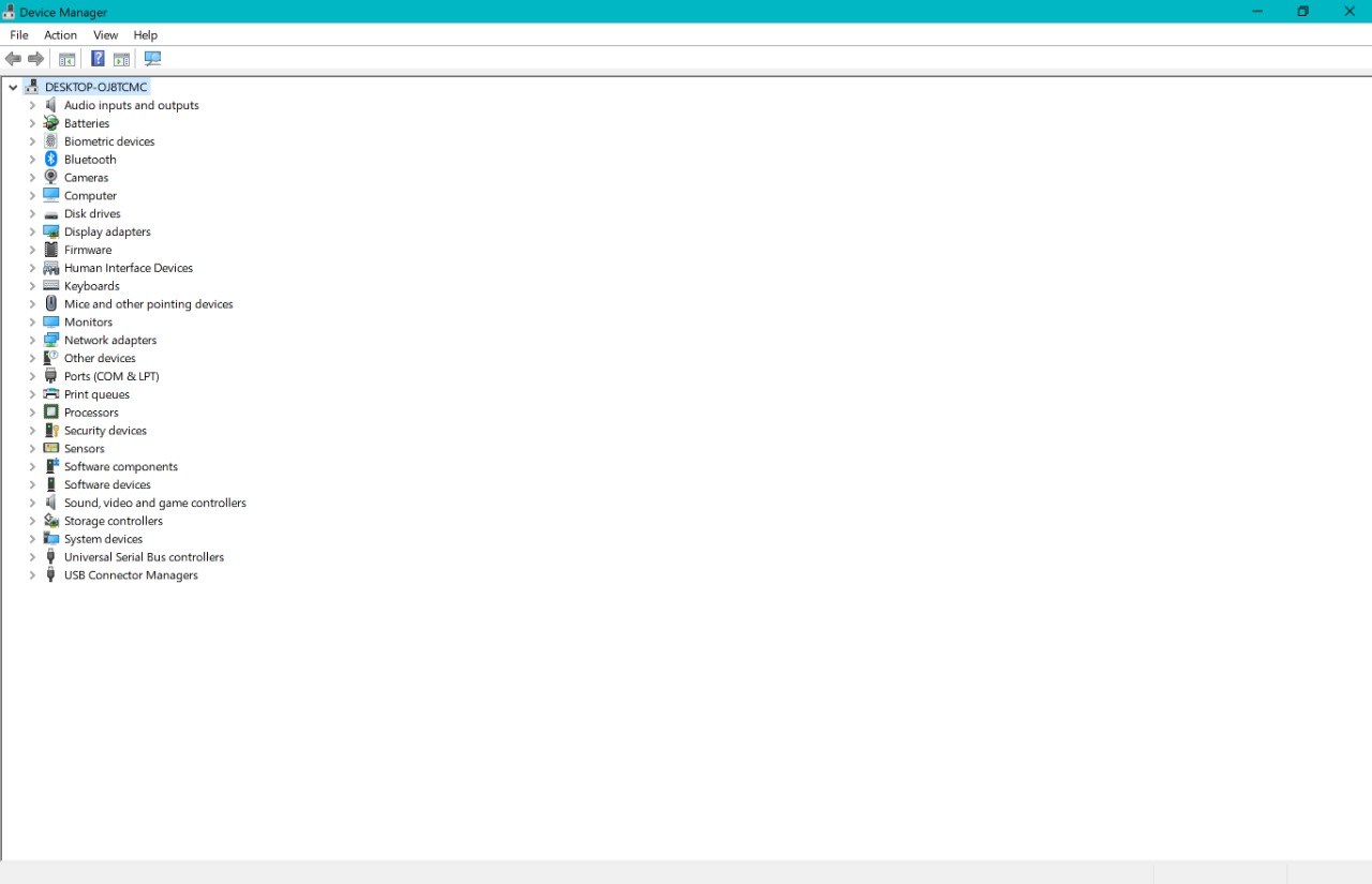
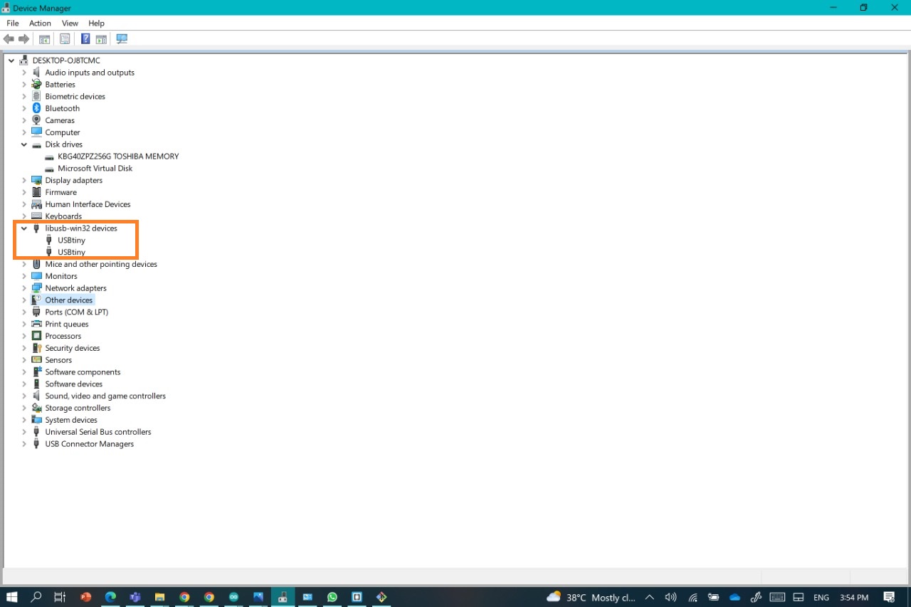
therefore I'm not going into so much details for this one, except for the part where my Laptop recognized the ISP
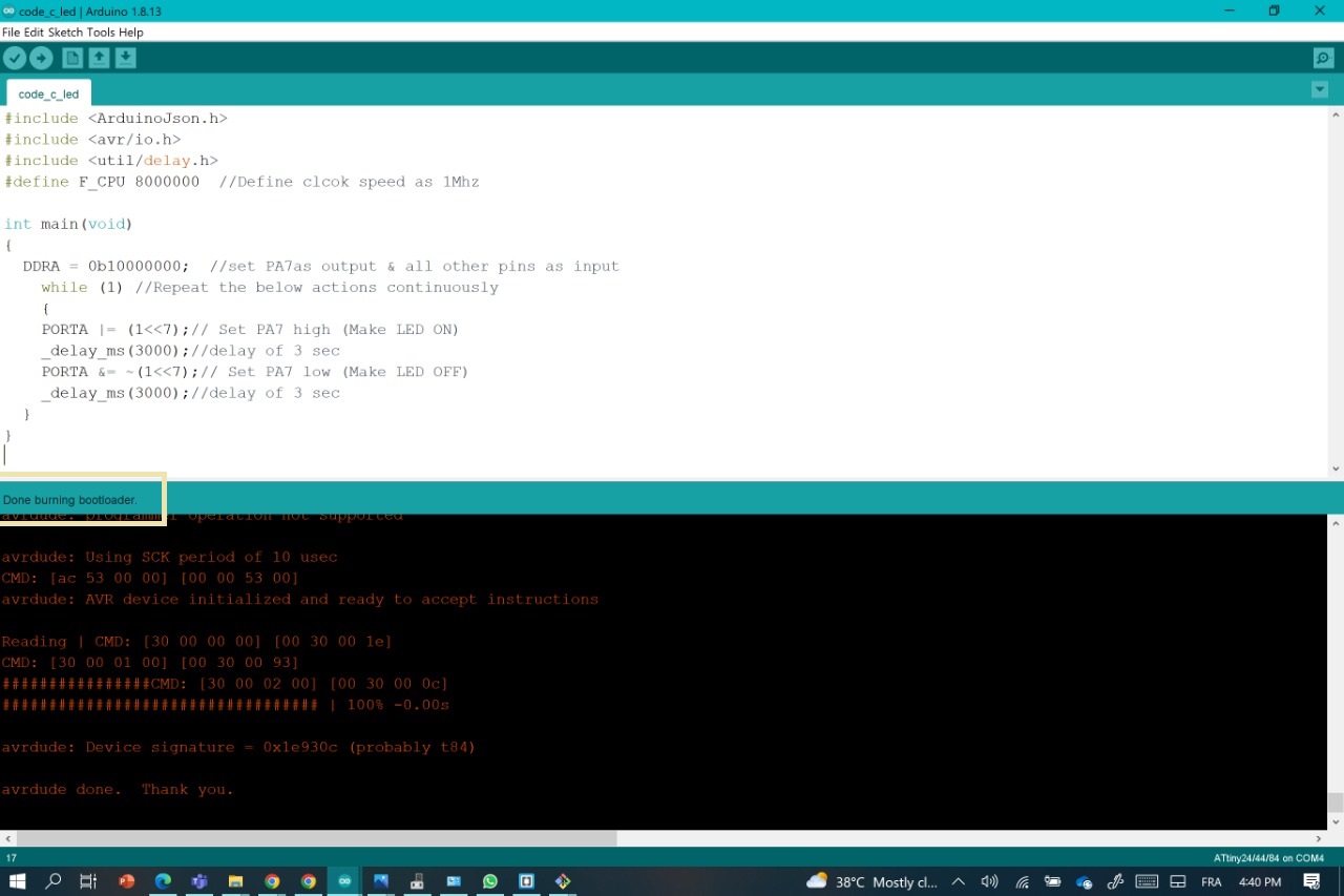
so once again, we do the same steps and mostly changing the Programer part ist the most important par, then Burn the Boatloader before uploading the code into the board through the FabISP
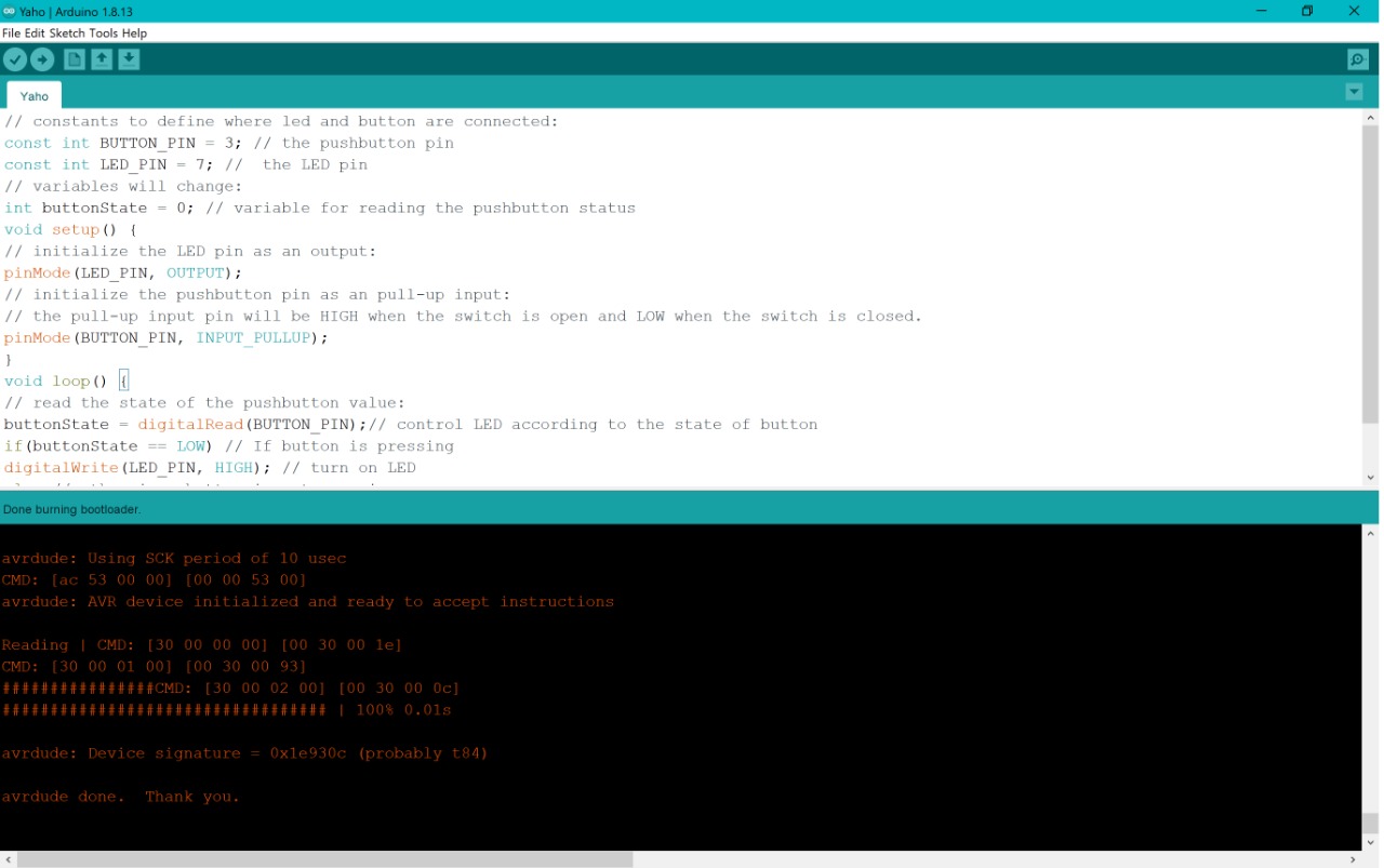
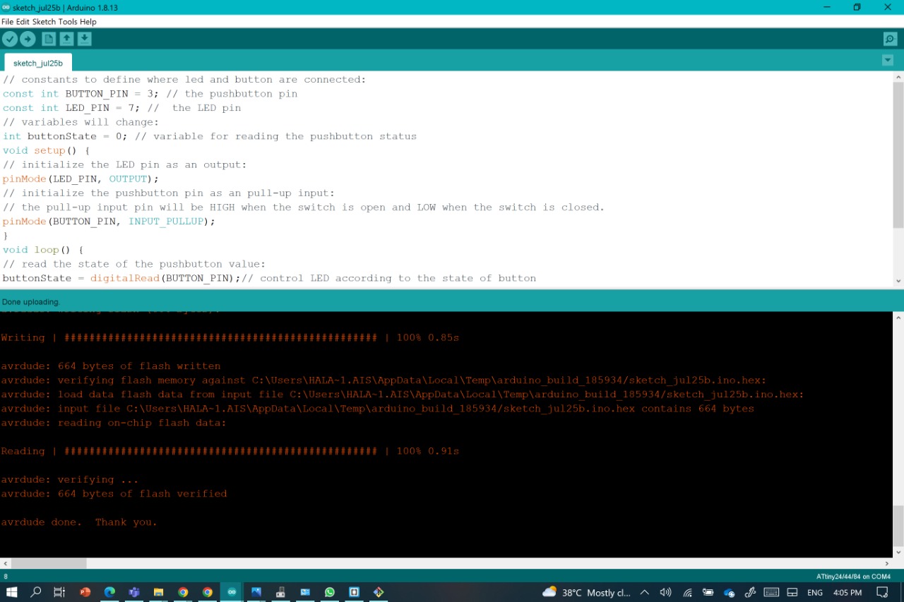
THE CODE
// constants to define where led and button are connected:
const int BUTTON_PIN = 3; // the pushbutton pin
const int LED_PIN = 7; //  the LED pin
// variables will change:
int buttonState = 0; // variable for reading the pushbutton status
void setup() {
// initialize the LED pin as an output:
pinMode(LED_PIN, OUTPUT);
// initialize the pushbutton pin as an pull-up input:
// the pull-up input pin will be HIGH when the switch is open and LOW when the switch is closed.
pinMode(BUTTON_PIN, INPUT_PULLUP);
}
void loop() {
// read the state of the pushbutton value:
buttonState = digitalRead(BUTTON_PIN);// control LED according to the state of button
if(buttonState == LOW) // If button is pressing
digitalWrite(LED_PIN, HIGH); // turn on LED
else // otherwise, button is not pressing
digitalWrite(LED_PIN, LOW); // turn off LED
}
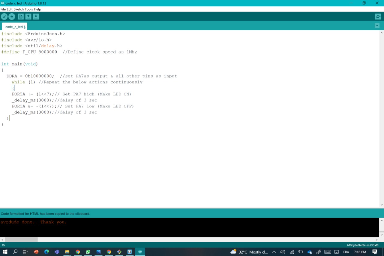
Code C
To have a quick understanding of the port manipulation in the C code check this
LED is connected to PA7 & push button to PA3.
So, as a first step we have to define PA7 as digital output pin.
For this we use DDR command.
In general DDR command are:
DDRA =0xFF or DDRA =0b11111111DDRA =0x00 or DDRA =0b00000000
"0" represents input.
PORTA |= (1<<7) or PORTA |= (0b10000000) &= ~(1<<7) or PORTA &= ~(0b10000000)Note: (1<<3) means 1(i.e 0b00000001) will be rotated three times towards left.
For more Infos, check this one
For this code it's the direct translation of the Arduino code, so in short is going to make the LED blinks every 3 seconds!
#include <ArduinoJson.h>
#include <avr/io.h>
#include <util/delay.h>
#define F_CPU 8000000  //Define clcok speed as 1Mhz

int main(void)
{
  DDRA = 0b10000000;  //set PA7as output & all other pins as input
    while (1) //Repeat the below actions continuously
    {
    PORTA |= (1<<7);// Set PA7 high (Make LED ON)
    _delay_ms(3000);//delay of 3 sec
    PORTA &= ~(1<<7);// Set PA7 low (Make LED OFF)
    _delay_ms(3000);//delay of 3 sec
  }
}
Using ARDUINO UNO as a Programmer
Using FabISP as a Programmer
Group Assignment
For this part of , here's the direct linkfor the assignment
For this Assignment we've been told to campare the performance and developement workflows for other architectures
Files
CODE LINK
PUSH BUTTON LINK
CODE C LINK