
Week 04 : Electronics production
the assignment for this week are:
The group assignment
- Characterise the design rules for our PCB production process!!!
The individual assignment
- Make an in-circuit programmer by milling and stuffing the PCB!
- Test it !
The group assignment
Testing the Milling traces
A for this part of the Assignment, we had to test the capability of our milling maching using the milling traces test file from the fab academy archive.

PS: You can check the whole thing from the directlink of the groupe assignment!
The individual assignment
What can I say about this Assignment?
Do I have to talk about the real struggle (plus the Corona)???
Na !! LAISSE TOMBER
I JUST can't believe that we really made it through after this ALIVE!!!! I costed us like seriously BLOOD, SWEAT AND TEARS !!!!
Nahh!!! it wasn't really that bad, though we did really spend a lot of time and a lot of broken tools to make it !!!
Anyway,
Let's get strated:
Making the Fab ISP
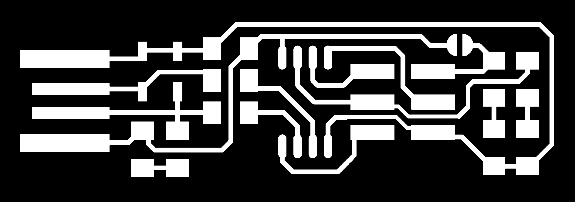
- Exporting the Fab-ISP:
- Setting the pararmeters:
- The milling:
- Soldering:
- Programming:
make flash =>With this the command is able to be uploaded to the ISP
make fuses => the special sittings of the Microcontroller
make rstdisblthe last command which is the command to disable the pins and the ISP to be programmed again!- Connect both of the new(2) and the programmed ISP(1) to each other onnect the old one to the PC using the USB hub
- Unzip the same folder that we downloaded again, The only difference is that you have to change its name to whatever you want!
- Open the mark file with NOTEPAD Here you have to only change the
- Open GIT Bash and execude the following commands
Since we already had been told to choose from the various versions of Fab-ISP to make, but we decided to work with Brian's ISP.

For this of the work, we had to upload the .png file to the Fabmodules, which is the easiest way to generate the G-codes to be milled afterward!!
.png)
.png)
.png)
.png)
.png)
And now we need to fix the parameters, then calculating the tool path and finally downloading the G-codes file for the CNC to do it's works .
We have to do the same thing for both of the outlines and the traces with some slight differences!!
.png)
.png)
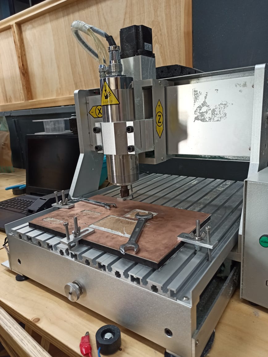
For this part of the work , I had to say that we spend ages fixing the right positions, the position of the copper plates , and the tool..
The tool is definetly the most important part of everything..
We had a lot of tools that got ruined
.jpeg)
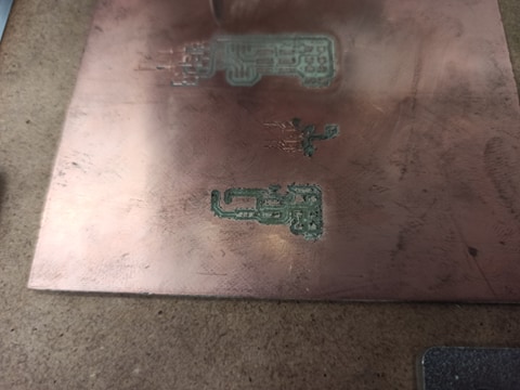
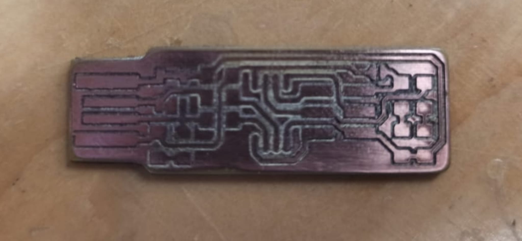
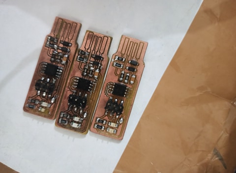
After a lot of broken tools, alot of ruined copper plates and many hours of working,
.jpeg)
We finally succeed at making a decent board for the first time!
.jpeg)
For this part, we had to be carefull with our components, and since it's the first time
.jpg)
.jpeg)
For a proper soldering experience, have your components in order and then begin with the soldering part!!
.jpeg)
Et voilà!!
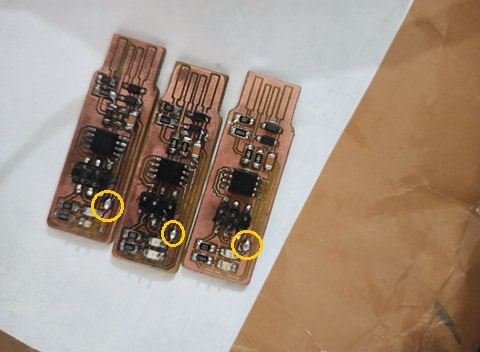
PS:These jumpers we have them unsodldered before starting the programming, 'cause two of the ISPs didn't show any sign of working untel we done that!
However it's your choice to solder or unsolder it and it depends on your ISP and how you want supply your VCC , so in other words, it's not an obligatory thing to do!
For this part, I needed to download the following softwares and files to work with;
GIT
WinAVR
Zadig, which is the driver that we're going to work with!!
And this zipped file!
Programming the ISP using ARDUINO
As a first step we had to programm the first ISP using the Arduino and then use it to programm the others.
First of all we need to do the following
Arduino>Examples>ArduinoISP>
.png)
And then uploading it in the Arduino to make it capable of programming the ISP!!
.png)
And then disconnecting it for now!
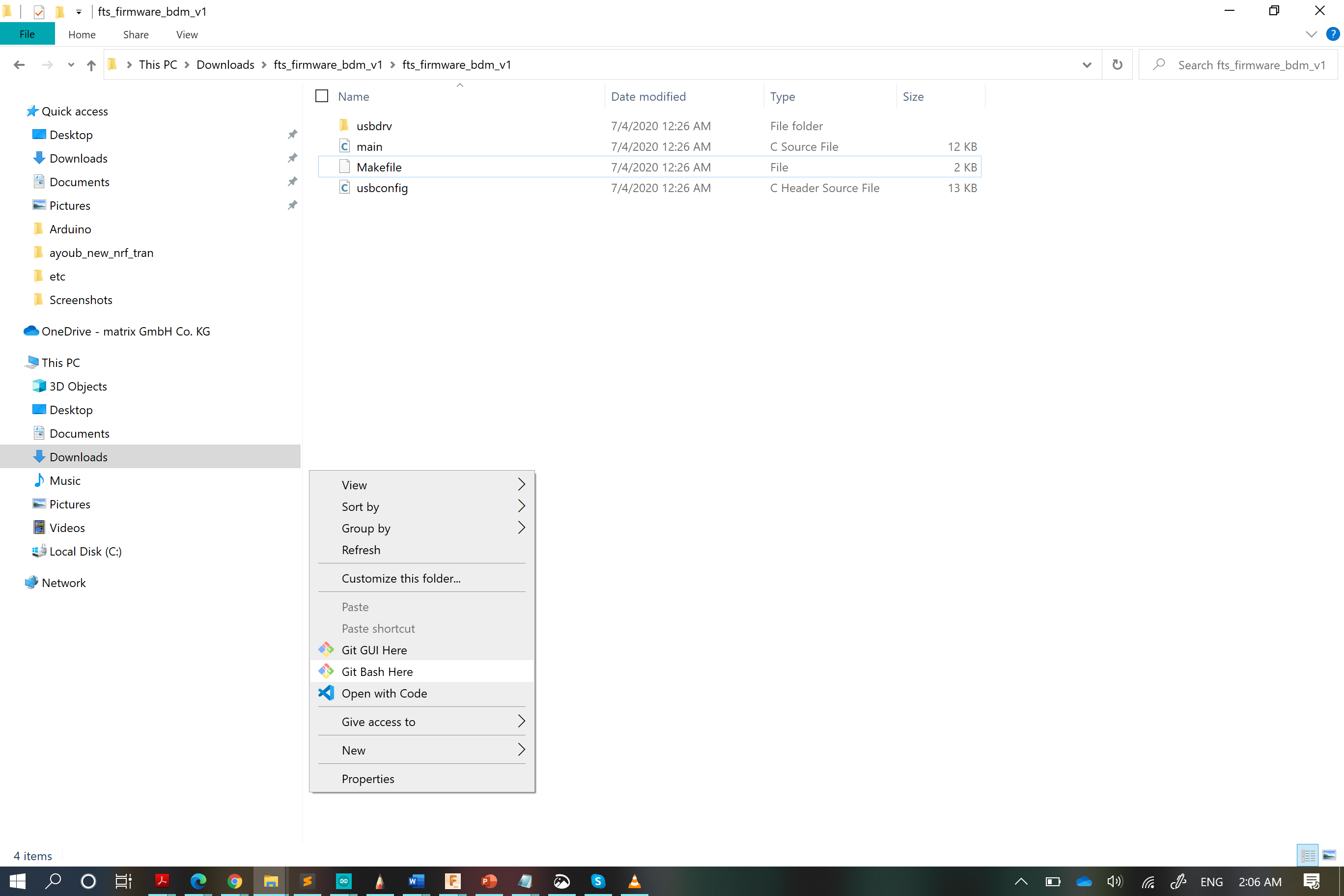
Remember the zipped file that we downloaded it?! we unzipped it , open it and then
.png)
.png)
.png)
Inside this Makefile there's these commands or instructions on what to do to programm the FabISP and it is more like a programming file that was made to work with the fabISP.
The commands are to be excuted from the GIT Bash!
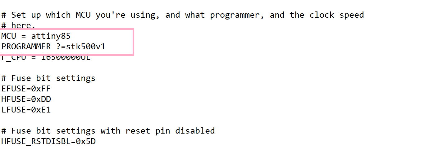
But since we're going to work with the Arduino for now , we had to modify some lines before !!
Since we're using the Attiny85 as then microcontroller of the ISP and the Arduino as the programmer, we had to change the commandlines for thetask to be completed
.png)
Then changing the ports!
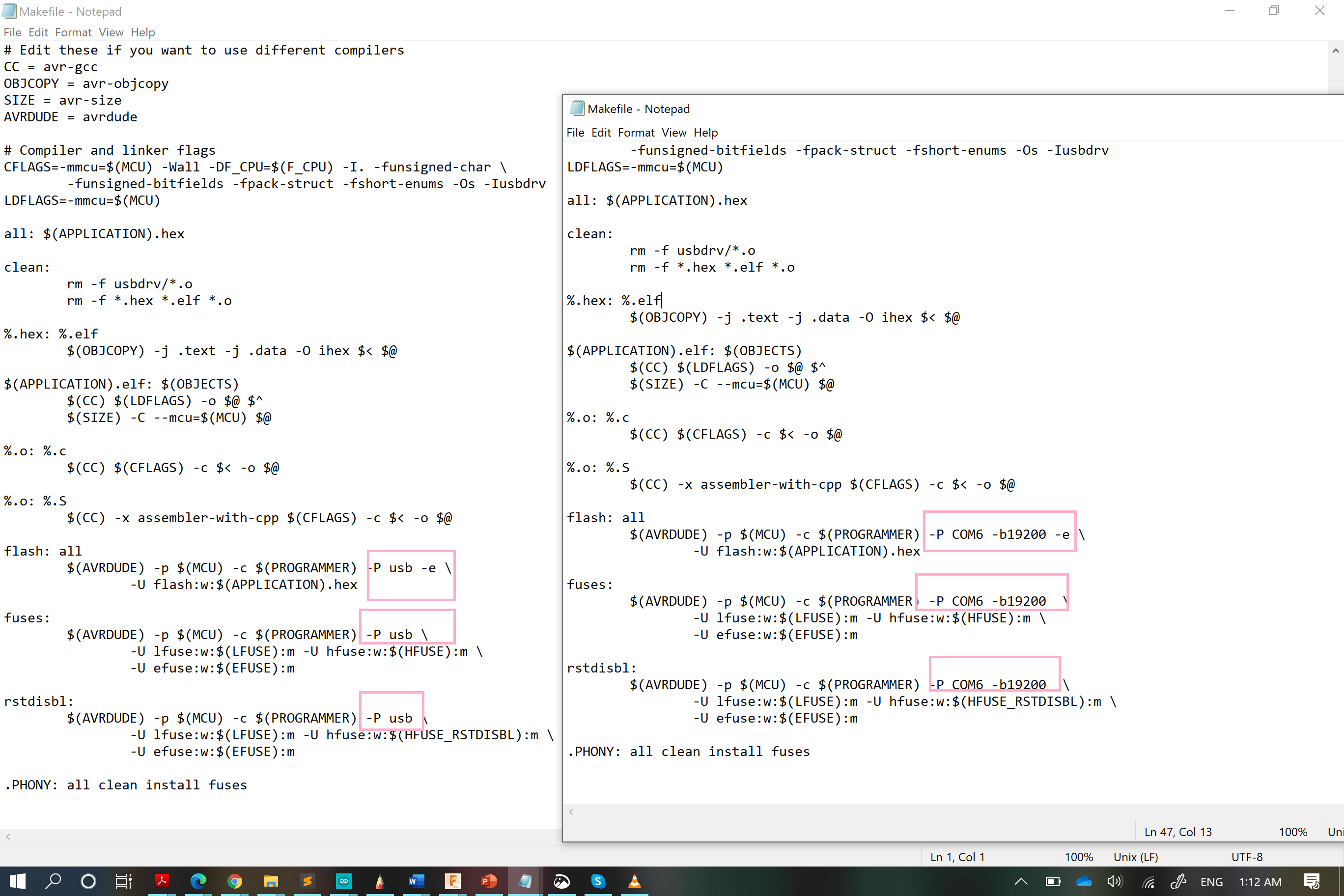
DONE
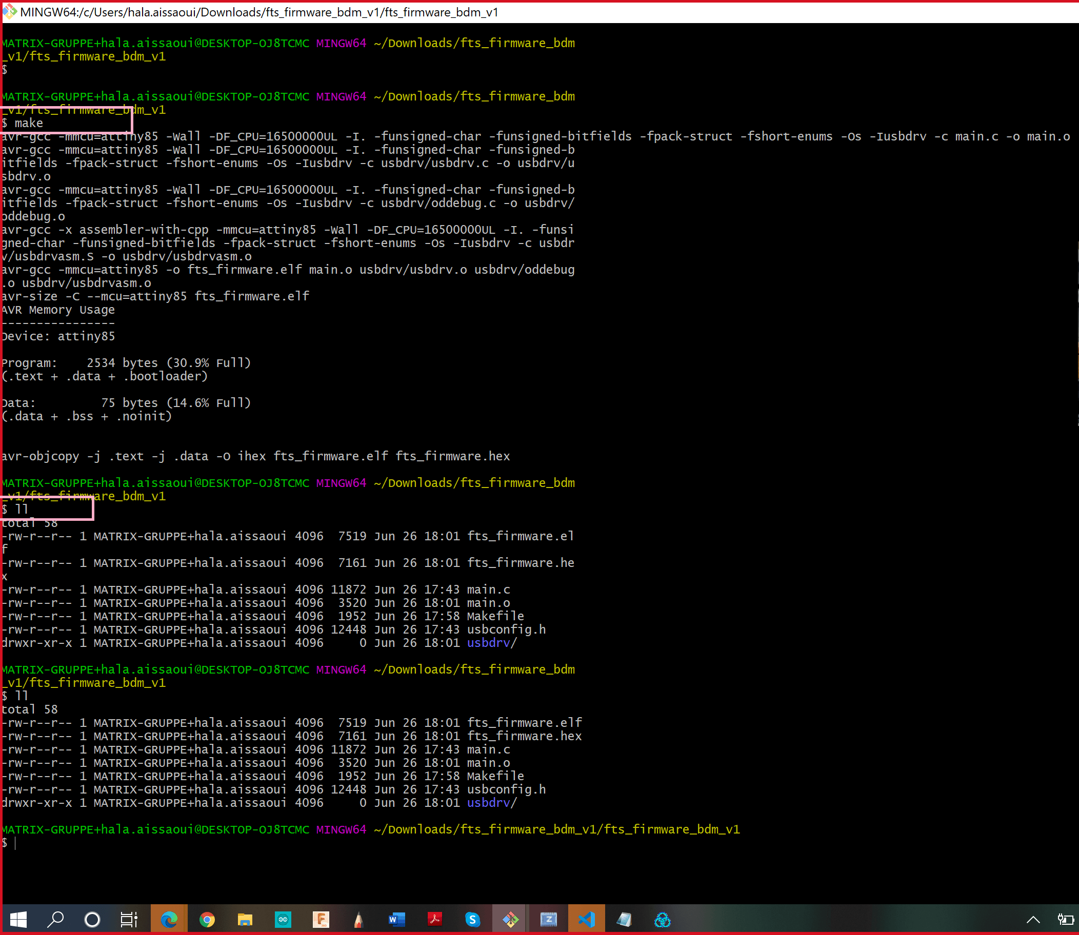
Now open the Git Bash in the unzipped file(I decided to called this way since its name is so long xD)!
Anyway, Type the commands:
ll to check your current position!
make to check if everything is fine !!
Then Connect the FabISP to the Arduino; we need to have it connected like this!!
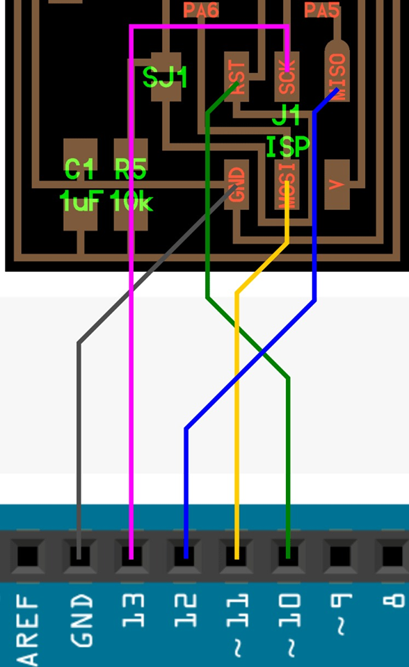
.jpg)
And then have the ISP connected to the PC
Now we have to open the Git Bash to run the commands bellow to the ISP!!
Disconnect the Arduino from the PC! and tada programming the ISP is finished
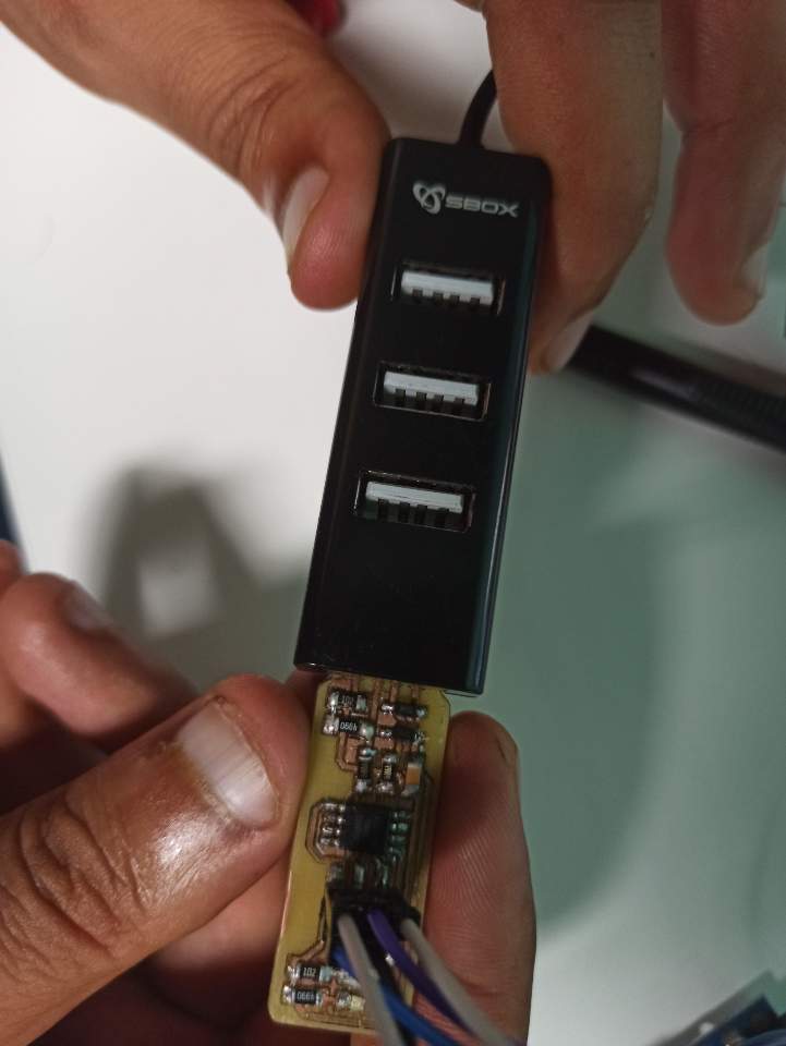
Connect the ISP to an USB hub and connect it to the PC. then open the Zadig
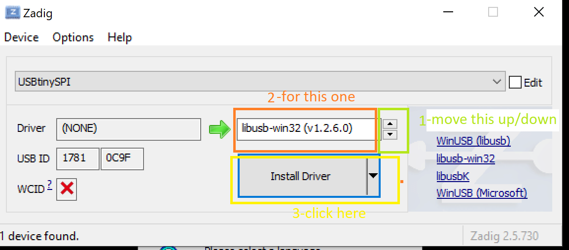
And now it's time to check if the driver is installed and the ISP is recognized by the computer
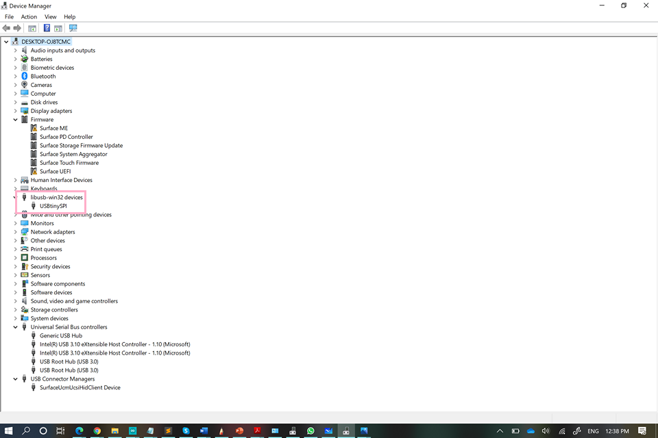
The Fab-ISP started to work!!
.jpg)
Programming the ISP using another ISP
Well, for this part there's not that much difference to using the Arduino, it's basically the same steps ;
MCU = attiny45 to MCU = attiny85
make flashmake fusesmake rstdisbl
And yeah , you're done ^^
PS: check if the ISP is recognized by the Computer, after connecting it alone to it!
And yaaaay~~ MINE works
.jpg)